4. Computer controlled cutting
This week I learned about the computer controlled cutting process (i.e. vinal and laser cutting). I also started designing parametrically. I used this week to create a concentric clover sticker, Comme des Garcons sticker/t-shirt, animal kit, curved vest, and press-fit kit.
Vinyl Cutting
Vinal cutting can be used for an assortmant of things including stickers, t-shirt designs, and even circuits! To learn about vinyl cutting (specifically for t-shirts), I watched these 2 videos about heat press shirts.
(My Fab Lab uses the Silhouette Cameo Vinyl Cutters.)
Designing
Concetric Clover Shaped Sticker
I created a clover shaped sticker that repeats itself in a concentric arangment. To start my designing process, I looked up a silhouette image of a circle. Once I found a circle, I uploaded it into thethe Silhouette Cameo program and resized it. Once it was my desired size, I created an outline of the image using the trace tool.
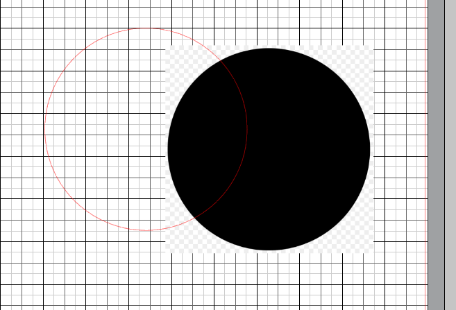
Then, I duplicated the circle three times and layed them out in a cross formation.
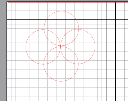
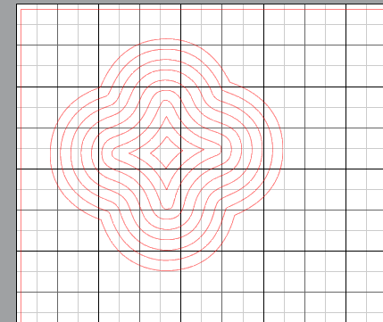
Because of petal-like shape each circle overlap formed, I decided to use the welding tool to form my clover shape. After, I created several offsets internally and externally.
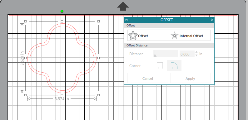
Finally, I grouped the outlines together to make this:
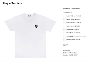
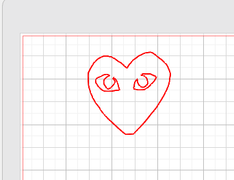
Comme Des Garcons Heart
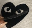
I decided to recreate a Comme des Garcon Heart using this png.
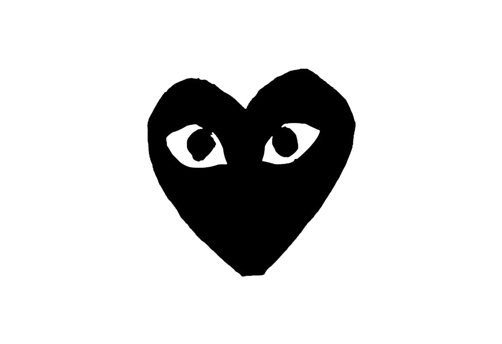
After finding and downloading my image, I uploaded it to Silhouette Cameo program like with my clover.
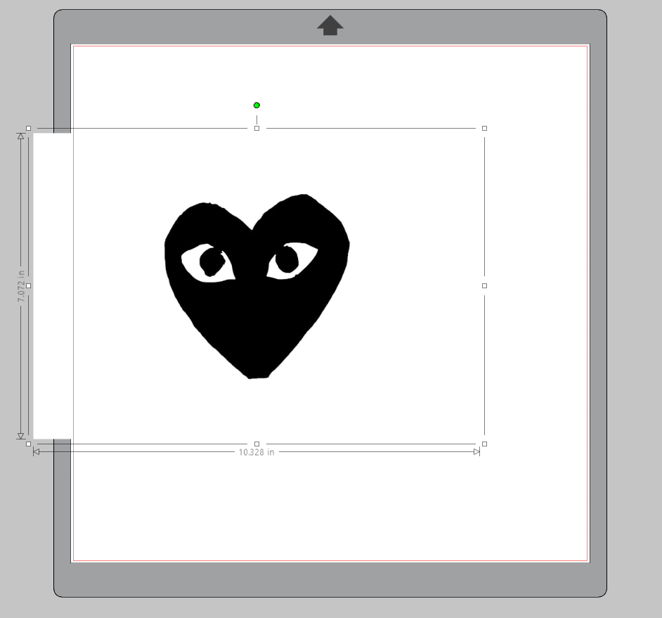
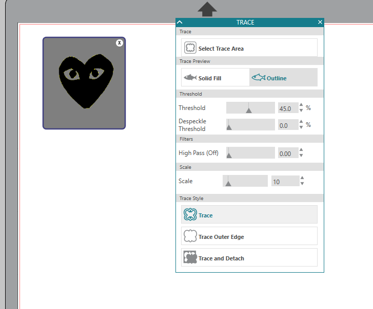
I sized my image down and then used the trace tool to outline my design.
I also mirrored my image for my hot press vinyl version.
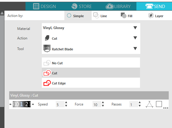
Cutting
Once my design was ready, I sent it to the vinyl cutter and choose the proper settings. (You can test cut with scrap vinyl to find the right setting, but this is what I used.)
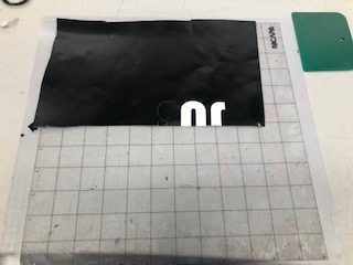
I placed black vinyl onto the cutting mat and then loaded it into the cutter. Before running my full cut, I ran one test.
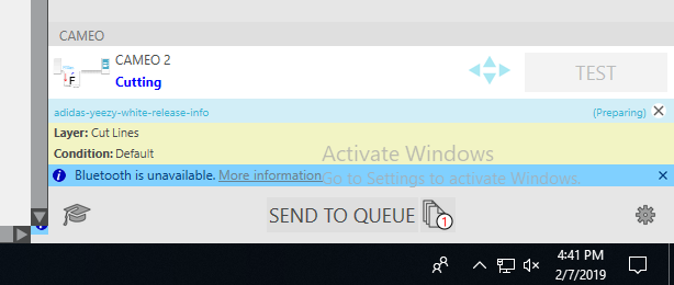
Here is a video of my heart vinyl cutting process:
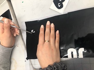
I finished my vinyl cutting by taking the vinyl sticker off the scrap sheet! This is called weeding. I didn’t have tweezers, so I used a probe instead.
Finally, I used transfer tape to transport my sticker. I demonstrated this with my clover sticker because it proved to be a better demonstration.
![]()
![]()
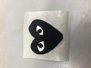
Here are my final stickers:

Heat Pressing
I cut out my design again on heat press vinyl for my shirt, but regular vinyl should work, too.
To apply the vinyl to my shirt, I used a heat press. This is the model we have at Charlotte Latin.
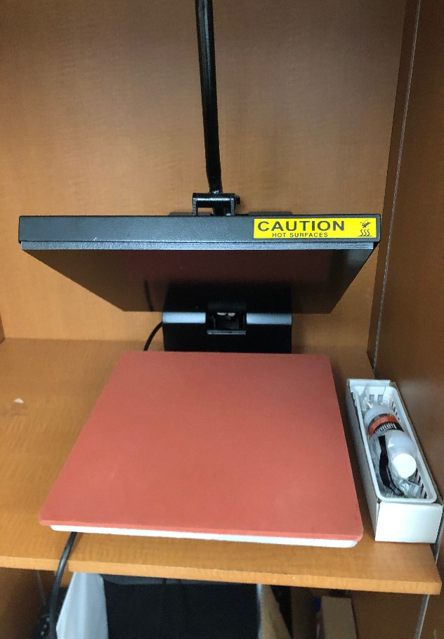
I started by turning on the machine and letting it heat up. The temperature needs to be set to 180 degrees C. After it was heated, I pressed my shirt to get the wrinkles out. When pressing, I used a teflon sheet.
Once my shirt was de-wrinkled, I placed my sticker shiny side up witht the teflon sheet over it.
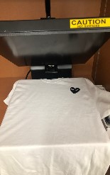
Then, I pressed for about 10 seconds. Finally, I removed the shiny part to reveal my design.
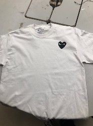
This is what it looked like:
Parametric Design
When learning about parametrics, I found this website. I found out that parametric design uses algebra and geometry to create designs. This can be helpful to change small variables in projects.
For my parametric assignment, I wanted to make an press-fit kit, animal kit, and experiment with living hinges. (I was thinking about utilizing hindges to bend the wood/cardboard around the shoulder area of my final project breastplate vest.)
Here is a video showing the progression of my parametric designs!
Press-Fit Kit
For my press fit kit, I origionally referenced this website.
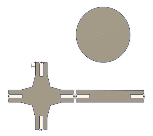
I created three basic shapes for my parametric design. My cross shape helped create 90 degree turns, the circle served as an unrestricted turning point, and the rectangles served as connection pieces.
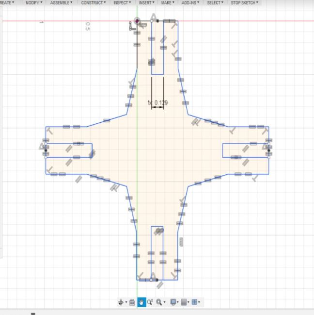
To make these shapes, I used several constraints. The most impactful constraint was my thickness parameter. Using this, I could alter my tabs. I also used an equal constraint in cordination with thickness so I would not have to type in the parameter every time. Finally, I used parallels to make my shapes more regular. (In my animals below, I used the parallel, equal, and parameter/dimension constraints.)
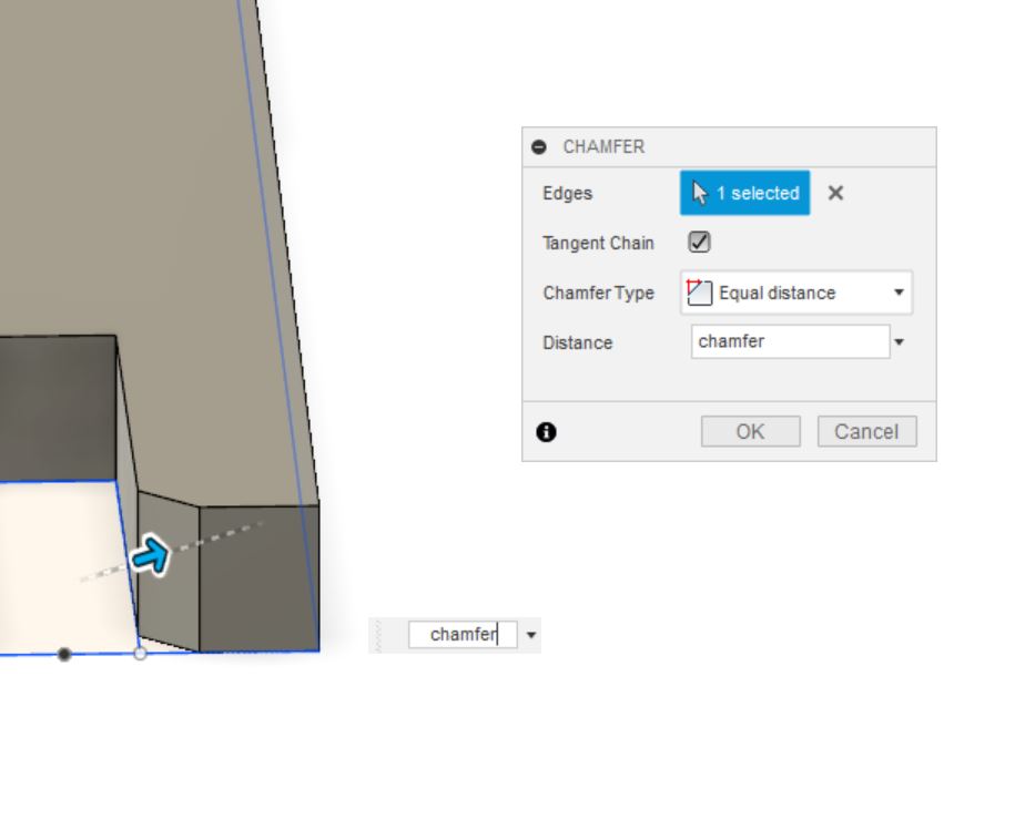
When assebling my kits I found that the pieces would slide into my slots easily. I found out from Dr. Fagan and Mr. Dubick that I need to include a chamfer in my fusion bodies.
Here is a 0.5 inch chamfer I added to my design.
Here are some assemblies I created!

Animal Kit
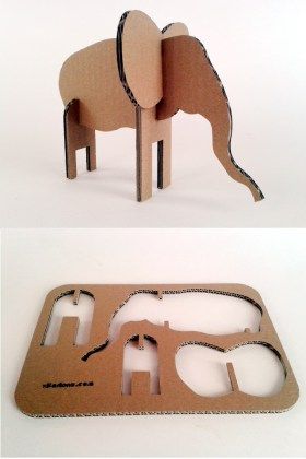
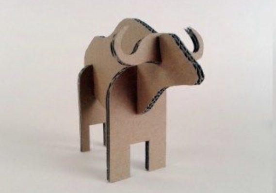
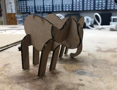
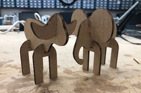
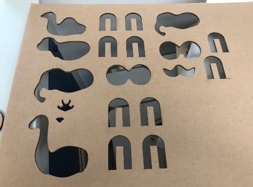
I started with the animal kit. After scrolling through Pinterest, I found these cute models that from this blog by Janusz Szczurek. I really liked his idea, so I decided to create 4 simliar figures: an elephant, a bull, a giraffe, and a camel. Mr.Szczurek had already made a few of these animals, but I decided to redesign them myself. I wanted each animal to have a different body and head attachment, but the same legs.
Here are the images I referenced.
To model my figues, I used Fusion 360. Because I had never made a laser cutting file on Fusion, I watched this video on how to make a laptop holder.
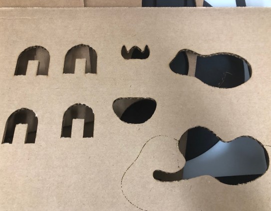
I created my animal legs first since they would be repeated throughout the project. I made the legs parallel and equal to eachother. Using an arc, I connected the two legs. After designing the basic shape, I cut a slot into the top to place my animal body into. I defined these slots with a parameter called “thick” that was based on the thickness of my material (cardboard). If I wanted to change the material to wood or double the cardboard, I could just change the parameter and instead of redesigning the entire animal. After making the back two legs, I duplicated the design for the front two legs.
I created the animal body with a spline next. I designed the body shapes seperatly. I cut a similar slot into the body at the top of the heads so I could slid in the head piece.
I made the ears for the animals last. I mistakenly made small ears for my camel. They were so small that I dropped them and couldn’t find them, so in my picture my camel is earless :(.
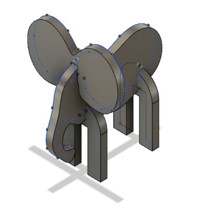
To better visualize my animals and to help with choosing sketch planes, I extruded each sketch to the parameter “thick”.
Later on, (to check my constraints) I increased the “thick” parameter to make my design thicker.
I changed the ear and body parameters and cut the new designs to test further.
Troubleshooting
- I did not use the correct slot thickness on my first design. The slots were 0.26 milimeters thick instead of 0.26 inches thick. I also did not properly center my tabs with a constraint so I could not utilize the parameters I made and instead had to redesign my animals.
- I extruded a slot in my animal bodies at the bottom where the legs were. This would not have been a problem if both legs had a slot, but it was only the front two legs. This caused my design to be unbalenced. (After meeting with Dr. Fagan, I found out that I should have just added another slot to the other legs instead of deleting the origional slot)
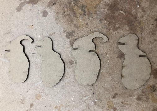
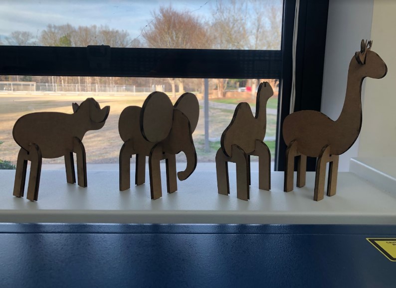
- I did not account for kerf on my third attempt. While my animals would stand evenly, their parts were very loose and volatile. I subtracted a kerf of 0.0015 onto my tabs so that when the laser cutter would remove the extra carboard, it would end up as the dimension I origionally wanted.
Here is my final product:
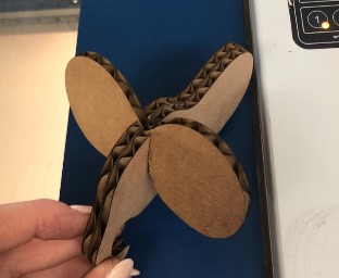
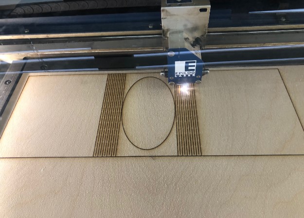
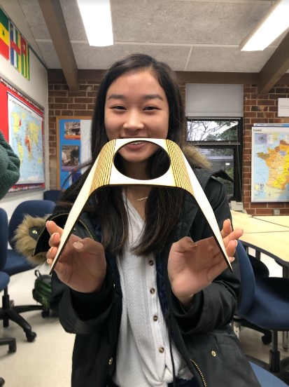
Living Hinges
To learn more about living hinges, I visited this website. From this, I learned that living hinges are designs cut into a material to make it more bendable and flexible.
When researching, I found that several designs were commenly used.
I started by drawing solid lines surrouding the area that I wanted to curve. Also, I color mapped these lines so that they would not be cut all the way through. This did not work very well. I eventually got the wood to bend to the angle that I desired, but it took an hour of bending and holding. Plus, the wood would eventually snap at the lines.
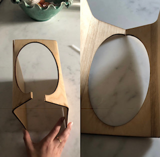
After this failure, I created the same design, but with dashed lines. Tnis worked a lot better, but it still would not bend to a 90 degree angle. Dr. Fagan explained that in the future to get a more pronounced bend, I would have to change my material or change my design.
Here is my final hinge!
Laser Cutting
When learning about laser cutting, my instructors explained and reviewed the set up, maintenance, and safety protocols. They also provided us with this presentation so we could grasp the different variables in the laser cutting process.
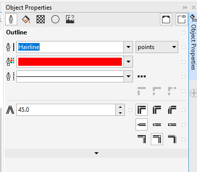
General Reminders: - 30 by 20 - Jog, red light, toggle, pencil mark on red dot - Laser cutting, top left corner - Shopbot, bottom right - Hairline - Duplicate not copy
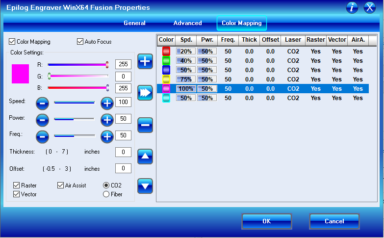
Color Mapping: 1. Pic color - Black is a reserved color 2. Click color mapping 3. Choose settings 4. Apply settings - Set the speed to fast first-slow down 6. Choose thickness 7. Turn off autofocus and focus by hand 8. Cut!
Maintenance: - Grease band - Clean Lens - Clean bottom tray
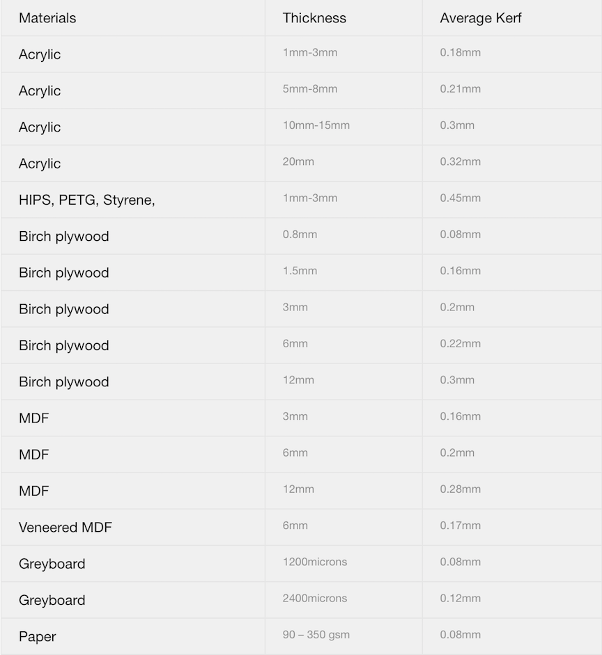
Kerf Pt. 1
Kerf is the area of material subtracted by the cutting untensil. In the case of a vinyl cutter, the kerf would be the thickness of the blade. The laser cutter’s kerf is the thickness of the laser.
To understand how this would impact my designing process, I read this article. I found that while kerf on a laser cutter was seemingly insignificant, it prevented a certain amount of detail because the pieces wouldn’t be connected well enough. Also, I needed to account for kerf when developing my slots. In the article, I found a chart that showed the average kerf for different materials:
In addition to the article, I read through this forum and found a couple, helpful quotations:
“You’d measure the kerf, and increase the size of the part you want to plug in by a tiny bit less than that.” - GrooveStranger
“Here is the thing, kerf is a somewhat subjective thing in that you have to ask just how tight do you want it? Just tight enough to hold together as the glue drys? So tight that everything stays on its own?” - markevans36301
In summery, this forum explained to me that I would basically have to subtract/add kerf onto my measurements. It also explained that implementing kerf was “subjective” and depended on how tightly you wanted your pieces to stick together. I factored a kerf of 0.0015 inches into my tab measuremnts so that they would be a little more snug, but for the overall shape of my animals, I did not mind it being a few thousands of an inch smaller. (I found the kerf of our laser cutter while working on my group assignment.)
Group Assignment: Characterize your lasercutter’s focus, power, speed, rate, kerf, and joint clearance
For our group assignment this week, my classmates and I were tasked with characterising our laser cutter.
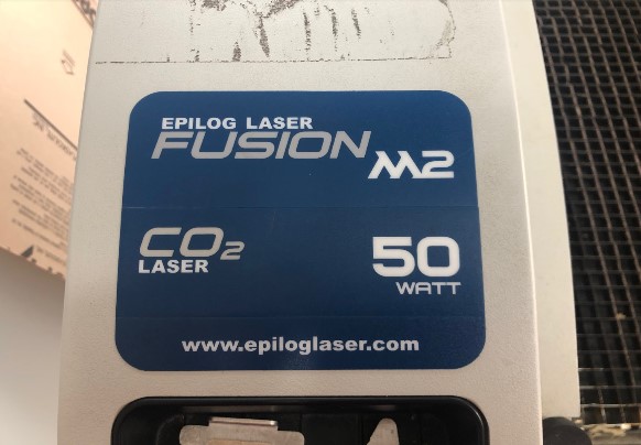
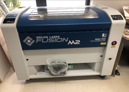
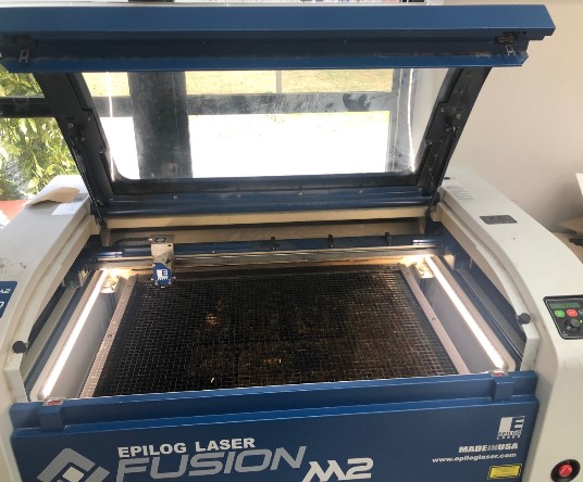
Make/Model: Fusion M2 32 / 40 Laser System (Model 13000 / 14000) - Manuel - Driver
Speed, Power, Frequency, Focus
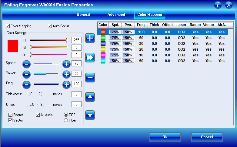
When completing my group project, my team and I utilized color mapping to test cut different senarios.

We created six identical hairline circles and changed each circle to a different color. Then, we set the circles to a variation of settings. We used six circles with one being our constant. (The black one. It was set to speed: 15, power: 100, and frequency: 10.) (For each trial, we ran the cut twice.)
Speed:
Power:
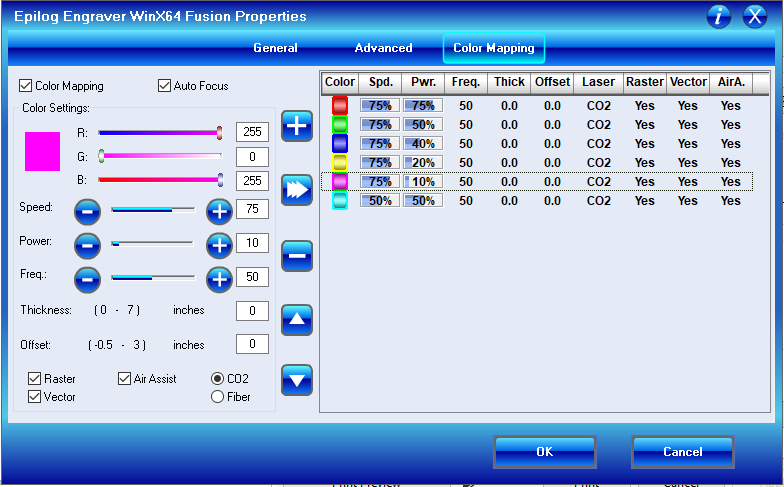
Frequency:
Here is a video of our tests:
After running all of our test cuts, we had this visual.
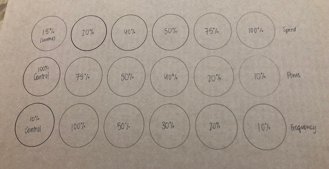
After analyzing this picture we came up with the follwing conlusions. (We noticed a few discrepancies between the “constant cut”. We are unsure why the three first circles are darker because we made the settings the same each time.)
- Speed and cut depth had a direct relationship
- Power and cut depth had an inverse relationship
-
Frequency and cut depth had an inverse relationship.
-
Speed had the most noticable effect on cut depth.
-
Power had the least noticable effect on cut depth.
-
A combonation of all three variables (control settings) proved to be the most efficient and safe. Our group found that we would get the best cardboard cut at speed: 15, power: 100, and frequency: 10. For wood, we would decrease the speed to 6.
We also found that the focus of you laser cutter can affect the quality of your cut.
These are our focusing tools, but we also have an auto focus feature on our lasr cutter.
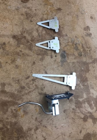
This is a comparison of a focused cut and a slightly unfocused cut! The bottom focused cut is much more consistant.

Kerf Pt. 2
To calculate the kerf discussed above, we designed a 2 inch by 2 inch square in corel draw. Then, we cut the square on our laser cutter with our optimal speed, power, frequency, and focus. After, we measured the square with callipers. We found that while our square was supposed to be 2 inches by 2 inches, it was actually a 1.997 square!
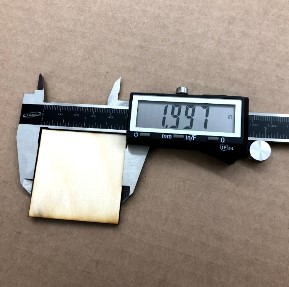
This meant that (on both sides) the laser cutter took off an additional 0.003 inches. To find the actual kerf, we divided the total loss by 2 to find the loss per individual side and found half of our kerf to be approximately 0.0015 inches. The complete kerf is 0.003, but to get exact dimensions, you would used 0.0015 to your calculations.
After discussing with Professor Neil Gershenfeld, my classmate, Maxine, actually figured out that we incorrectly identified the kerf. We should have lasercut a line and taken the measurements of that!
Manual
In addition to these physical tests, we read through the laser cutter manual quickly. This is what we learned about safety and labels:
General Precautions: - Do not take apart the door’s locking mechanisms - Do not stared directly at the Red Dot Pointer - Do not turn on the Red Dot Pointer without the focus lens - Do not cut PVC - Do not operate while the lid is open - Install and use an exhaust fan / filter unit
Electrical Safety: - Do not disassemble the machines while plugged in - Do not break any circuit connections while on
Fire Safety: - Stay next to the laser - Keep the surroundings clear - Have a fire extinguisher nearby - Utilize air assist
When adjusting a laser cutting in any unapproved way, there is a risk of radiation exposure. Maintain and clean your device regularly.
Files
Here are all my files from this week: Download Files