11. Input devices
This week, I worked with input devices! I choose to experiment with a force sensitive resistor.
Research
Force Sensors
To learn more about the inner workings of my force sensor, I looked at this site.
DIY Force Sensor
I also read this article on DIY force sensors and was inspired to create a DIY version of the sensor.
I milled two squares out of the one sided copper PCB. Then, I soldered two wires onto the plates and glued it together with a piece of conductive foam.
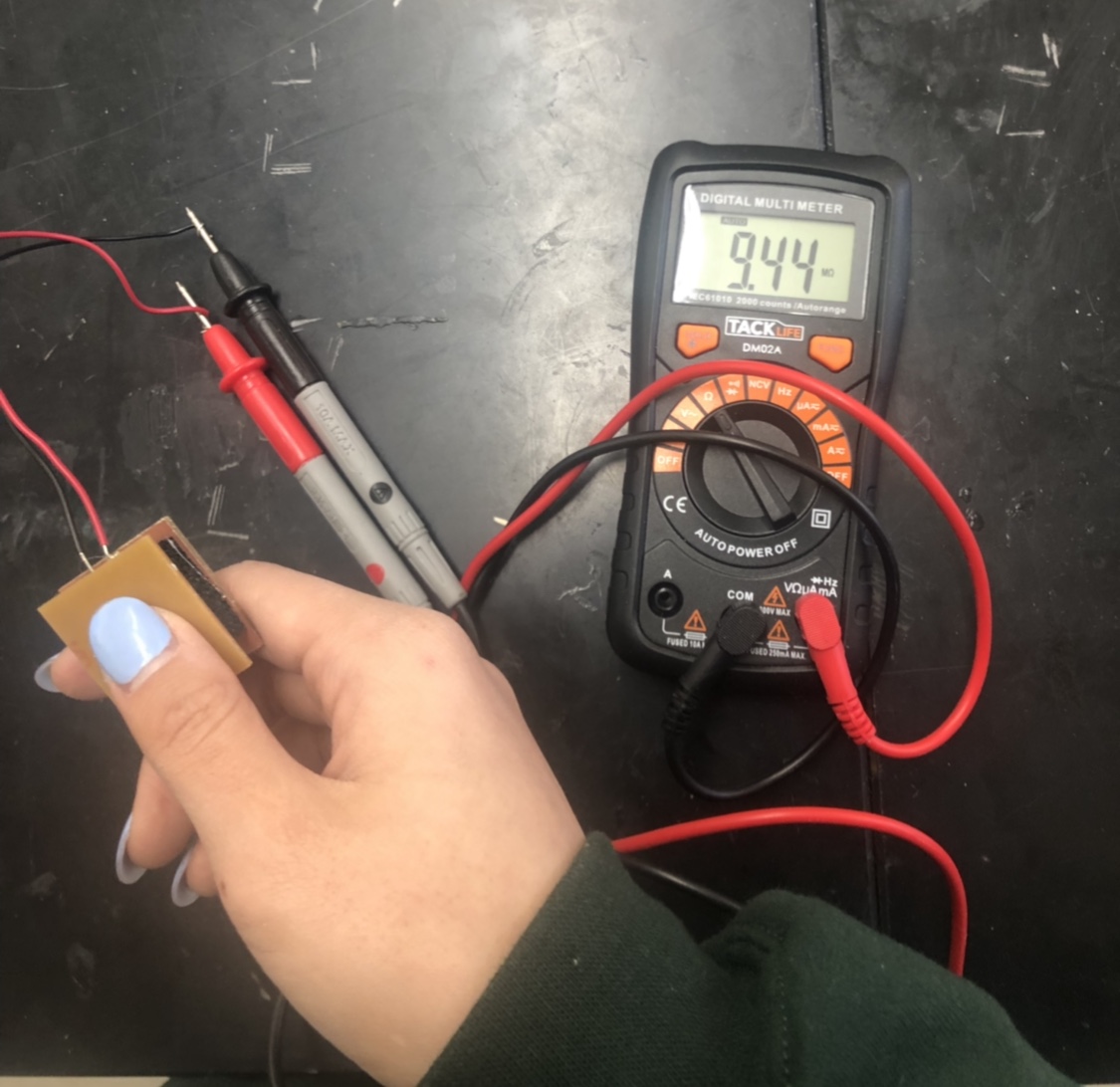
This is my finished DIY force sensor.

This is the resistance with a small amount of force.
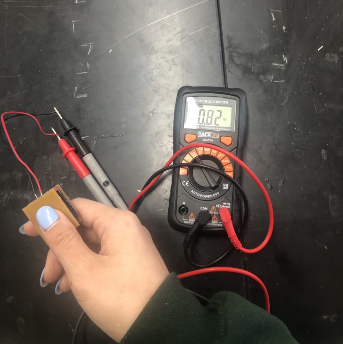
This is the resitance with a larger amount of force.
New Experiment
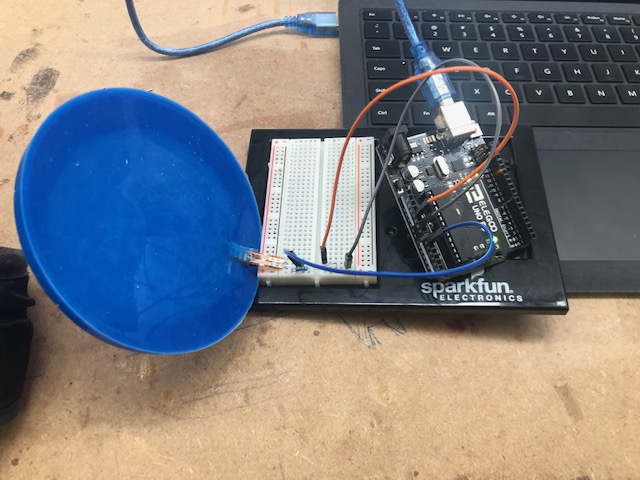
I also continued my experiments with my force sensitive resistor from week 9. Using this tutorial, I powered a LED with the force sensitive resitor.
Adapted Force Sensitive Resitor
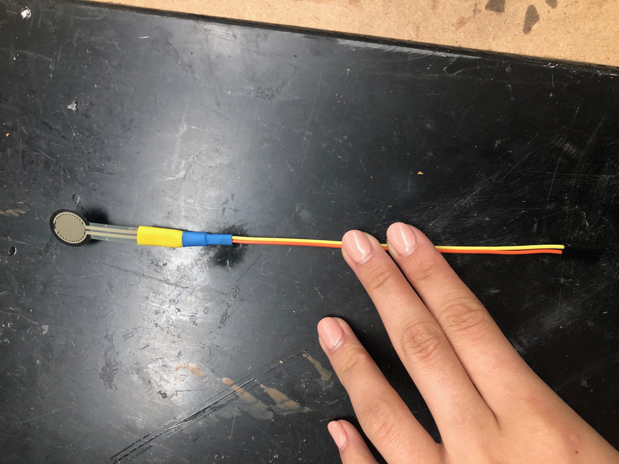
This week, I also adapted a force sensitive resistor to work with the pin headers on my board with the help of Dr. Harris.
To adapt my force sensitive resistor, I soldered the two prongs of the resistor to two female wires. (I stripped the other end of the wires so that I could solder them.) After the wires were soldered on, I used heat shrink to isolate the connections. I also used heat shrink around the prong to wire connectionto make the adaption more durable.
Here is one of my adapted resitors.
Flex Sensor
In past week, I decided to use a force sensor for both this input week and my final project, but after taking with Dr. Harris, I decided to try out the flex sensors a little more. He explained that I could mold the flex sensors into my silicon to create a better looking final product. I decided to try to create two boards for this week, one with a flex sensor and one with a force sensor.
I followed this flex sensor tutorial which I found to be similar to the setup for the force resistor.
Silicon Comparison
Once I had readings from the plain flex sensor, I tried to mold the flex sensor in silicon to see how the material would affect the values. From this initial test, I found that the silicon dampened the readings of the sensor to an extent that the values were almost un-usable. (The readings were basically bent or not bent.)
Without Silicon:
With Silicon:
I believe that the dampening effect of the silicon could have been lessened if I poured less material around the sensor. Still, I was excited to see that Dr. Harris’s hypothesis could potentially work into my design (in the future)(with a few adjustments).
Board Development
Initially, I hoped to use use some of the components from the Sparkfun sensor or resistor libraries to install my sensor onto my board.
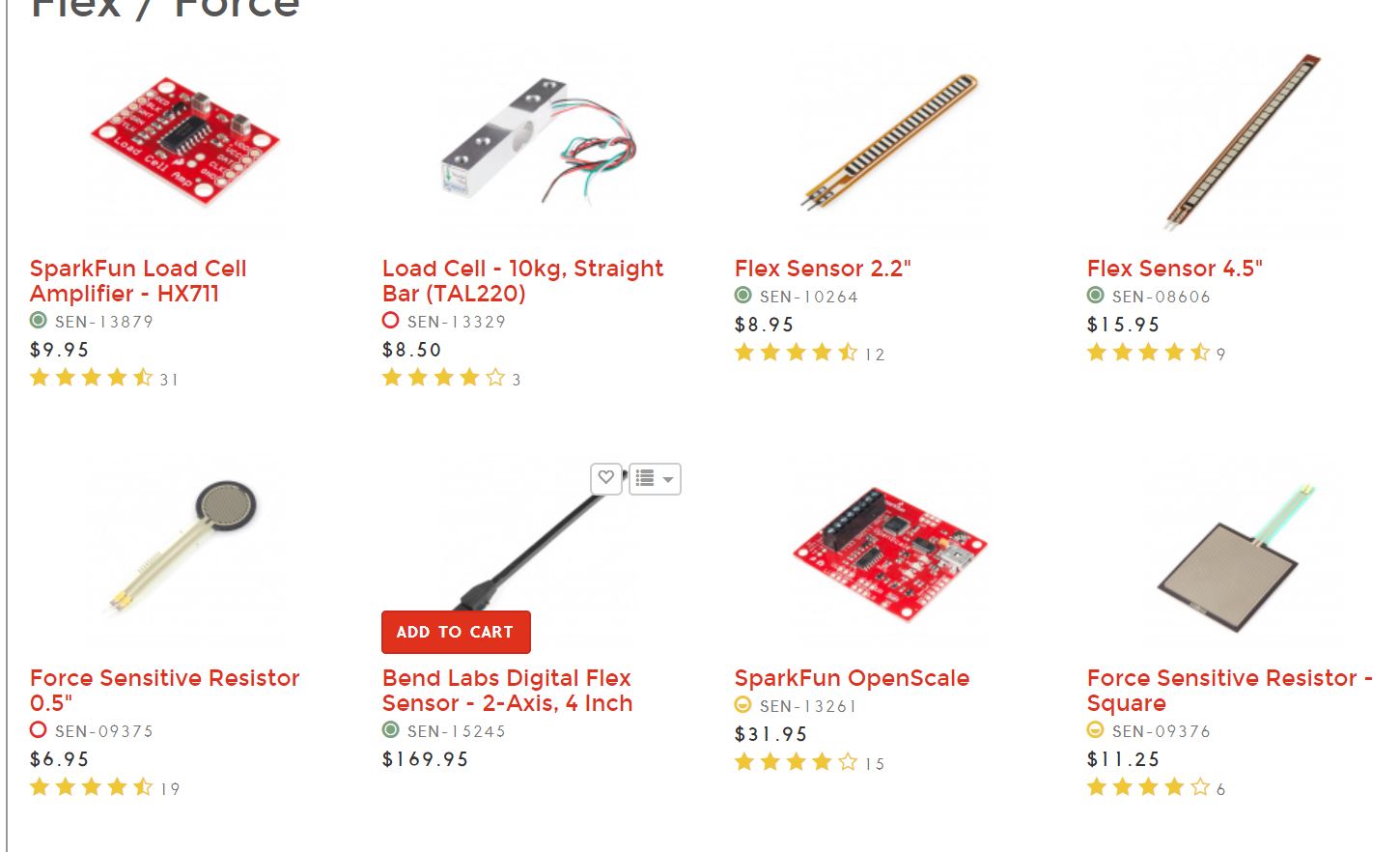
Unfortunatly, the libraries did not cover my force sensitive resistors.
I talked to Dr. Fagan who suggested that I edit a pre-existing board to start off. He recommended that I make changes to the Satshakit board.
This is the Satshakit by Satsha! (The board layout is very similar to an Arduino board.)
I decided to create a new board that would read a force sensor. I plan to reuse this board design (or something very similar) in my final project.
Changes
To make the Satshakit fit my above needs, I changed a few connections and components.
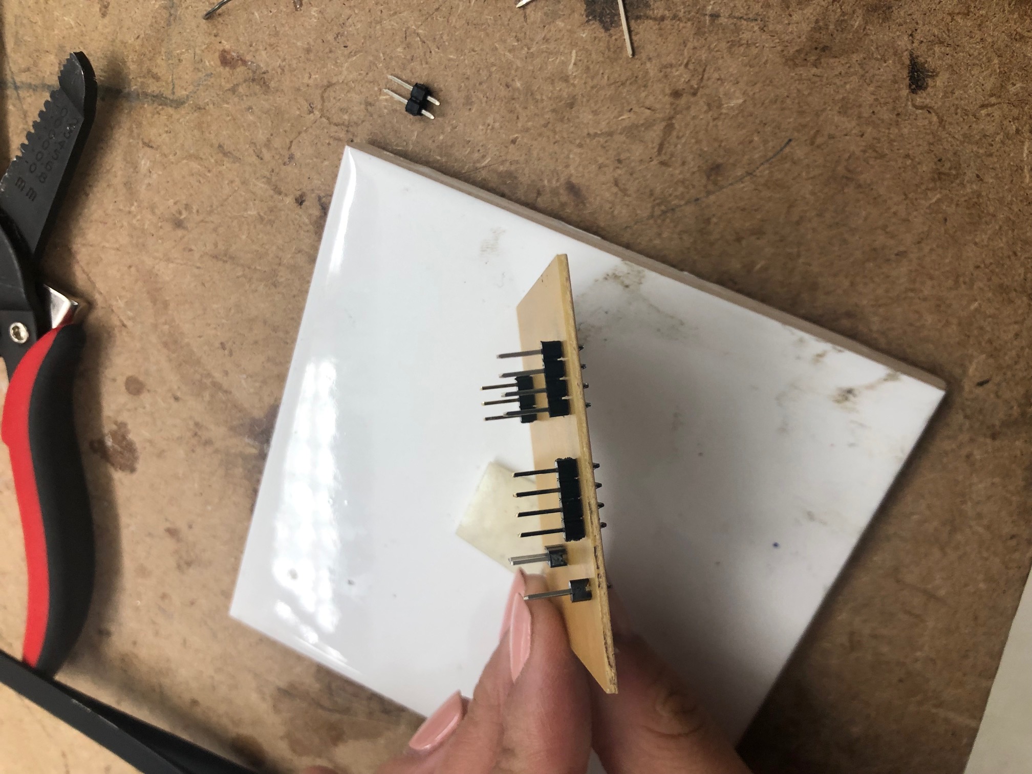
- I reduced the digital pins to three.
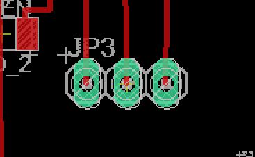
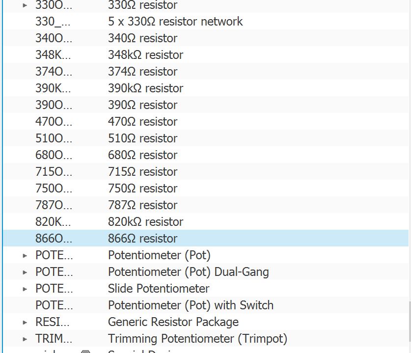
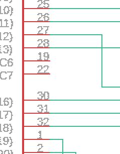
- I shorted/changed the row of analog pins at the top of the board. I only used a 4 pin header. I added the necessary resitors and power/ground connections to the 4 pin header that way I could just stick my adapted force sensitive resistors onto the pins. I did this by using two analog pins and saving the remaining pins for ground connections. I combined the power and analog pins.
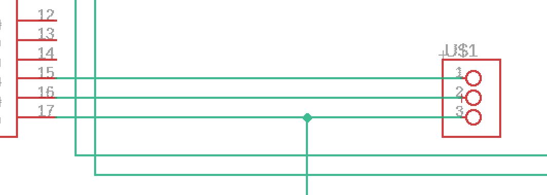
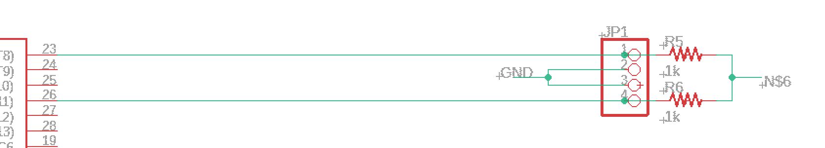
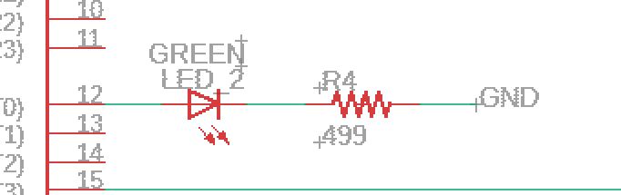
This is the sketch that Dr. Harris develop that show the connections and routings.

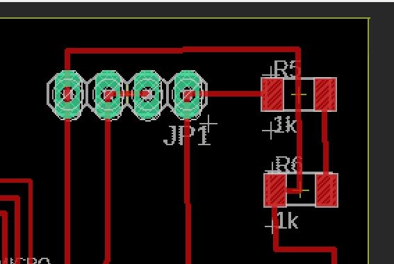
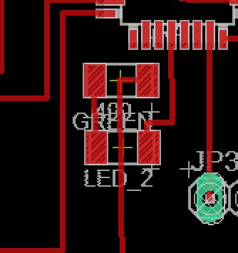
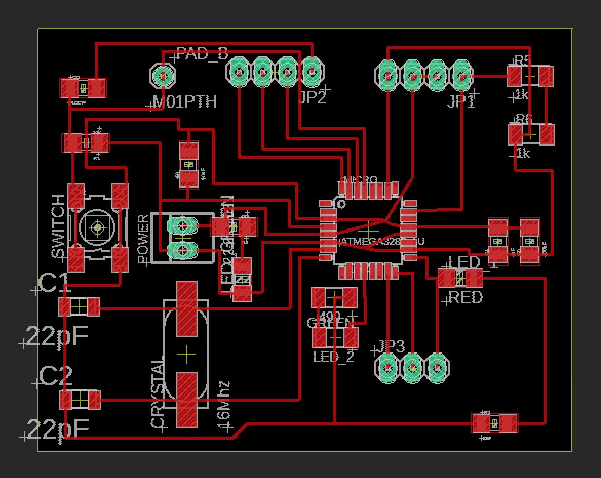
These are the eagle visuals.
- I removed the ADC pins from the board.
- I added a green LED. In the future, this would hopefully blink if the force readings were in an acceptable range for CPR.
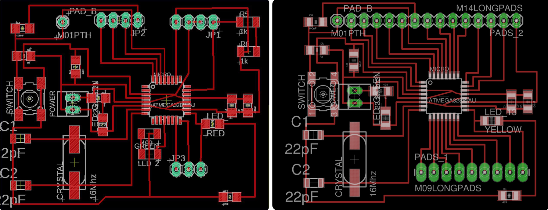
This is a comparison of my edited board (left) to the origional Satshakit (right).
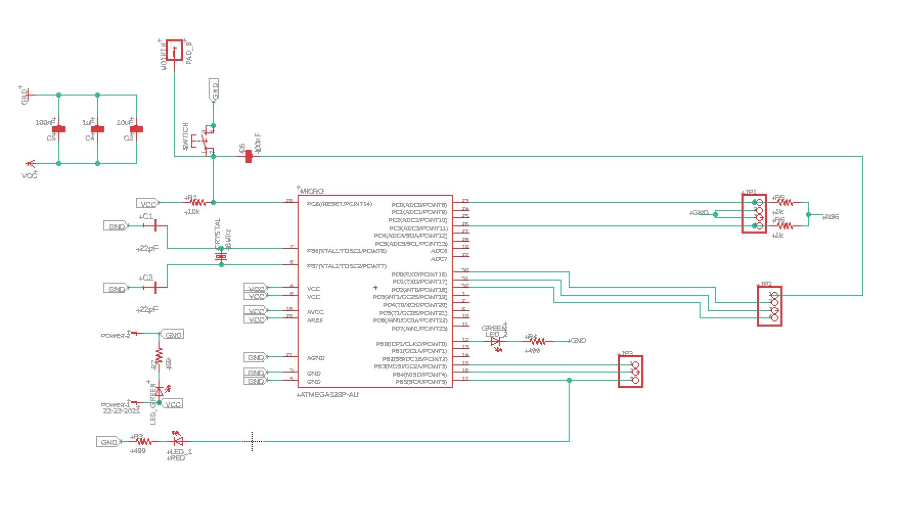
Final Board
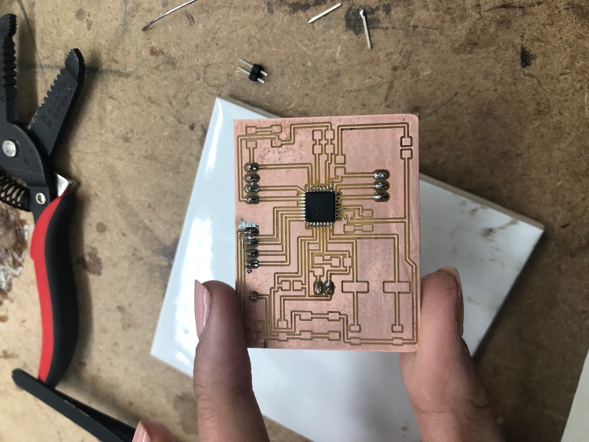
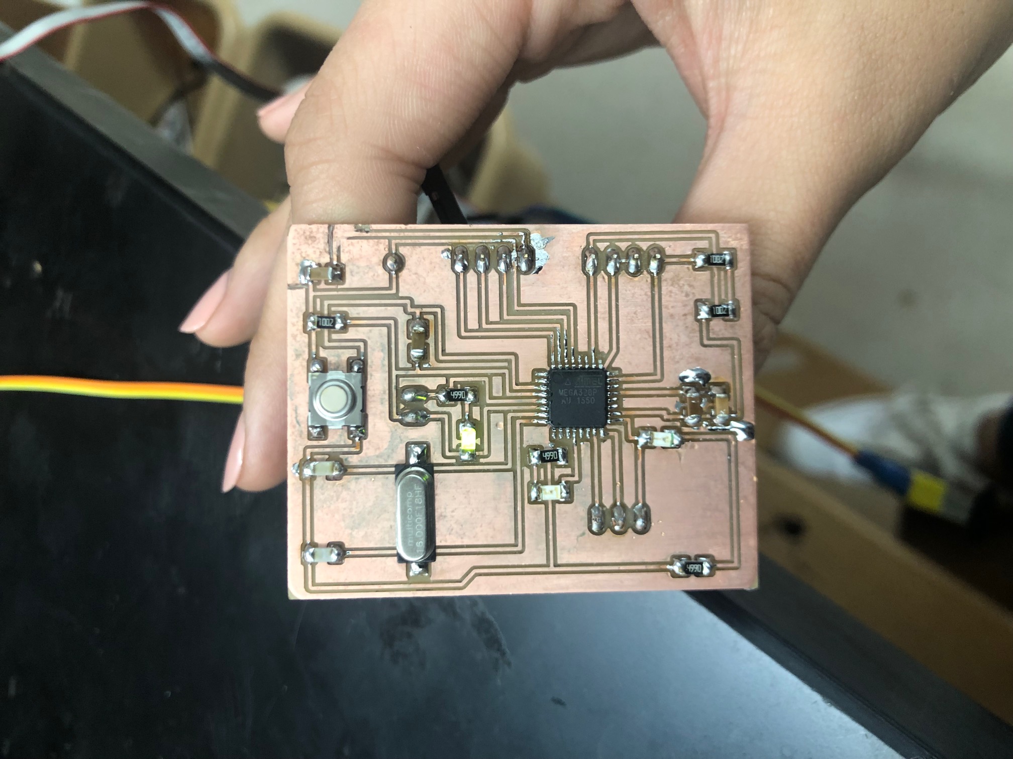
Here are the final schematic and board pictures.
Here is my final board.
Programming
Once I had my board finalized, I started programming it to read signals from my force sensitive resitor.
Here is the code that I used in week 9 from the Adafruit force sensitive resistor tutorial. I used this code to read the signals from my sensor board.
/* FSR simple testing sketch.

Connect one end of FSR to power, the other end to Analog 0.
Then connect one end of a 10K resistor from Analog 0 to ground

For more information see www.ladyada.net/learn/sensors/fsr.html */

int fsrPin = 0;     // the FSR and 10K pulldown are connected to a0
int fsrReading;     // the analog reading from the FSR resistor divider

void setup(void) {
  // We'll send debugging information via the Serial monitor
  Serial.begin(9600);
}

void loop(void) {
  fsrReading = analogRead(fsrPin);

  Serial.print("Analog reading = ");
  Serial.print(fsrReading);     // the raw analog reading

  // We'll have a few threshholds, qualitatively determined
  if (fsrReading < 10) {
    Serial.println(" - No pressure");
  } else if (fsrReading < 200) {
    Serial.println(" - Light touch");
  } else if (fsrReading < 500) {
    Serial.println(" - Light squeeze");
  } else if (fsrReading < 800) {
    Serial.println(" - Medium squeeze");
  } else {
    Serial.println(" - Big squeeze");
  }
  delay(1000);
}
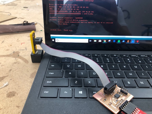
Origionally, I tried to program my board with the programmer that we made in week 5, but it was not writing the file onto the chip. I tried using a programmer that Dr. Harris owned and that worked! I believe that the programmer I have been using for the past month may have fallen victim to my backpack. (I think it was either exposed to the static of my hairbrush or just crushed.)
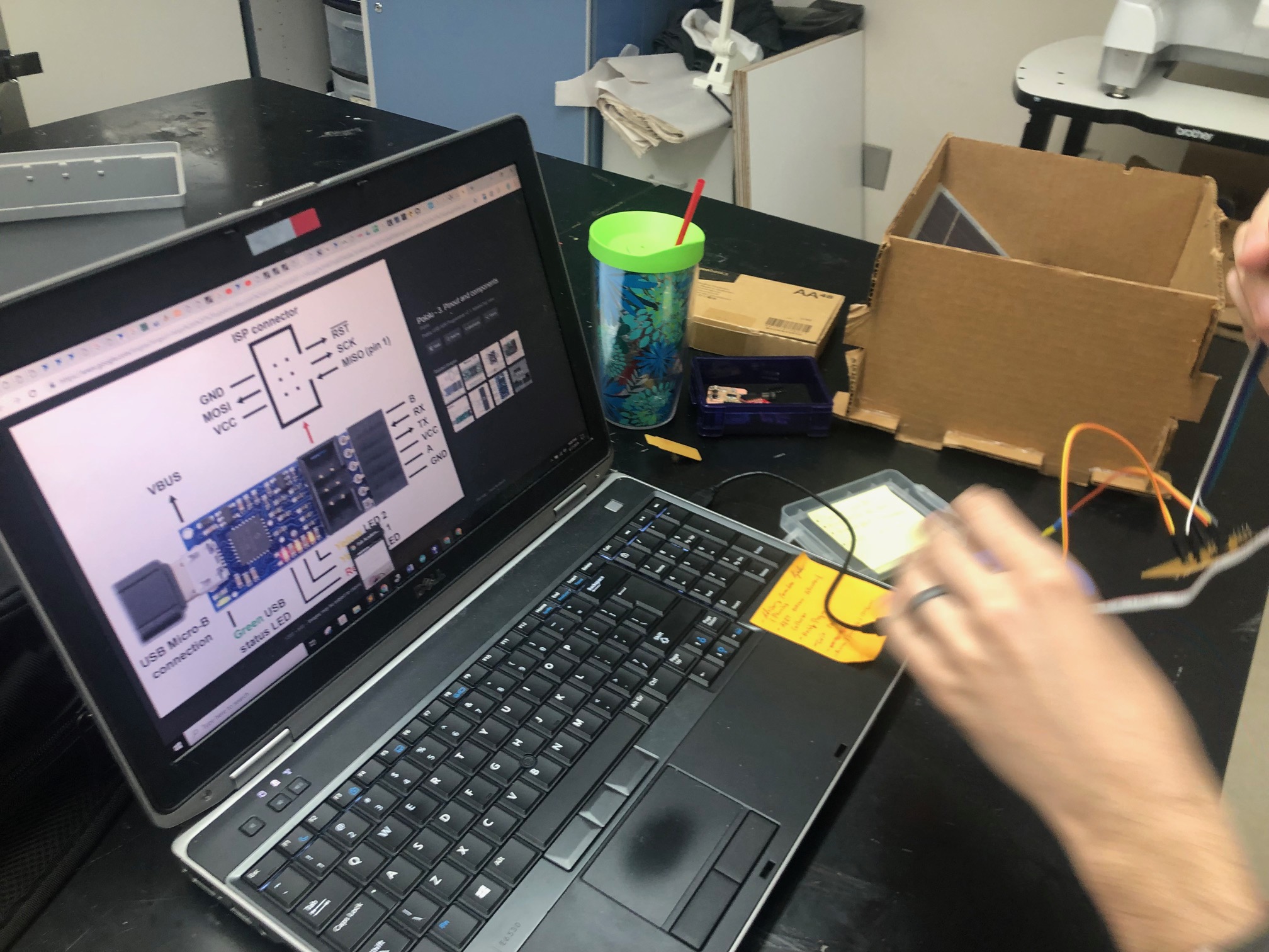
Here are the required connections for Dr. Harris’s board.
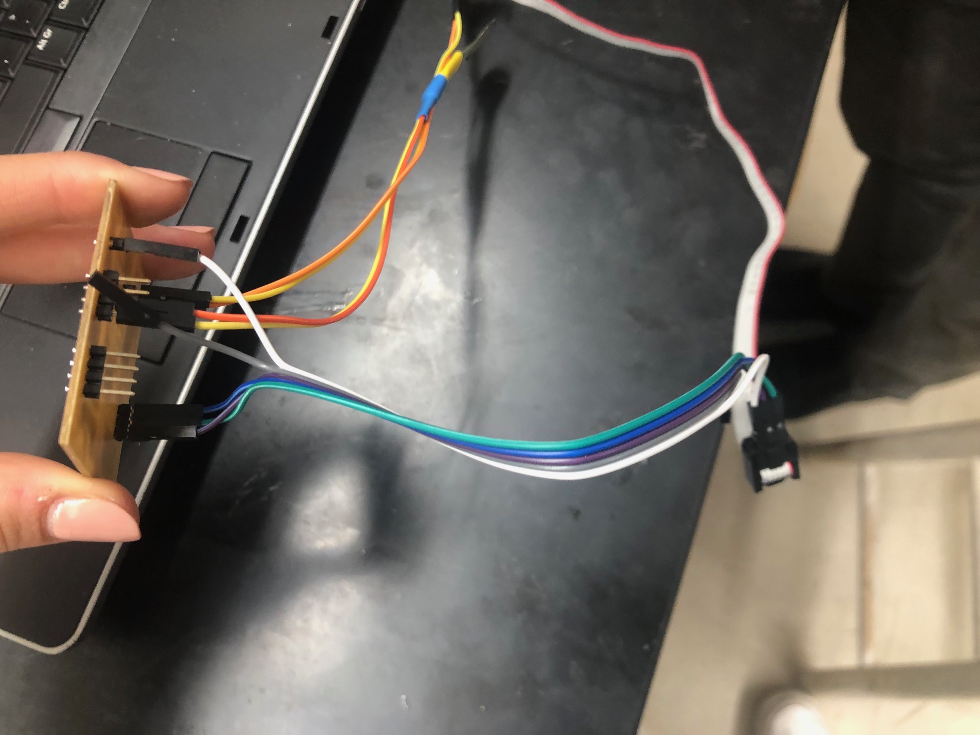
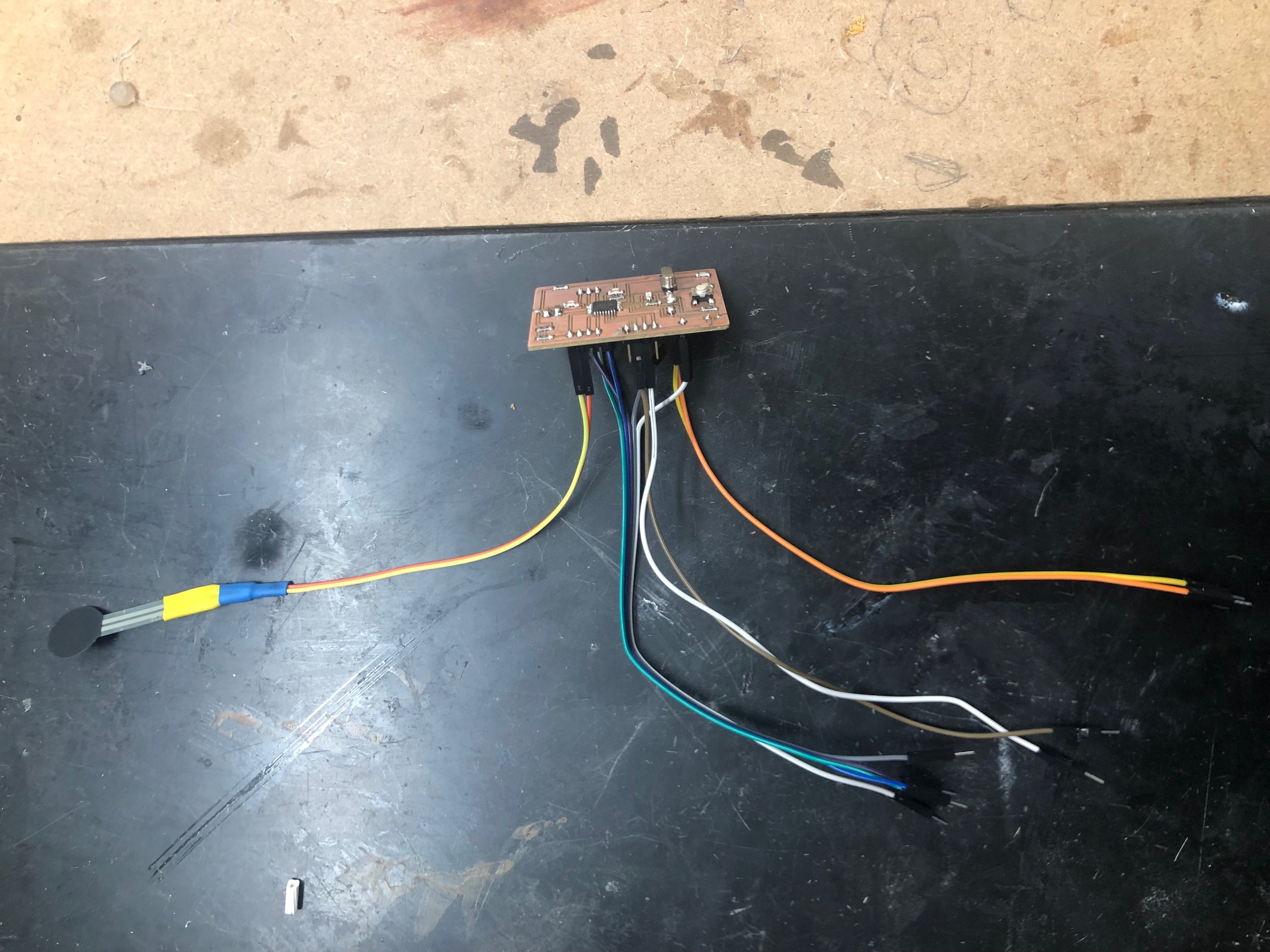
Here is how I connected my adapted force sensor to my board.
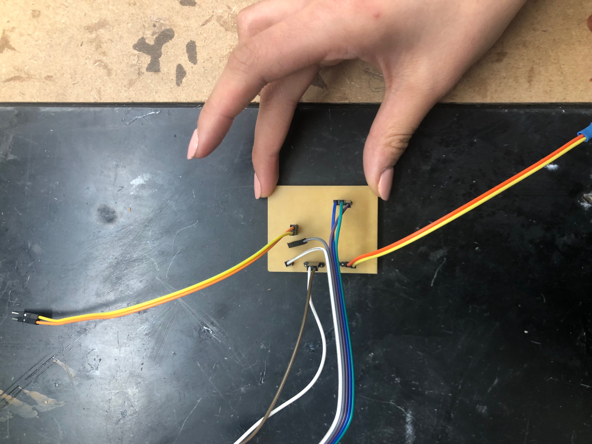
Here is my input board working!
Group Assignment: Probe an input device’s analog levels and digital signals
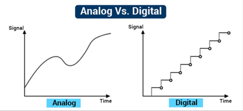
Before starting this group assignment, I reviewed the difference between analog and digital signals by reading through this webiste.
Here is a graph comparing the values of both types of input data.
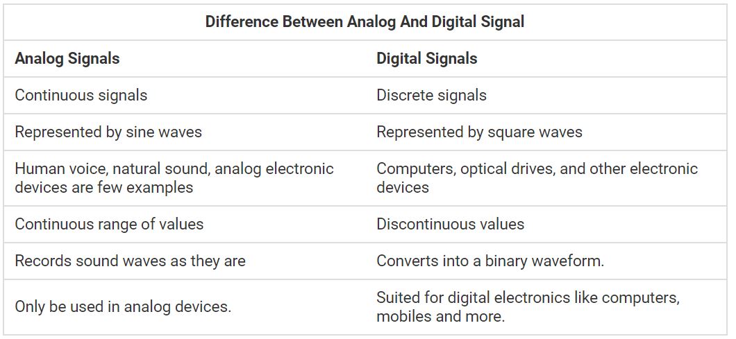
Here is a comprehensive chart explaining the general differences between the two.
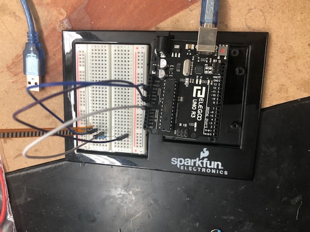
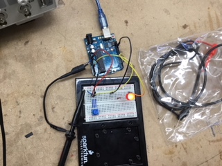
To compare the difference between a device’s analog levels and digital signals, we hooked up a potentiometer and LED to an Arduino and analyzed the values on an oscilliscope. We also looked at a slide potentiometer to see how it would affect our results.
Here is our demontration of the analog levels and the setup/connections.
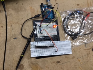
Here is our demonstration of the digital signals and the setup/connections.
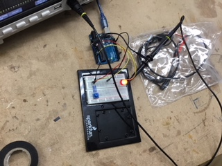
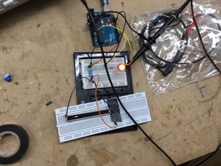
We also conducted a test with both analog and digital readings combined.
Files
Here are all my files from this week: Download Files