4. Computer controlled cutting
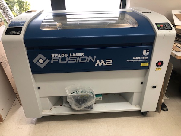
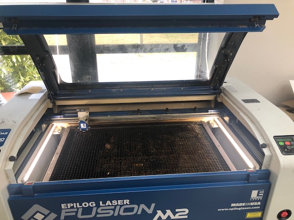
This week, I worked with the lasercutter and vinyl cutter.
I didn’t use parametric functions last week because I really didn’t see the need for it, but obviously, I must use parametric functions in my design. To review constraints in Fusion 360, I consulted this Autodesk tutorial. Then, I also looked at this tutorial to get a better idea of how this applies to 3D objects in Fusion.
Group Project
Settings
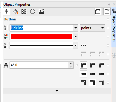
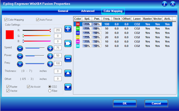
We were instructed to characterize our laser cutter, so we cut circles (diameter: 2in) on cardboard, changing the various settings to see the settings’ effects on how it cuts. We used CorelDraw and changed the colors of each circle to use color mapping, making sure that the thickness of the lines were set to hairline.
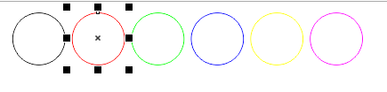
For all of these cuts, we left the black circle (first circle) alone on the standard settings, 15% speed, 100% power, and 10% frequency. First, we changed the speeds of how it was cut, speeding it up as we moved toward the right.
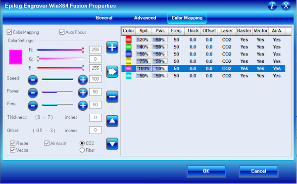
Then, we changed the power.
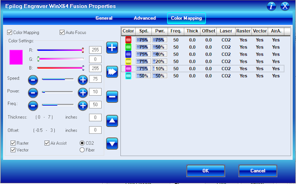
Finally, we changed frequency.
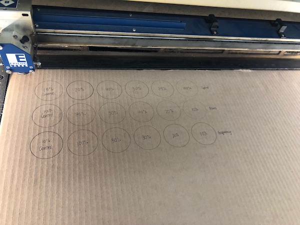
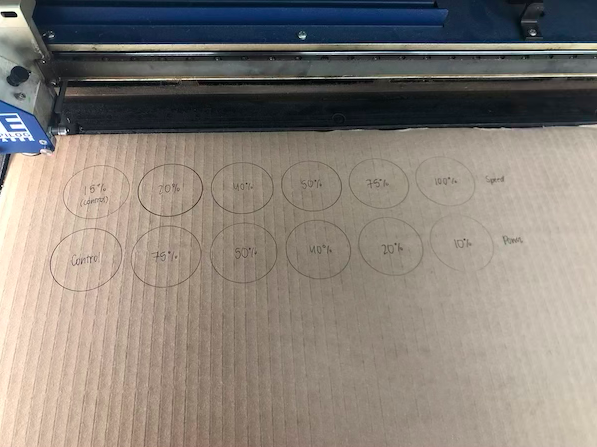
Here’s the final result:
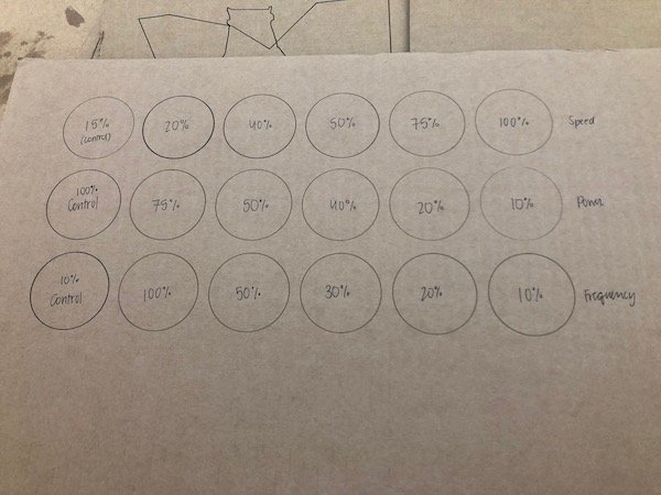
We did not touch the settings of the first circle (black) at all, leaving it at the standard settings as stated above. However, the circles look different in each row. We do not know why.
We changed all of these values to better understand what each thing actually does. For example, changing the speed yields a pretty obvious result: the laser moves slower or faster. Power changes the intensity of the laser. As seen in the 3rd row, us changing frequency didn’t really seem to alter the appearance of the circle very much. Frequency, I found out, changes the number of laser pulses per second.
You can change the settings of a laser cutter to change the results of what you’re doing. If you want to use a higher power but don’t want to burn through your material, you can increase speed so nothing catches on fire. There are various combinations of settings to use.
Kerf
To find the kerf of our laser cutter, we cut a 2in x 2in square out of plywood and then measured how wide it actually was. We needed to use a sturdy material, not cardboard. If we used cardboard, when we would measure it, it could bend and not give us an accurate measurement.
Once we cut the square, we measured it with our calipers.
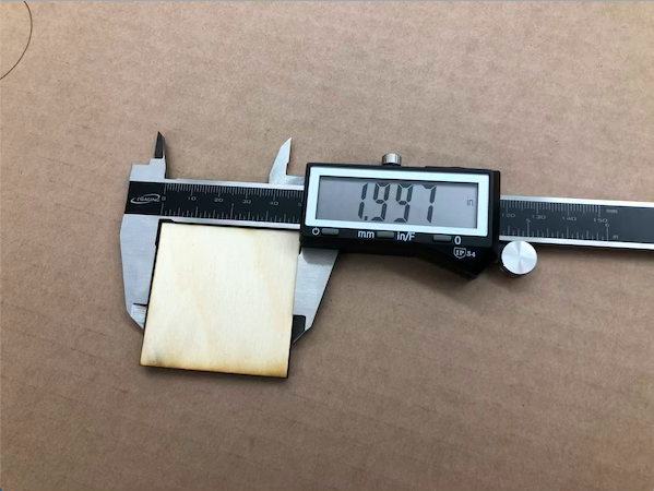
It gave a value of 1.997, meaning that our kerf is 0.0015.
2 - 1.997 = 0.003
0.003 / 2 = 0.0015
On the square, there were two cuts within what we were measuring, the right and left edges, so we had to divide 0.003 by two. When designing, however, you should add 0.003in to the design to make the design exact.
Lasercut Parametric Design
When I learned about the assignment this week, I instantly thought of this kit I bought in Japan where you take little cut pieces of cardstock and created an iconic Japanese monument. I found this image on Google, and I realized that I really want to do a little house. I decided that I would make the shape of the house first before adding elements like windowpanes and more complex architecture. I wanted to keep it small so it still has an aspect of cuteness to it. If it were really large (which I could change the parametrics for and easily accomplish), it would take up a lot of space (obviously) and no longer look cute.
However, I learned (only after designing the whole thing) that the house did not fulfill the requirements for this week.
Incorrect Design
Designing in Fusion 360
I heavily relied upon this Youtube tutorial that comprehensively shows how to use parameters to design something in a 3D landscape (like Fusion 360) and then be able to lasercut based off of this design.
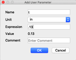
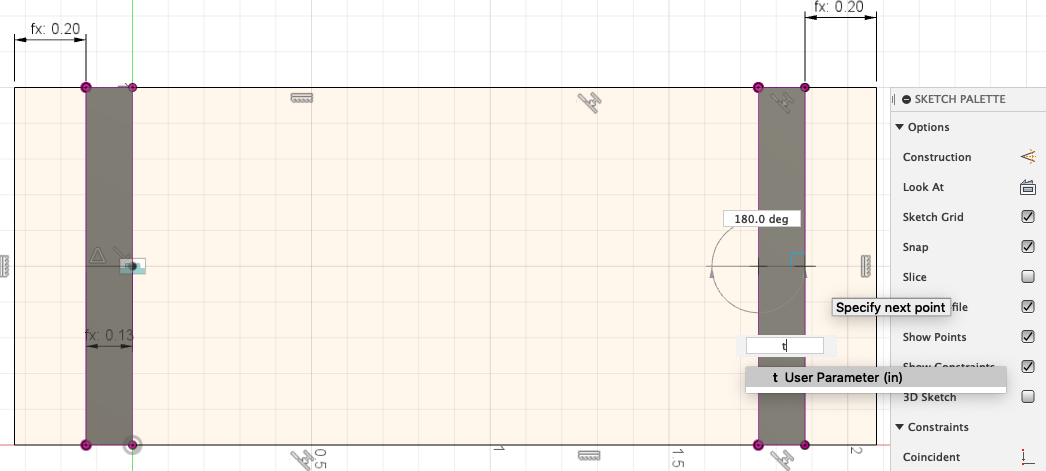
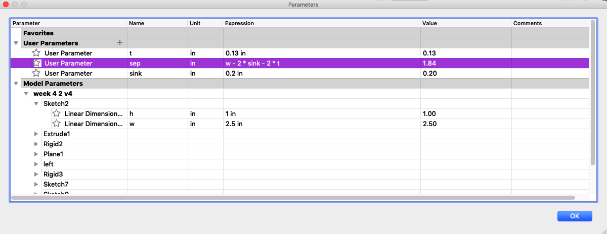
When I created my Fusion document, I first created a User Parameter underneath Modify > Change Parameters. I made a User Parameter of t, which stands for thickness. Since I cut this all out of cardboard, the thickness will be 0.13in.
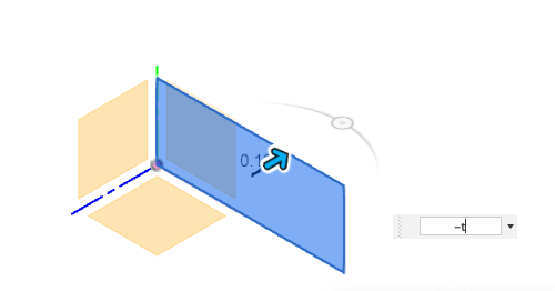
Then, I created a sketch with my desired measurements, 1in tall and 2.5in wide. Once I did that, I went back into the Change Parameters section and relabelled these two dimensions. They were originally labelled d1 and d2, and I changed it to h and w, respectively. I extruded this shape. Since I created that User Parameter earlier, I was able to extrude the shape by t inches, which was 0.13 inches. I made that body a component.
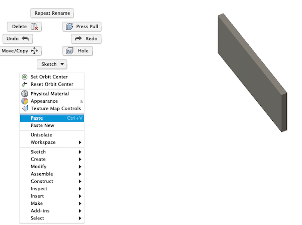
In creating the parallel side of the house (the back), I copied this component and used Paste; I did not Paste New. Paste enables the original component’s edits to be replicated on the new component. For example, if I extruded a shape out of the original shape, the same shape would be extruded out of the second shape.

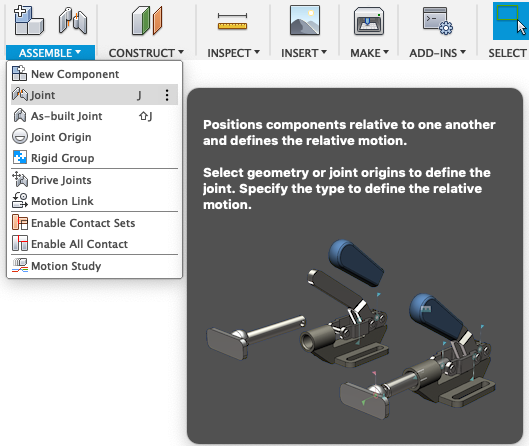
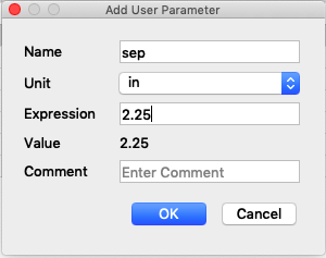
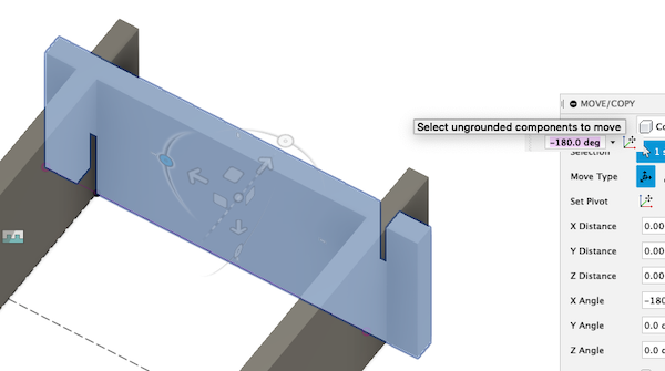
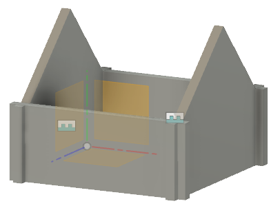
To make the distance between the two components (the space inside the house), I used Joint. I also created another User Parameter called sep, which meant how far the walls of the house would be apart.
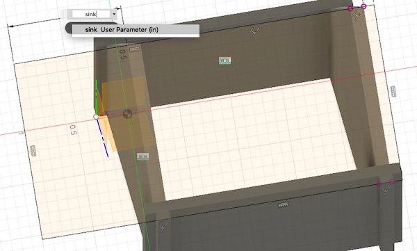
I wanted to use slots to assemble the walls and then normal tabs for the roof. To do this, I created a new User Parameter called sink, which equalled 0.2in. This parameter is how much the end of the wall sticks out after the slot. I made lines going inward from the edges of the walls with a length of sink. From here, I made rectangles with a dimension of t x h/2 so it was fully parametric. I extruded those rectangles with the cut tool, and I had my slots.
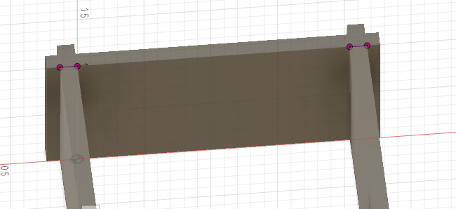
The, to create my left and right side walls, I created a new sketch on the edge of the slot and made a really rough rectangle. Then, I used the collinear constraints at the bottom and top so that the side walls would always be the same height as the front and back walls. I made the distance between the edge of the rectangle and the edge of the face equal sink, which again was 0.2in.
I followed similar steps as before to create my slots, and then I copied and used Paste New to make a new component. I did not use the Paste function because of how the tabs lined up. I needed the tabs to be on different sides, so I rotated this new component that was essentially identical to the previous; it was just rotated differently.
At this point, I realized that sep should be based off of other User parameters. I changed sep to: w - 2(sink) - 2(t). This ensured that the slots were all the same distance from the edge of each wall.
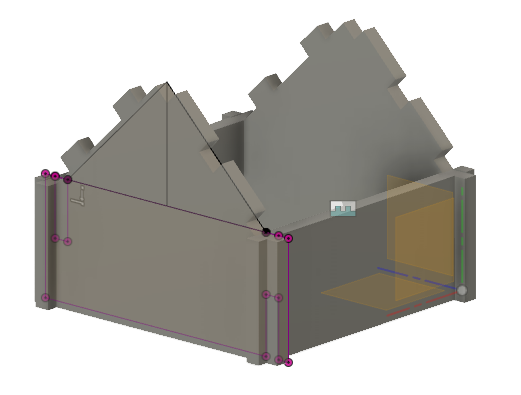
On the left wall, I made a triangle and extruded it, joining it with the left component. In this process, I used the Project tool so that I could reference points and geometry in other sketches. This became where the roof would sit. Since the right body is connected to the left component’s actions, the triangle also showed up on the other side.
To create the roof, I made a sketch on the slanted edge of the roof. Again, I made a very rough rectangle and used constraints like the Collinear Contraint. I also defined the distance from the edge of the left and right faces to the end of the roof as sink.
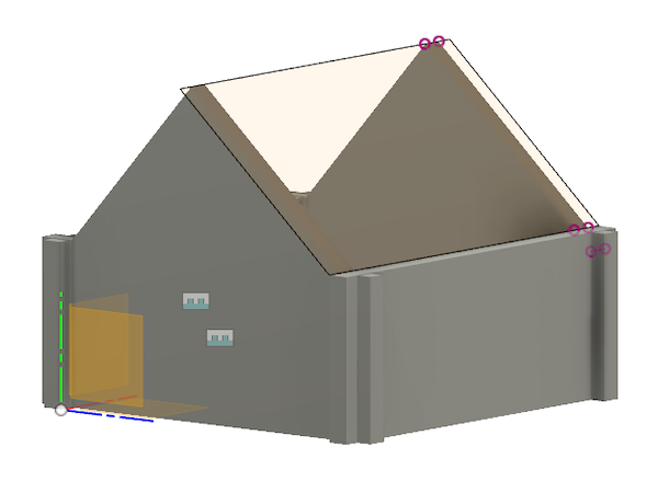
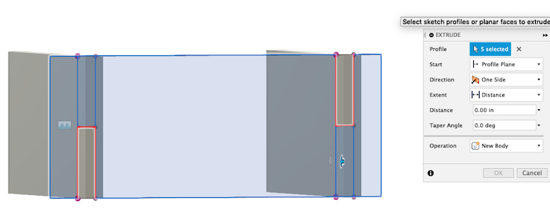
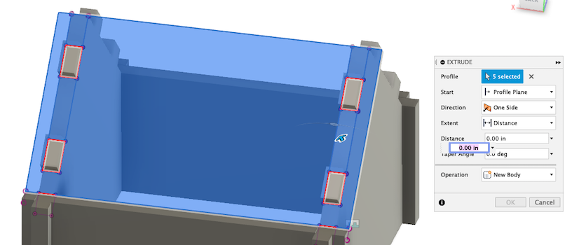
Before extruding the roof, I made tabs, which I then extruded.
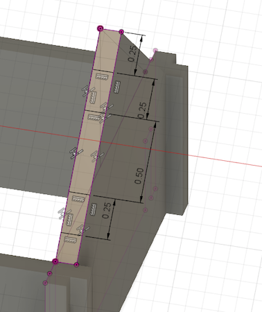
Finally, I extruded the roof tin, making sure that I did not extrude where the tabs were. I then repeated that process on the other side.
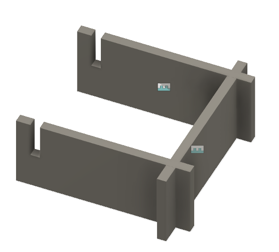
The final shape of the side
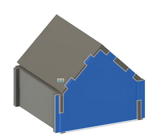
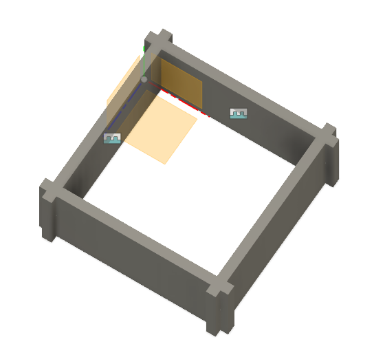
Assembled
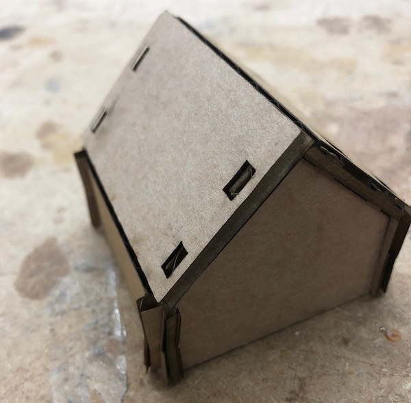
After designing this whole thing, I realized that this was not what I was supposed to be working on. The house I designed was not a press fit construction kit. However, through designing the house, I immensely improved my Fusion 360 parametric skills.
Actual Press Fit Construction Kit
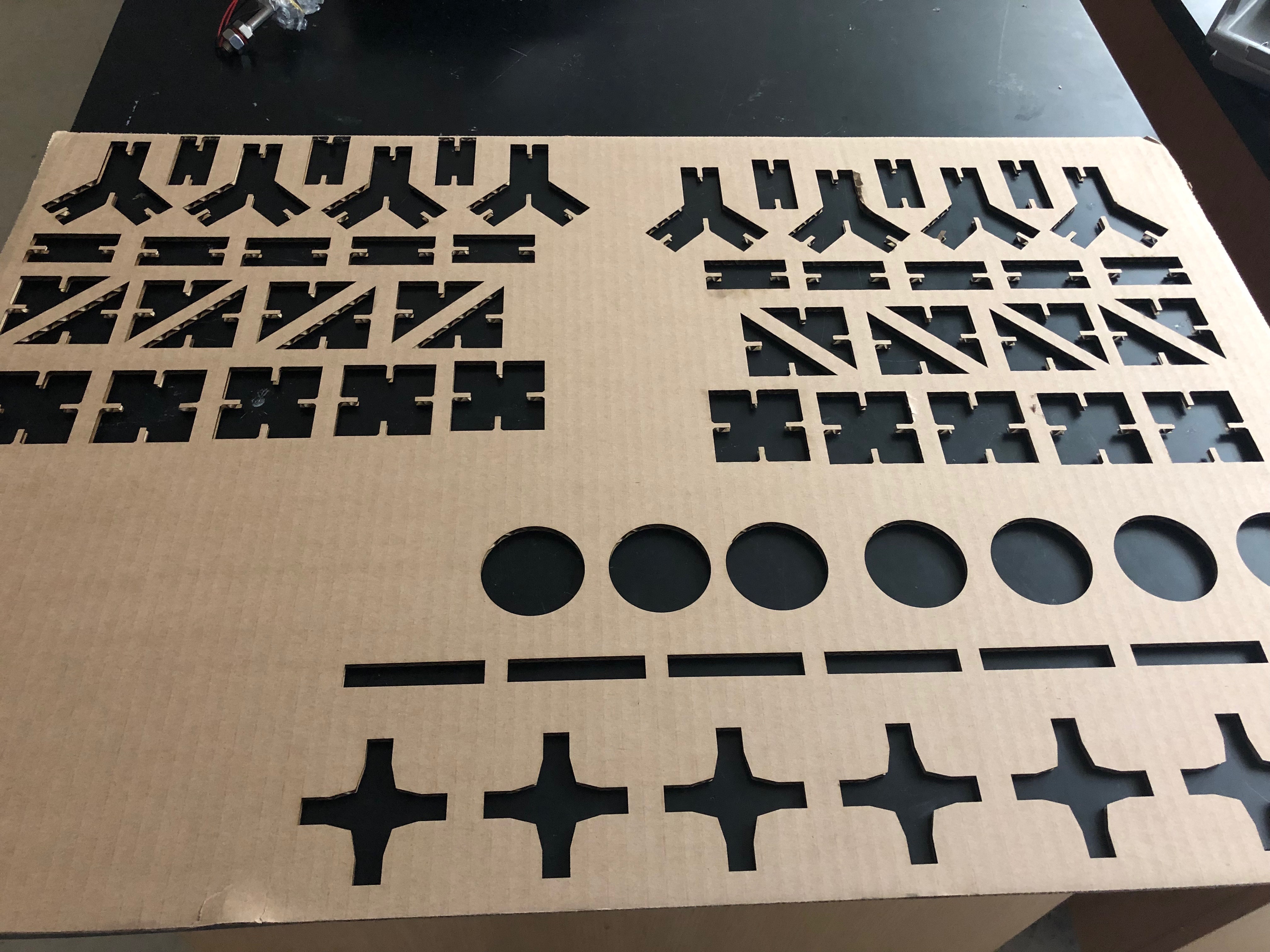
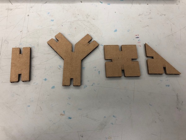
I decided to create four different shapes: a square, triangle, rectangle, and Y shape.
Designing in Fusion 360
I ensured that everything was fully parametric, meaning that I even defined the lengths, widths, and other various dimensions of each shape.
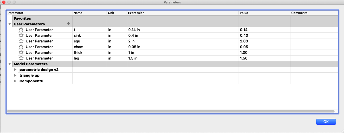
My final parametrics and variables:
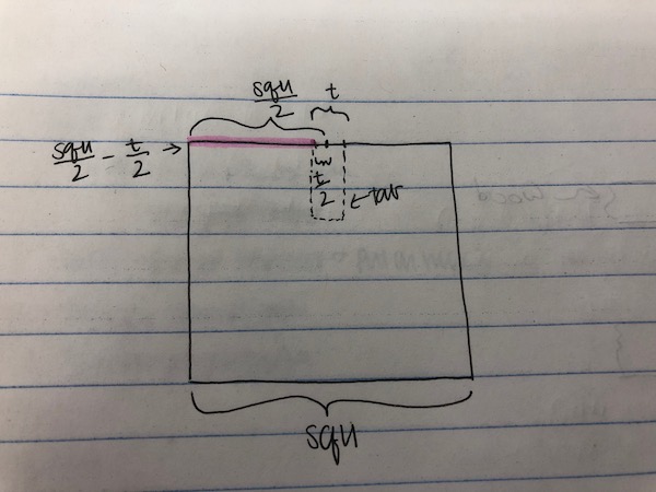
First, I made my square, which is 2in x 2in (or squ x squ). To make the tab, I made a line on the edge of the square that would center my rectangular tab. In order to make the line parametric, I phrased it as squ/2 - t/2. The tab itself is t (thickness of material) x sink (how deep the tab is).
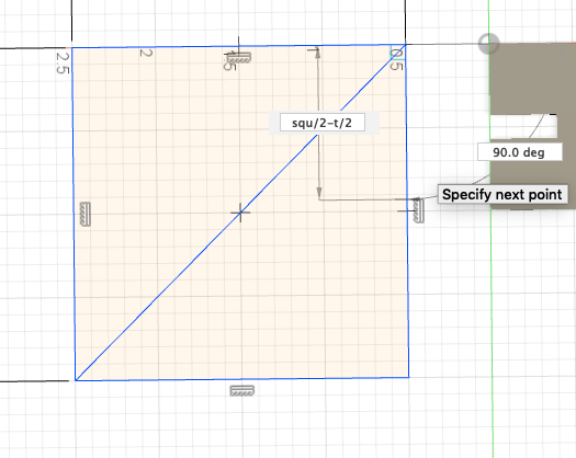
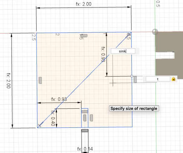
How I reasoned through the measurement:
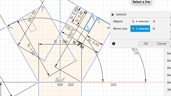
Then, to make the tabs on the other two sides, I mirrored the tabs over the diagonal line.
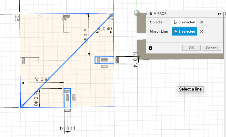
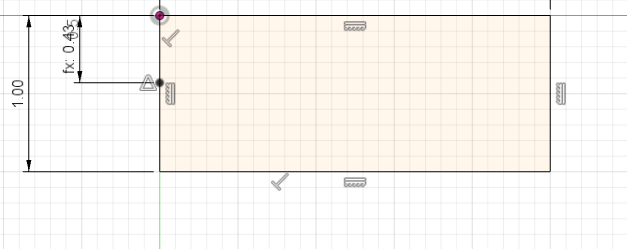
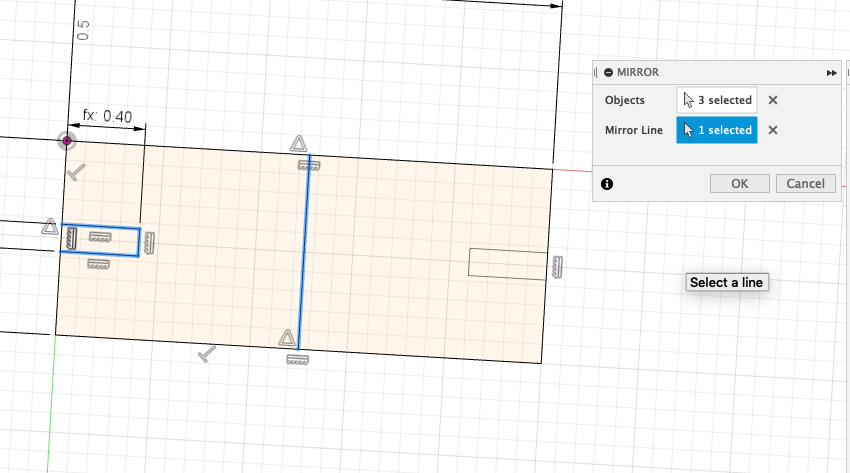
To make the rectangle, I followed a similar procedure, and my line length was thick/2 - t/2 because the side it was on was thick inches long (1 inch long). Similarly, I mirrored the tab over to the second side.
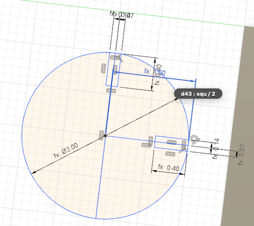
For the circle, I made a circle with a diameter of squ, or 2 inches. Then, I made a line from the center to the edge of the circle with a length of squ/2. From the point at the end of this line, I made another line that was t/2 inches long. This enabled me to create a tab off of that point and have the tab centered.
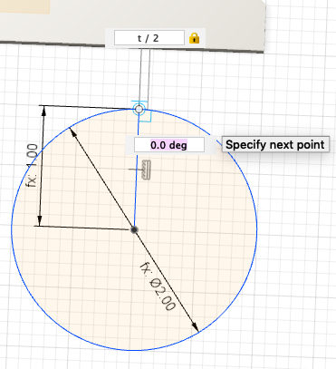
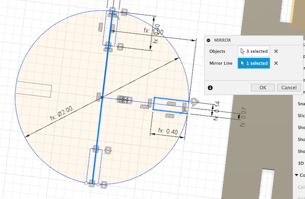
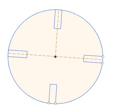
To create the other two tabs, I used the Mirror tool again. This time, I used a Construction Line.

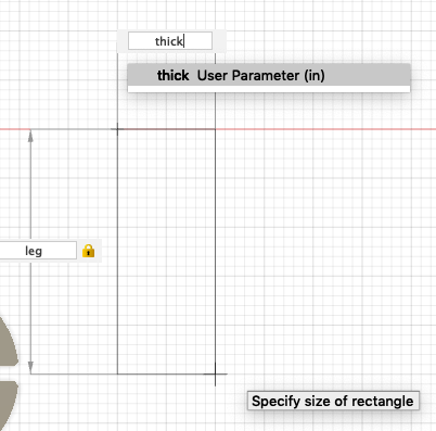
Creating the Y shape was easily the most difficult; I didn’t want to use rectangles and then have to rotate them, so I just used lines to create the whole structure. I made the first rectangle be thick x leg, which is 1in x 1.5in. Then, I created a line with a length of leg (1.5in) at a 60 degree angle. I later decided to just make it a 45 degree angle.
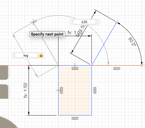
I made the second side of the Y using mirroring, including the process of making tabs.
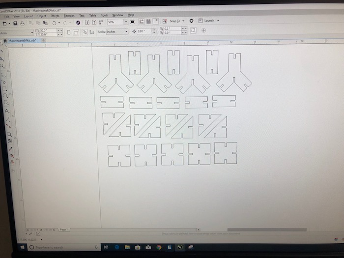
Once I had all of the shapes, I extruded them up t inches. I created a sketch off of the face of each body and saved each sketch as a DXL file. Then, I put all of the shapes on one CorelDraw document on the computer connected to the laser cutter.
Download the parametric press fit design kit
Download the parametric press fit design as a Fusion 360 file
Printing
For cardboard, I use the following settings and run the cut twice.
15% Speed
100% Power
10% Frequency
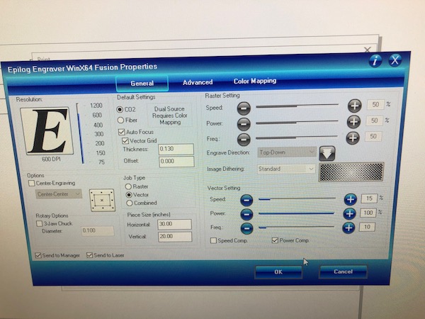
As I did during the group project, I made sure that my lines were set to Hairline. I did not use color mapping because I wanted the same speed, power, and frequency settings for all shapes. Furthermore, everything was very close together, so I did not need to use color mapping to organize the order in which the shapes printed.
They turned out really nicely. At first, I only cut a few shapes to make sure that the pieces fit together well. At that time, I used a t of 0.13. After this cut, I changed the t value to 0.14, and this was less of a tight fit.
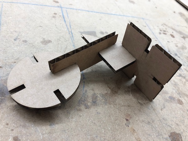
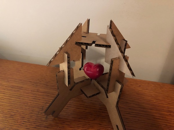
I played around with the pieces a bit, and I even made a little stand for a ceramic heart that I own.
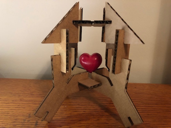
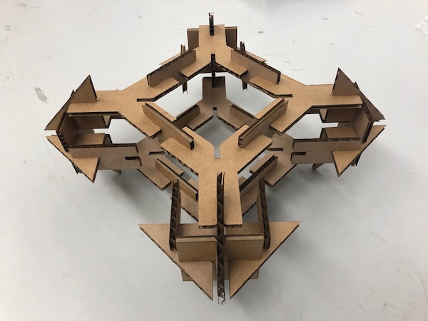
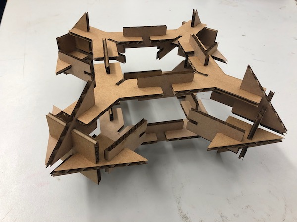
When we were at the Fab Lab, Will played with my press fit construction kit and came up with this:
I’m really happy with how the press fit kit came out, and I really enjoy playing around with it. Though I put a lot of effort into something that was not following the outline of the assignment at all, I really improved my parametric skills, along with other skills like using Modify, Joint, and Combine.
Vinyl Cutter
Silhouette Studio
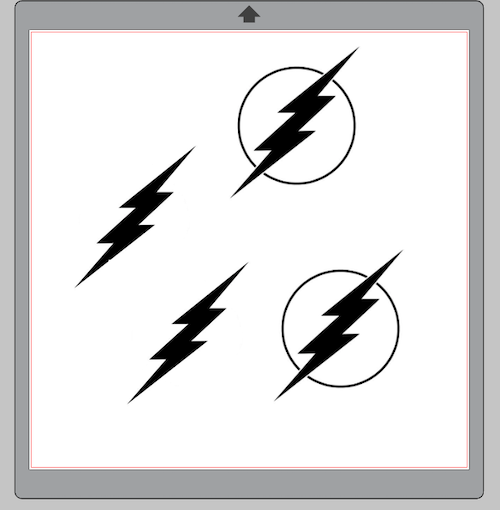
To work on the vinyl cutter on my laptop, I downloaded Silhouette Studio here. I got the inspiration for my sticker as I browsed Redbubble. I took the idea of having the different colors and altered it slightly; we don’t have that many cool colors at the FabLab.
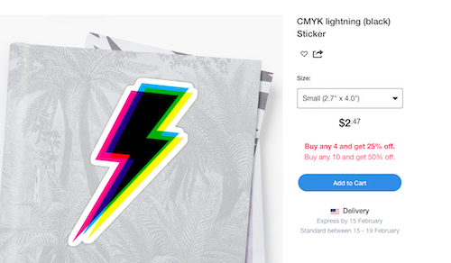
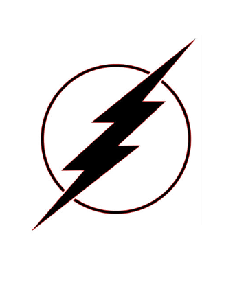
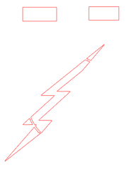
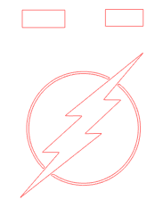
The arrow in this sticker reminded me of The Flash logo, so I went and got an image of the logo. I opened it in Silhouette Studio. I realized that I needed just the arrow to make the “shadow,” so I got the image on my iPad and went into notability. I simply used the pen tool with white and covered up the circle in the logo. I took that image and put it back into Silhouette Studio.

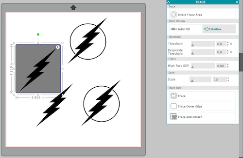
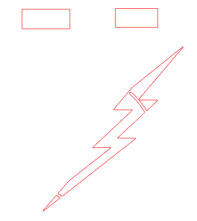
To get the outline of the logo, I used the Trace tool. I played around with Threshold and Despeckle Threshold until I got the yellow outline as I liked it. Then, I moved the gray square away from it to see the red outline that resulted. To see it even better, I moved the logo image away and just looked at the red outline.
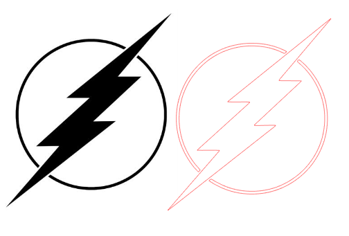
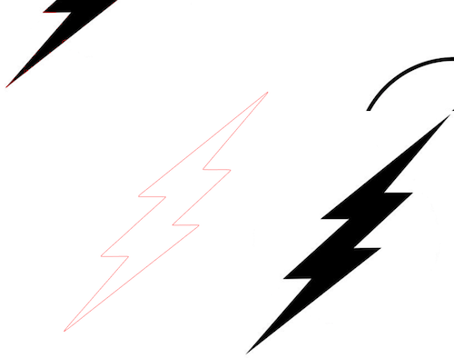
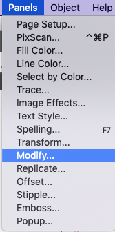
I wanted the “shadow” to be in different colors, and for this to work, I would have to Subtract the shape of one image from another. The Subtract function is under Panels > Modify. The Subtract tool subtracts the frontmost object from the backmost object selected. So, I moved the actual logo to the front and subtracted it from the bolt alone. This tutorial taught me how to use the subtract tool.
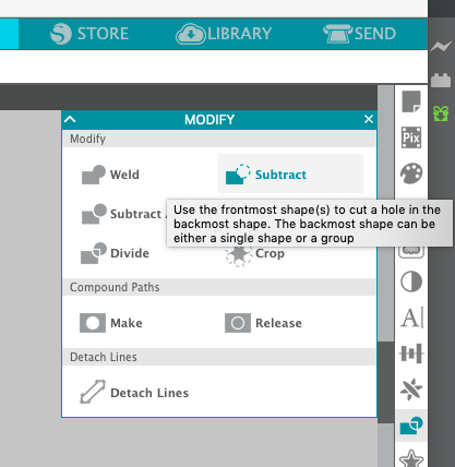
Since I wanted to do multiple colors, I watched a bunch of videos on how to align the colors after cutting them separately. The most effective method was to use registration marks, which were basically a random shape (usually rectangles) near your cut. At the end, I would line up the rectangles and the rest would line up, as well.
I found this video first, and it shows the process of physically aligning the stickers once they are cut. From this, I watched a video from a woman who used Silhouette Studio to make her registration marks. I opted not to follow her instructions and instead just draw rectangles above the design, somewhat arbitrarily. When I moved stuff around, I made sure to bring everything along at the same time so that the alignment of the registration marks stayed the same; I mainly used just normal copying and pasting to keep everything together.
I made three separate files: one for the actual logo, one for the shadow to the left, and one for the shadow to the right.
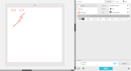
Printing
When I was ready, I went to print.
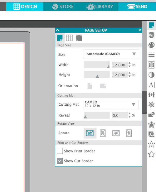
- Put desired sticker sheet on the sticky side of the mat.
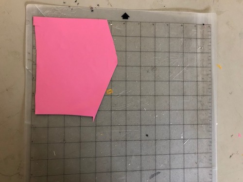
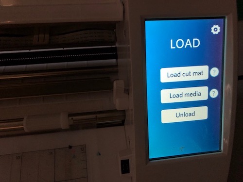
- Load the mat onto the vinyl cutter by pressing Load cut mat.
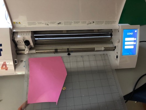

- Press Print on the computer.
When I printed it for a first time, the design was about 3in x 3in. However, when I printed it at this size, the circle peeled off; it was too small. I later reprinted it larger.
Assembly
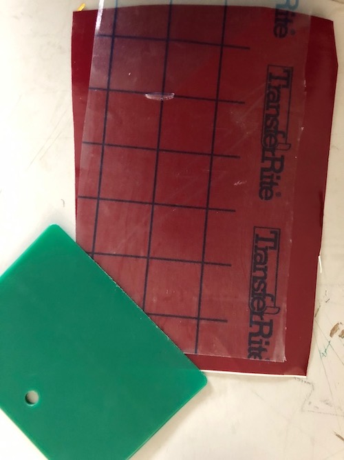
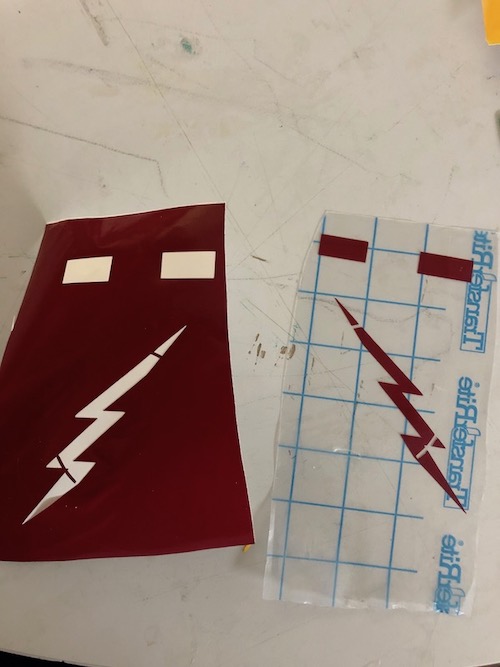
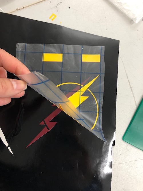
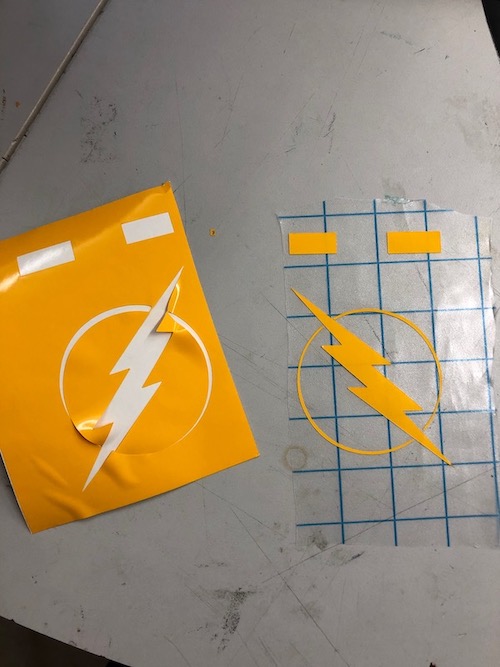
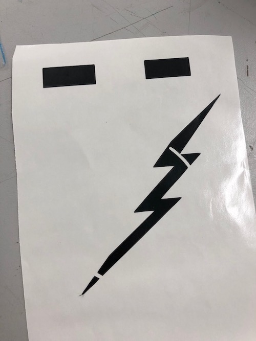
Again, I watched this video that describes how to align stickers using registration marks. However, the first time, I did it incorrectly. With this method, you are only supposed to use one piece of transfer sheet and stack all of the different stickers on that one transfer sheet. The first time I did it, I put all of the stickers on separate transfer sheets. Because of this, I had to go back and reprint my stickers.
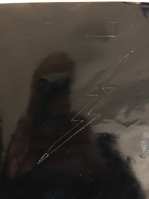
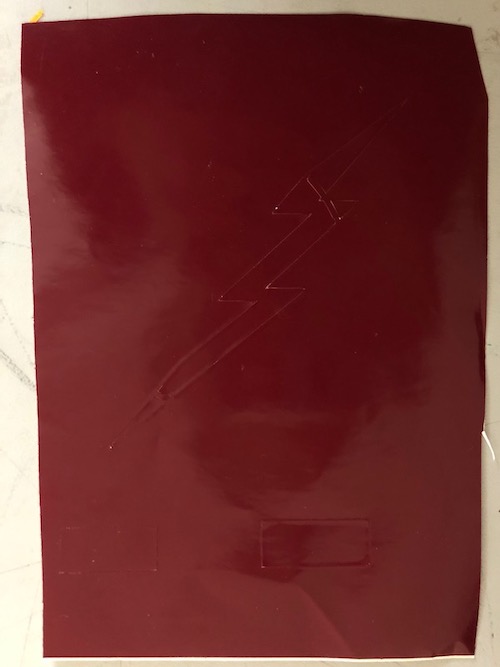
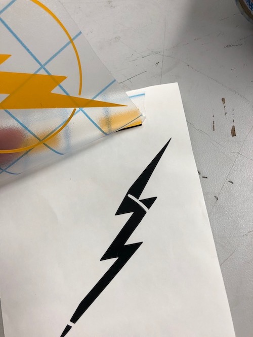
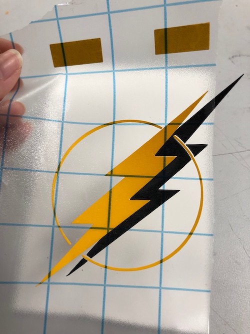
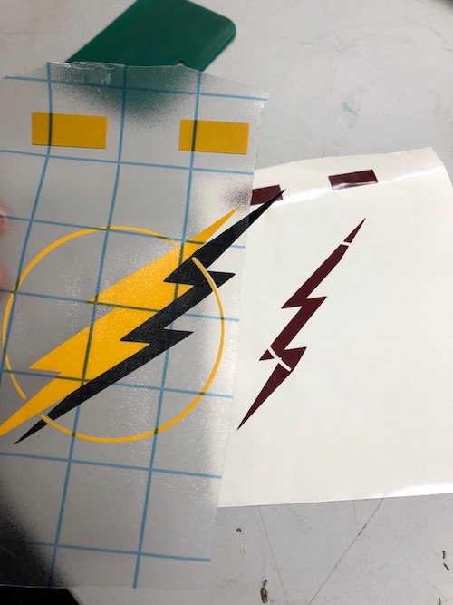
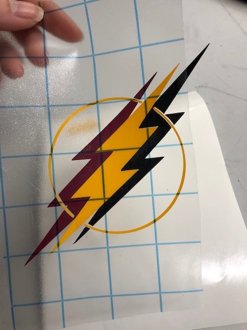
Documentation from when I did it incorrectly
![]()
![]()
I transferred all of the stickers, and at this point, I realized that I had messed up. I tried to stack them by putting some of the stickers down and then repicking them up, but it really did not work. So, I reprinted the stickers.
Doing it correctly
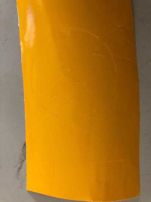
I only transferred one sticker, the yellow one, because it is the one on top.
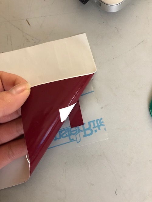
To make it easier this time, I removed the excess sticker from the sheet before picking it up with the transfer sheet.
I used the rectangles (registration marks) to line the stickers up, and this resulted in the correct alignment of both colors.
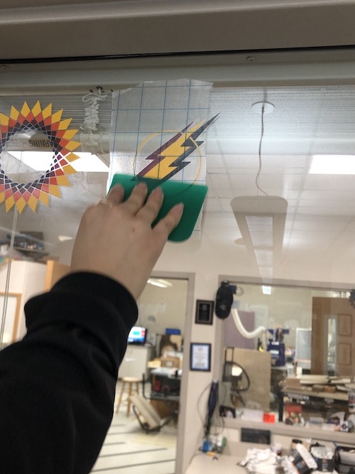
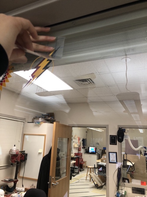
Putting it up
Mr. Dubick wanted the FabAcademy students to put our stickers up on a window after we finished. Will held a grid up on the other side of the window so that I could put it up without it being tilted. I made sure that it was really stuck to the window before peeling it off.

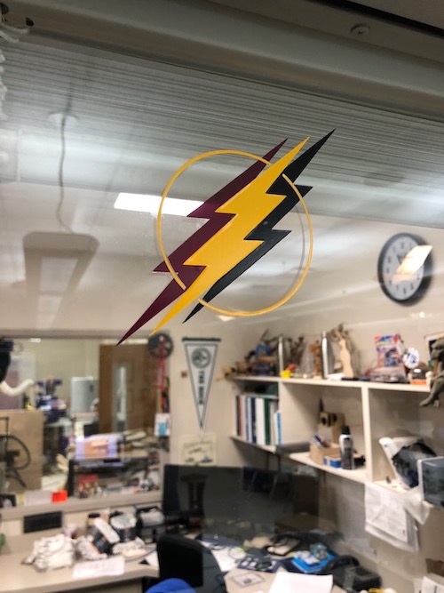
I really like this sticker, and I am proud of myself for learning how to make vinyl stickers with different colors using registration marks.