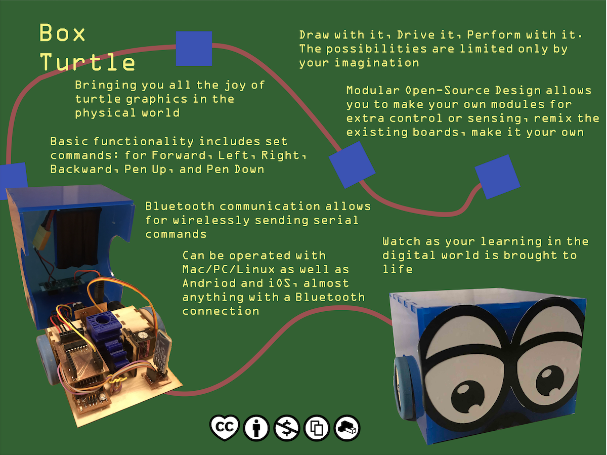
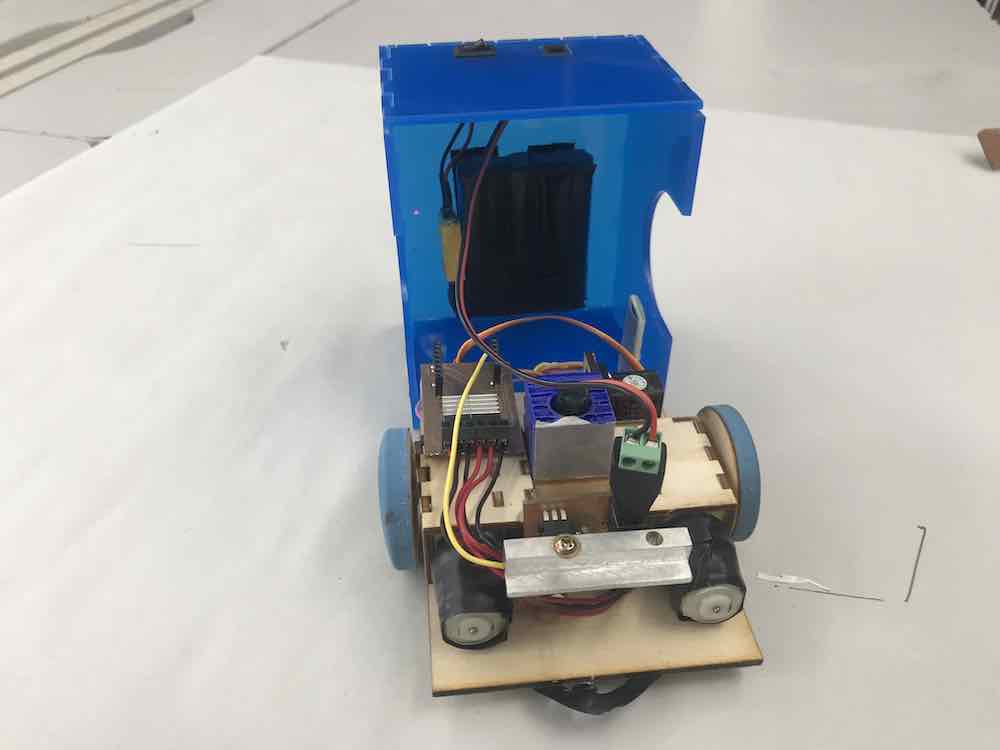
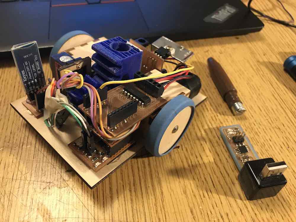
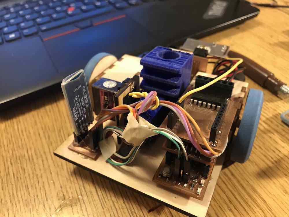
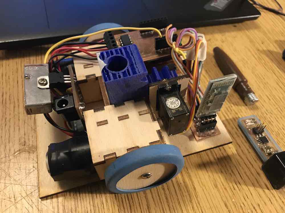
Box Turtle, a Final Project
class="pic">
The Firmware
GENERAL COMMENTS/SETUP/MACROS:
    /*
    // Tiny44_Serial_H_Bridge_Controller.c
    // Will Rudolph
    // 2/29/19
    //
    //set lfuse to 0x5E for 20 MHz Xtal **(OxDE for no clock divide fuse)
    //
    // H-BRIDGE MOTOR DRIVER (2 motors, 2 pots) (for analog x-y motion..?)
    // ALSO VERY BASIC SERIAL w/ FTDI ADAPTOR (TX/RX)
    //
    // ATTINY44 MCU
    // TI L293DNE (45A27PM) H BRIDGE (not super beefy, should look for compatible replacements)
    //
    // 4 PWM PINS TO DRIVE H BRIDGE (these are all the hardware PWM pins on the Tiny44)
    //		PB2, PA7, PA6, PA5
    // 2 ANALOG PINS FOR POTENTIOMETERS (any two pins on portA will work)
    //		PA2 & PA4
    // 1 DIGITAL PIN FOR ENABLE (any unused pin could work (could break out EN1 and EN2, currently wired together))
    //		A3
    // 2 DIGITAL PINS FOR TX/RX (Could (re)move, mainly for debug)(maybe implement bluetooth..)
    //		A0 & A1
    // 2 PINS FOR OSCILLATOR (20Mhz)
    //		PB0 & PB1
    // 1 PIN FOR RESET BUTTON (TECHNICALLY OPTIONAL, BUT WOULDN'T RECOMEND DISABLING)
    //		PB3 (active high, pull low to reset)
    //
    // based on...
    // hello.ftdi.44.echo.c
    // Neil Gershenfeld
    // 12/8/10
    //
    // SERIAL COMMUNICATION INFO //--------------------------------------------------------------
    // 115200 baud FTDI character send and receive, string send (no string receive, yet...)
    // added functions** (pr_int(42) to print integers
    // simplified printing w/ e.g.-> pr_ascii(10) pr_ascii('H') and pr_str("hello"))
    //
    //
    // (c) Massachusetts Institute of Technology 2010
    // This work may be reproduced, modified, distributed,
    // performed, and displayed for any purpose. Copyright is
    // retained and must be preserved. The work is provided
    // as is; no warranty is provided, and users accept all
    // liability.
    //
    */

    #define F_CPU 20000000UL

    #include <avr/io.h>
    #include <util/delay.h>
    #include <avr/pgmspace.h>

    #define output(directions,pin) (directions |= pin) // set port direction for output
    #define set(port,pin) (port |= pin) // set port pin
    #define clear(port,pin) (port &= (~pin)) // clear port pin
    #define pin_test(pins,pin) (pins & pin) // test for port pin
    #define bit_test(byte,bit) (byte & (1  bit)) // test for bit set
    #define bit_delay_time 8.5 // bit delay for 115200 with overhead
    #define bit_delay() _delay_us(bit_delay_time) // RS232 bit delay
    #define half_bit_delay() _delay_us(bit_delay_time/2) // RS232 half bit delay
    #define char_delay() _delay_ms(10) // char delay

    #define serial_port PORTA
    #define serial_direction DDRA
    #define serial_pins PINA
    #define serial_pin_in (1 << PA0)   //tx on ftdi chip //PA0 (old value)
    #define serial_pin_out (1 << PA1)  //rx on ftdi chip //PA1 (old value)

    #define max_buffer 25

    #define off 255 //for motor control
Functions for Basic Serial Communication
    void get_char(volatile unsigned char *pins, unsigned char pin, char *rxbyte) {
        //
        // read character into rxbyte on pins pin
        //    assumes line driver (inverts bits)
        // eg //get_char(&serial_pins, serial_pin_in, &chr); //
        //
        *rxbyte = 0;
        while (pin_test(*pins,pin))
        //
        // wait for start bit
        //
        ;
        //
        // delay to middle of first data bit
        //
        half_bit_delay();
        bit_delay();
        //
        // unrolled loop to read data bits
        //
        if pin_test(*pins,pin)
        *rxbyte |= (1 << 0);
        else
        *rxbyte |= (0 << 0);
        bit_delay();
        if pin_test(*pins,pin)
        *rxbyte |= (1 &l;t< 1);
        else
        *rxbyte |= (0 << 1);
        bit_delay();
        if pin_test(*pins,pin)
        *rxbyte |= (1 << 2);
        else
        *rxbyte |= (0 << 2);
        bit_delay();
        if pin_test(*pins,pin)
        *rxbyte |= (1 << 3);
        else
        *rxbyte |= (0 << 3);
        bit_delay();
        if pin_test(*pins,pin)
        *rxbyte |= (1 << 4);
        else
        *rxbyte |= (0 << 4);
        bit_delay();
        if pin_test(*pins,pin)
        *rxbyte |= (1 << 5);
        else
        *rxbyte |= (0 << 5);
        bit_delay();
        if pin_test(*pins,pin)
        *rxbyte |= (1 << 6);
        else
        *rxbyte |= (0 << 6);
        bit_delay();
        if pin_test(*pins,pin)
        *rxbyte |= (1 << 7);
        else
        *rxbyte |= (0 << 7);
        //
        // wait for stop bit
        //
        bit_delay();
        half_bit_delay();
    }

    void put_char(volatile unsigned char *port, unsigned char pin, char txchar) {
        //
        // send character in txchar on port pin
        //    assumes line driver (inverts bits)
        //
        // start bit
        //
        clear(*port,pin);
        bit_delay();
        //
        // unrolled loop to write data bits
        //
        if bit_test(txchar,0)
        set(*port,pin);
        else
        clear(*port,pin);
        bit_delay();
        if bit_test(txchar,1)
        set(*port,pin);
        else
        clear(*port,pin);
        bit_delay();
        if bit_test(txchar,2)
        set(*port,pin);
        else
        clear(*port,pin);
        bit_delay();
        if bit_test(txchar,3)
        set(*port,pin);
        else
        clear(*port,pin);
        bit_delay();
        if bit_test(txchar,4)
        set(*port,pin);
        else
        clear(*port,pin);
        bit_delay();
        if bit_test(txchar,5)
        set(*port,pin);
        else
        clear(*port,pin);
        bit_delay();
        if bit_test(txchar,6)
        set(*port,pin);
        else
        clear(*port,pin);
        bit_delay();
        if bit_test(txchar,7)
        set(*port,pin);
        else
        clear(*port,pin);
        bit_delay();
        //
        // stop bit
        //
        set(*port,pin);
        bit_delay();
        //
        // char delay
        //
        bit_delay();
    }

    void put_string(volatile unsigned char *port, unsigned char pin, char *str) {
        //
        // print a null-terminated string
        //
        static int index;
        index = 0;
        do {
            put_char(port, pin, str[index]);
            ++index;
        } while (str[index] != 0);
    }

    void pr_int(int n) {
        if (n < 0) {
            put_char(&serial_port, serial_pin_out, '-'); //putchar('-');
            n = -n;
        }
        if (n / 10 != 0)
        pr_int(n / 10);
        put_char(&serial_port, serial_pin_out, (n%10) + '0'); //putchar((n % 10) + '0');
    }

    void pr_ascii(char n)
    {
        put_char(&serial_port, serial_pin_out, n); //new line is 10, good one
    }

    void pr_str(char *string)
    {
        put_string(&serial_port, serial_pin_out, string);
    }
ADC Read and PWM Write Functions
    long read_ADC2() //reads ADC attached to PA5 and returns a long, 0-1023
    {
        uint16_t a,a_0;

        ADCSRA |= (1 <<ADPS0) | (1 << ADPS1) | (1 << ADPS2) | (1 << ADEN) | (1<<ADSC); //set ADC prescale to 1/128, enable, and start conversion
        ADMUX |= (1<<MUX1); //select PA3 as analog input
        ADMUX &= ~(1<<REFS0) & ~(1<<REFS1) & ~(1<<MUX0) & ~(1<<MUX2) & ~(1<<MUX3) &  ~(1<<MUX4) &  ~(1<<MUX5);  // VCC as reference, single ended input
        DIDR0 |= (1<<ADC3D); //disable digital input for PA3
        a = ADCL; //read lower byte of ADC
        a_0 = ADCH; //read upper byte of ADC (really just 2 bits)
        return a + (a_0<<8); //return lower byte plus upper 2 bits shifted 8 left (which is just the original 10-bit number)
    }

    long read_ADC4() //reads ADC attached to PA5 and returns a long, 0-1023
    {
        uint16_t a,a_0;
        ADCSRA |= (1 << ADPS0) | (1 << ADPS1) | (1 << ADPS2) | (1 << ADEN) | (1<<ADSC); //set ADC prescale to 1/128, enable, and start conversion
        ADMUX |= (1<<MUX2); //select PA5 as analog input
        ADMUX &= ~(1<<REFS0) & ~(1<<REFS1) & ~(1<<MUX0) &  ~(1<<M;UX1) & ~(1<<MUX3) &  ~(1<<MUX4) &  ~(1<<MUX5);  // VCC as reference, single ended input
        DIDR0 |= (1<<ADC5D); //disable digital input for PA5
        a = ADCL; //read lower byte of ADC
        a_0 = ADCH; //read upper byte of ADC (really just 2 bits)
        return a + (a_0<<8); //return lower byte plus upper 2 bits shifted 8 left (which is just the original 10-bit number)
    }

    long map(long x, long in_min, long in_max, long out_min, long out_max) //value map function (from Arduino)
    {
        return (x - in_min) * (out_max - out_min) / (in_max - in_min) + out_min;
    }

    void pwm_init_OC0()
    {
        //pwm init -- remember to enable DDRx for PA7 or PB2

        TCCR0A |= (1<<COM0A1) | (1<<COM0B1) |  (1<<WGM00); //;    //phase correct pwm, OC0A(PB2) and OC0B(PA7) add (1<<COM0B0) | (1<<COM0A0) to invert
        TCCR0B |= (1<<CS00); //no clock prescaling  (1<<CS01) | (1<<CS02)
        //
    }

    void pwm_init_OC1()
    {
        //pwm init -- remember to enable DDRA for PA5 and/or PA6
        TCCR1A |= (1<<COM1A1) | (1<<COM1B1) | (1<<WGM10);//phase correct pwm 8 bit
        //| (1<<COM1A0) | (1<<COM1B0)?? turn COM bits off to put pin back to normal operation
        TCCR1B |= (1<<CS10); //no clock prescaler
    }

    void pa5_pwm_write(uint8_t val)
    {
        OCR1BL = val;
    }

    void pa6_pwm_write(uint8_t val)
    {
        OCR1AL = val;
    }

    void pa7_pwm_write(uint8_t val)
    {
        OCR0B = val;
    }

    void pb2_pwm_write(uint8_t val)
    {
        OCR0A = val;
    }
Movement Functions
    void sec_delay(int sec)
    {
        while(sec--)
        {
            _delay_ms(1);
        }

    }

    void forward(uint8_t spd, float duration)
    {
        //drive motor 1 & 2 //CCW
        DDRB &= ~(1<<DDB2);		//LEFT MOTOR
        DDRA &= ~(1<<D;DA6);		//disable port that isn't driving H-Bridge
        DDRA |= (1<<DDA7);
        DDRA |= (1<<DDA5);		//enable port that is driving
        PORTA |= (1<<PA3);		//make sure enable is HIGH
        pa7_pwm_write(spd);
        pa5_pwm_write(spd-30);
        sec_delay(duration);
        pa7_pwm_write(off);
        pa5_pwm_write(off);
    }

    void backward(uint8_t spd, float duration)
    {
        DDRA &= ~(1<<DDA7);		//LEFT MOTOR
        DDRA &= ~(1<<DDA5);		//same as above but for one thing, see below
        DDRB |= (1<<DDB2);
        DDRA |= (1<<DDA6);
        PORTA |= (1<<PA3);
        pb2_pwm_write(spd);
        pa6_pwm_write(spd-30);
        sec_delay(duration);
        pb2_pwm_write(off);
        pa6_pwm_write(off);
    }

    void left(uint8_t spd, float duration)
    {
        DDRA &= ~(1<<DDA7);
        DDRA &= ~(1<<DDA6);
        DDRB |= (1<<DDB2);
        DDRA |= (1<<DDA5);
        PORTA |= (1<<PA3);
        pb2_pwm_write(spd);
        pa5_pwm_write(spd-30);
        sec_delay(duration);
        pb2_pwm_write(off);
        pa5_pwm_write(off);
    }

    void right(uint8_t spd, float duration)
    {
        DDRB &= ~(1<<DDB2);
        DDRA &= ~(1<<DDA5);
        DDRA |= (1<<DDA7);
        DDRA |= (1<<DDA6);
        PORTA |= (1<<PA3);
        pa7_pwm_write(spd);
        pa6_pwm_write(spd-30);
        sec_delay(duration);
        pa7_pwm_write(off);
        pa6_pwm_write(off);
    }

    void servo_init()
    {
        DDRA |= (1<<DDA4); //enable servo signal pin
        PORTA |= (1<<PA4); //send two pulses to set initial position
        _delay_us(1300);
        PORTA &= ~(1<<PA4);
        _delay_ms(1);
        PORTA |= (1<<PA4);
        _delay_us(1300);
        PORTA &= ~(1<<PA4);
    }

    void servo_up()
    {
        PORTA |= (1<<PA4);
        _delay_us(1300);
        PORTA &= ~(1<<PA4);
        _delay_ms(1);
        PORTA |= (1<<PA4);
        _delay_us(1300);
        PORTA &= ~(1<<PA4);

    }

    void servo_down()
    {
        PORTA |= (1<<PA4);
        _delay_us(1000);
        PORTA &= ~(1<<PA4);
        _delay_ms(1);
        PORTA |= (1<<PA4);
        _delay_us(1000);
        PORTA &= ~(1<<PA4);
    }

    void run(uint8_t f_speed, float f_dur, uint8_t t_speed, float t_dur)
    {
        char character;
        get_char(&serial_pins, serial_pin_in, &character);
        if (character == 'w')
        {
            forward(f_speed,f_dur);
        }
        else if (character == 's')
        {
            backward(f_speed,f_dur);
        }
        else if (character == 'a')
        {
            left(t_speed,t_dur);
        }
        else if (character == 'd')
        {
            right(t_speed,t_dur);
        }
        else if (character == 'p')
        {
            servo_up();
        }
        else if (character == 'l')
        {
            servo_down();
        }
        else if (character == 'x')
        {
            PORTA &= ~(1<<PA3); //disable motor driver to prevent overheating
        }

        PORTA &= ~(1<<PA3); //disable motor driver to prevent overheating
    }
The Main Function
    int main(void) { //Setup Code

	// initialize necessary variables
	uint8_t fwd_speed, turn_speed;
	int fwd_dur, turn_dur;

	// initialize output pins //output is normally pulled high (pulled low to send data)
	set(serial_port, serial_pin_out);  //same as PORTA |= (1<<PA1)
	output(serial_direction, serial_pin_out);  //same as DDRA |= (1<<PA1)

	// set PWM pins as output
	DDRA |= (1<<DDA5) | (1<<DDA6) | (1<<DDA7);
	DDRB |= (1<<DDB2);

	pwm_init_OC0(); //initialize timer/counter0 (PB2 & PA7)
	pwm_init_OC1(); //initialize timer/counter1 (PA6 & PA5)

	//Start with motors disabled
	DDRA |= (1<<DDA3);		//Set motor enable pin to output
	PORTA &= ~(1<<DDA3);	//Pull low (motors disabled)

	//Initialize Speed and Duration Variables
	//Tweak these to change movement characteristics
	fwd_dur = 10;  //now in ms//one decimal precision (change delay ms to 10 in delay function to give 2 places of precision)
	fwd_speed = 200; //(255-0, 255 off, 0 on)
	turn_dur = 10;
	turn_speed = 200;

	//Initialize Servo
	servo_init();
	servo_up();

	while (1) { //Looping Function

		// w, a, s, d used for fwd, left, back, right respectively
		run(fwd_speed,fwd_dur,turn_speed,turn_dur);
	   }
    }
Interface Code
The Processing Application Code
    /**
     * Keyboard Turtle Control
     *
    **/

    import processing.serial.*;

    Serial myPort;  // Create object from Serial class
    int val;        // Data received from the serial port

    void setup()
    {
      size(500, 500);
      // I know that the first port in the serial list on my mac
      // is always my  FTDI adaptor, so I open Serial.list()[0].
      // On Windows machines, this generally opens COM1.
      // Open whatever port is the one you're using.
      String portName = "COM26";
      myPort = new Serial(this, portName, 115200);
    }

    void draw() {
      // keep draw() here to continue looping while waiting for keys
    }

    void keyPressed() {
      if (key == 'w') {
        myPort.write('w');
      }
      else if (key == 'a') {
        myPort.write('a');
      }
      else if (key == 'd') {
        myPort.write('d');
      }
      else if (key == 's') {
        myPort.write('s');
      }
      else{
        myPort.write('x');
      }
    }
Powershell Script to Send a Controlled Character Stream
    PS C: $turt = New-Object System.IO.Ports.SerialPort COM35, 115200, None, 8, one
    PS C: $turt.open()
    PS C: Get-Content C:\Users\will.rudolph\Documents\txt_files\txt_test.txt -Encoding Byte | foreach { $turt.write([char]$_); Start-Sleep -Milliseconds 5 }
Python Program to Generate Character Stream
    char_list = []

    def fwd(len):
        for i in range(10*len):
            char_list.append('s')

    def rev(len):
        for i in range(10*len):
            char_list.append('w')

    def left(len):
        for i in range(10*len):
            char_list.append('a')

    def right(len):
        for i in range(10*len):
            char_list.append('d')

    def triangle():
        fwd(3)
        right(100)
        fwd(3)
        right(100)
        fwd(3)

    for i in range(5):
        triangle()
        right(60)

    print(''.join(char_list))
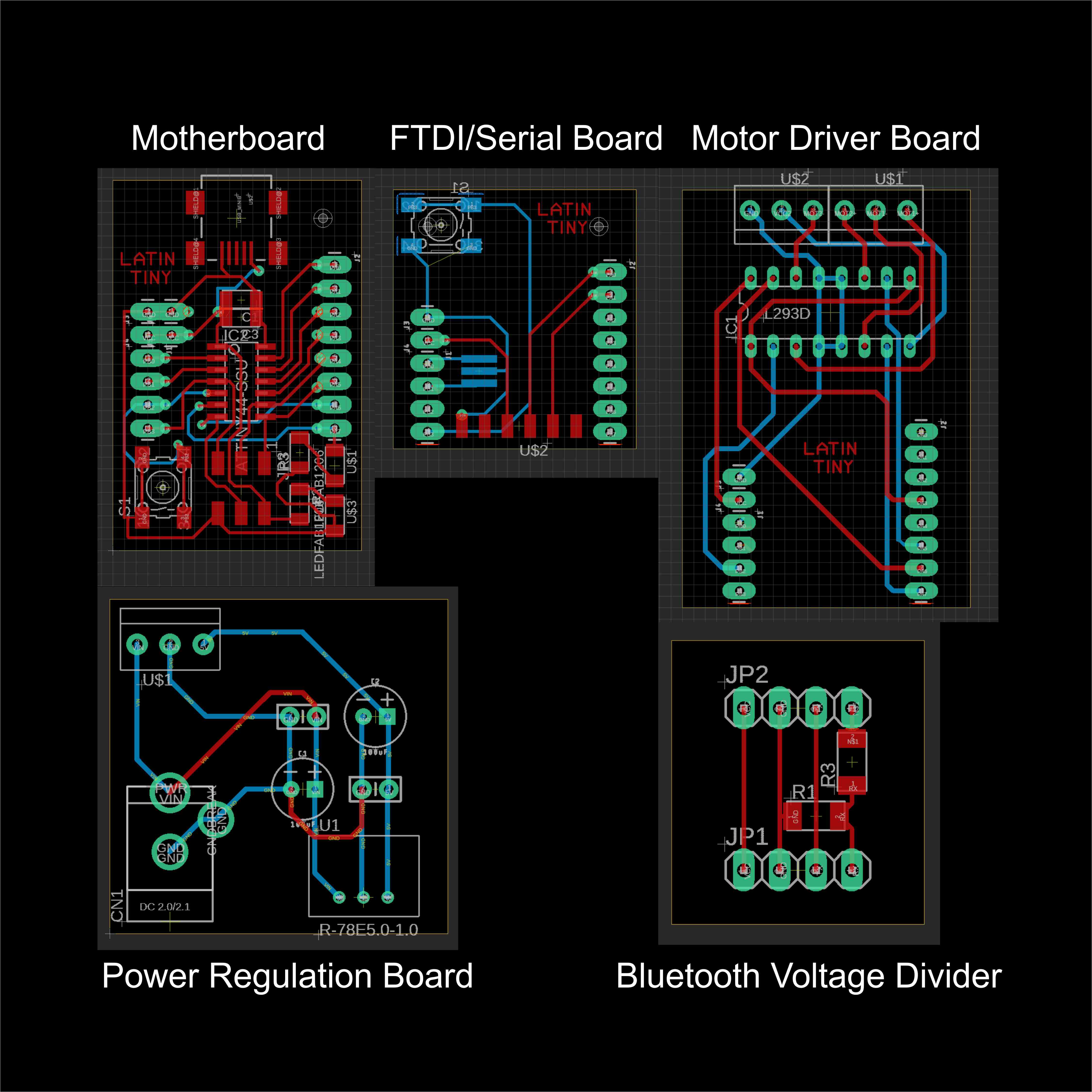
Circuit Board Designs
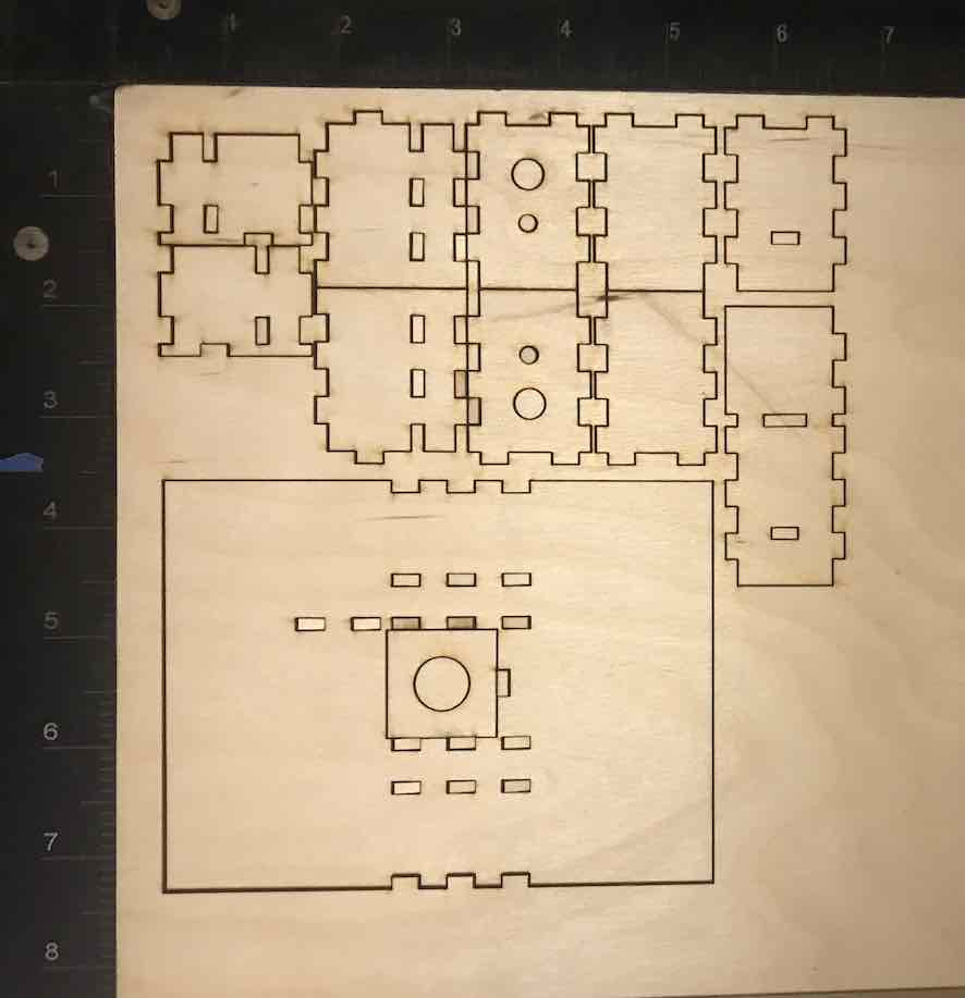
Chassis Design