
IMPLEMENTATION
Once the sensors have been calibrated, detailed the logic of programming and testing of all the instruments, it is time to start assembling the final project.
The first step is to place the tank already lined inside its structure to be able to locate the orientation of the sensor and, most importantly, calculate the amount of cables and lengths needed to connect the sensors with the controller
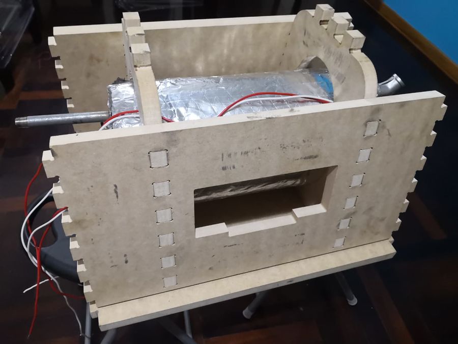 The tank will be subjected to pressure due to the design and the lining of the tank. In addition it will not move through the pipes of the tank itself, as shown in the picture.
 I decided that all the control electronics will be on the outlet side of the steam and only the relay will be at the water inlet, so all the water level cables will go through the steam outlet.
I connect the pressure and temperature sensors in their corresponding places: the pressure sensor on the right and the temperature sensor, which goes from the left of the tank, we incorporate their electronics in the upper part of the tank, and this goes to the controller
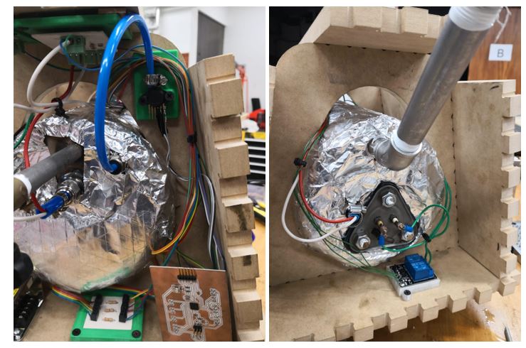 So, it seems that it was a small bomb, but we should not be alarmed because it is necessary to fit the cables well to make it more esthetic.
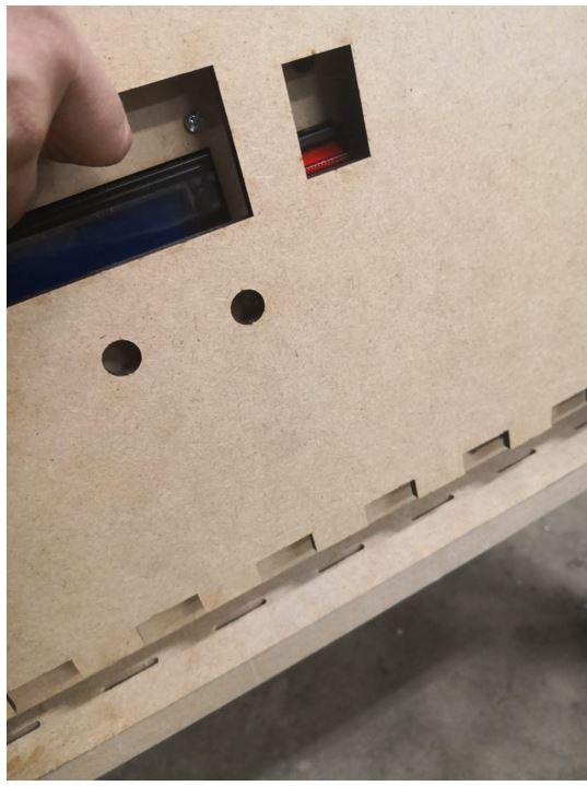
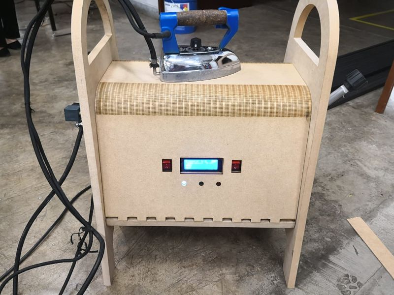
The user interface, which is composed of the screen, the 3 LEDs and the turn on switches of the iron and the resistance will be in the structure and the necessary cables will be passed.
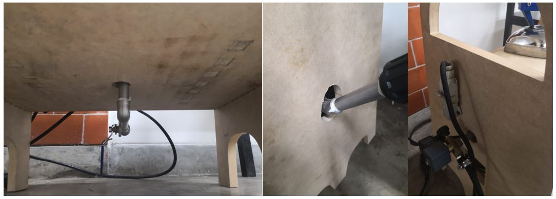
The data cables will go through the top of the tank while the alternating current cables will go under the tank and will follow in parallel to the data cables.
WE DO NOT HAVE TO MIX DATA CABLES WITH POWER CORDS. The resistance relay and the corresponding wiring to the resistance are incorporated.
Once all the sensors, the LEDs and the screen are connected to the controller and the power supply, we start to see if everything works correctly.
The first tests are performed to find possible wiring and code failures. After some small adjustments of the wiring and new welding of some points, we can see that the programmed logic works correctly.
Here is a small video.
Finally is time to put the flex pattern. In the design of the base there are some small tabs in which the design will fit, as shown in the image. The design as such is an offset of the assembly with the sheet metal tool.
 Here is my beatiful project.
 Return to final project