Week seventeen: Machine Design
For this week's assignment I will tell you my personal contribution
CNC board
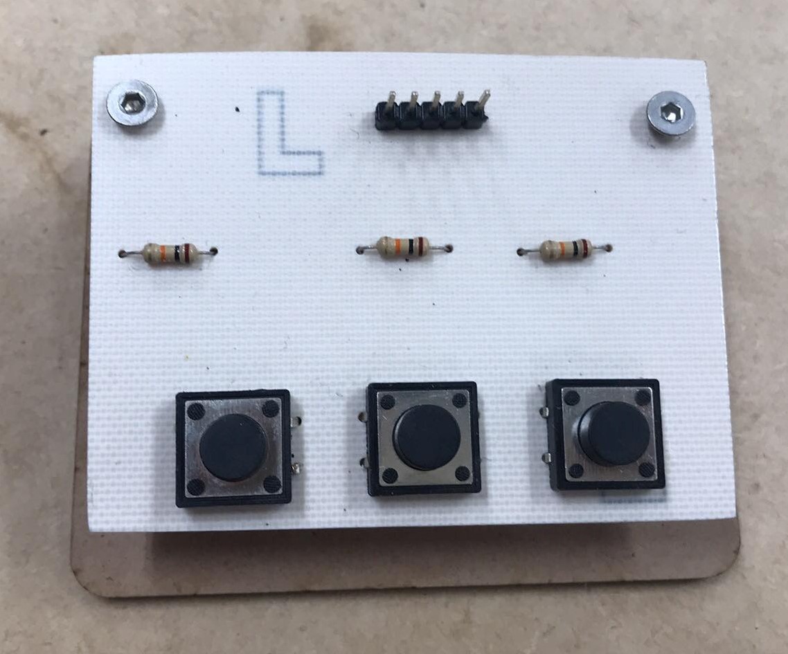
This week I decided to design and manufacture a true hole plate to turn on, turn off and pause the CNC that we are putting together.
I designed the plate in Eagle, I added 3 buttons and 3 resistors, 5 pins of which 3 are for signal buttons and the other 2 GND and VCC respectively, the configuration of the buttons depend on the direction in which the power pins are connected , for example if VCC is connected through the VCC pin it will be a pull down configuration, if VCC is connected to the GND pin and GND to the VCC pin it will have a pull up configuration, for our case it is desirable to work with pull down


Cabling
Since they told us that it would be optimal if the electronics were outside the CNC, we bought a cable to connect the motors to the drivers, with a 24 AWG gauge

With the help of this cable stripper, I removed the lining of the internal cables and put terminals on the tips, in order to maintain more order


Then I passed the cables through these fasteners, which will move according to the movement of the CNC

And I screwed the structures that I designed and designed for the cable fixer

I also set some limit switches, which will detect when the machine is at the limit

The cables of the limit switches will also pass through the cable fixers

The result was the following

To see the complete development of the CNC machine visit the following link that corresponds to the CIT page