Final Project - Conveyor System
Video
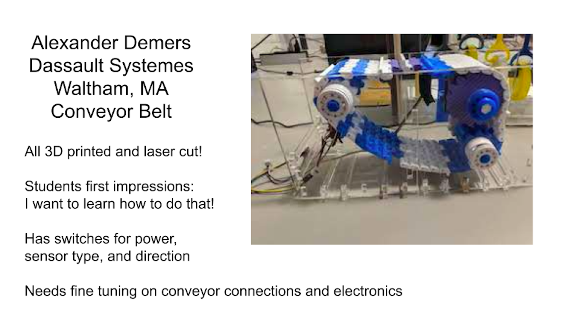
Slide
Overview
Over the course of my time in Fab Academy, my final project pivoted a couple times. At first I wanted to make an extruder to recycle failed or obsolete 3D prints, then a wireless fan and thermometer for my smoker, before settling on a modular conveyor system to showcase the capabilities of digital fabrication in a fun way to the students I teach.
Taking inspiration from the belt system I developed during machine design, I decided it had everything in it to satisfy the requirements of a final project (thus my applications and implications week being…not for this). So let’s get to it!
Design
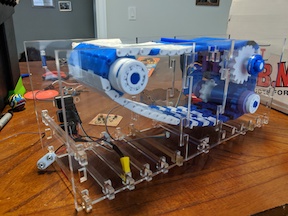
Inspired by my (original conveyor design](http://fabacademy.org/2019/labs/dassault/students/alexander-demers/assignments/week15/), I decided to change a couple things. First off, move away from the pin system to a snap, which increases the flexibility of it. I was able to keep the same footprint on the underside for the sprockets to catch, so that was a plus! I also wanted to hide the motor within the conveyor belt, so it was important to make them a bit wider so that the motor could be tucked away.
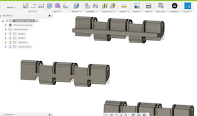
The three images there are the original snap ones I made. I also included ones with the wall for working on an incline. The third one I made when I realized that the original design was flimsy and prone to breaking. I made the top surface higher, which greatly improved the resiliency of the pieces. It did slightly decrease the flexibility, but it was still better than the pin junction.
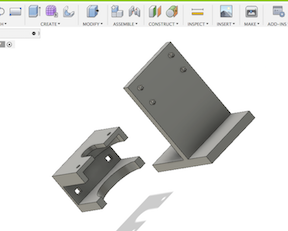
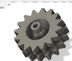
Since the shape was the same, the sprockets could be re-used. However, since the motor would be inside the system, the main sprocket to drive the system needed to be big enough to hide the motor, shown below. I also need to make a little platform for the motor to rest on. I liked the design of the frame for the smaller system, so I re-made that to meet the bigger size and put in a slit for the motor platform to go through. The offsets on it would allow to press against the side and remain stable.
So rran everything off and checked it out. First thing I noticed was I misjudged the radius I needed for the sprocket, and the links were rubbing against the motor holder. So I adjusted the body to put in another set of sprockets underneath to ensure clearance.
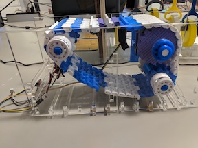
Now that the mechanical pieces have been made, it was time to see how it worked!
Great! Unfortunately, things would occassionally slip.
From there, I decided to redo that sprocket. Instead of being only in contact with one part of each link, two would provide more stability. So I used the measurements from my conveyor link file and redid the sprocket. I also redid the edges to not be rounded.
I also adjusted the size of the spacers and included a guide lip on the sprocket assembly below the drive sprocket to attempt to better keep things in line.
For each segment of the middle you add, it takes an additional 10 belt link pieces to satisfy it.
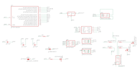
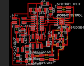
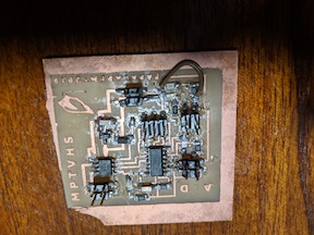
Electronics
The board I used here is one that was used on my input and output devices. I used the programming from the board on the old conveyor as a starting point. I did add a few items, however. I included a switch to change the direction that the board goes, as well as one to turn on and off the distance/motion sensor.

Code
I used a modified code from the previous version, and included the switches using if statements to control the direction of the flow and how it runs. Unfortunately the motion sensor/always on switch doesn’t work yet, but that can something I will continue to work on! I did initially have a problem trying to use a digital read for the direction switch, but changed it to an analog and it worked like a charm! The code below shows a digital for the run method switch, but I also have tried that as an analog to no success yet.
int in1 = 3;
int in2 = 2;

int revswitch = 7;
int onswitch = 8;
int reverse;
int always;

void setup() {
  // put your setup code here, to run once:
  pinMode(in1, OUTPUT);
  pinMode(in2, OUTPUT);
  pinMode(revswitch, INPUT);
  pinMode(onswitch, INPUT);

  // make sure motor is off
  digitalWrite(in1, LOW);
  digitalWrite(in2, LOW);

  delay (500);
}

void loop() {
  // put your main code here, to run repeatedly:

reverse = analogRead(revswitch);
always = digitalRead(onswitch);

delay (500);

analogWrite(in1 , 0);
analogWrite(in2 , 0);


if (always = HIGH) {
  if (reverse < 700) {
    analogWrite(in1, 128);
    analogWrite(in2, 0);
  } else {
    analogWrite(in1 , 0);
    analogWrite( in2 , 128);
  }
 } else {
  analogWrite(in1 , 0);
  analogWrite(in2 , 0);
 }

}
This version doesn’t have the motion sensor controls in there given the issues getting that switch to work. However, they are on the same pins as in my previous model, so it would be easy enough to incorporate that code.
Video
It works! Kind of. The motor seems to be running really fast - a slower speed would probably not slip as much. Unfortunately the motor’s internal resistance would not allow it to run at less than 8 V, which is what we saw here. But the directions work, the belt holds together, and it can run smoothly when it does not slip!
Bill of Materials
| Item | Quantity | Cost | Total | Link |
|---|---|---|---|---|
| 3D Printer Filament | 2 Spools | $19.99 | $39.98 | Amazon |
| Acrylic | 2 Sheets 12x24 | $7.60 | $15.20 | J Freeman |
| ATTiny44 | 1 | $1.18 | $1.18 | Digikey |
| Various other Electronic components | Variable | ~ $10 | ~$10 | Digikey |
| Motor | 1 | $12.95 | $12.95 | Jameco |
| Motion Sensor | 1 | $1.76 | $1.76 | Amazon |
| Total: | $81.07 |
Not too bad, for pricing! It also is way more filament and acrylic than is needed. Wood could also be substituted, which would further reduce the cost.
Skills Used
The skills used in this are as follows: - 2-D Design (the framing) - 3-D Design (the components to the conveyor system) - Electronics Design and programming (the circuitry and programming of the microcontroller) - Additive manufacturing (all components of the conveyor were 3-D printed) - Subtractive manufacturing (the framing is laser cut acrylic) - Input devices (switches, motion sensor) - Output devices (motor, LEDs)
Previous Weeks
The following weeks were directly used in the making of this project:
Next Steps
Moving forward, I would like to fix the sprocket so that it does not skip, as well as slow down the motor speed. I did try to use a 9 V battery with the system, but unfortunately it does not put out enough voltage due to the internal resistance, so finding a good battery system would be great. I would also like to further work to compress the electronics into the system. Also, work on the firmness of the connections between adjacent frame pieces, so I can get rid of the chip clips.
Design Files
Shoutouts
Thanks to Luciano and Greg for helping out during this hectic class!
Thank you to everyone at Madison Park Technical Vocational High School for supporting me and being understanding while I took this class.
And most importantly, thanks to my wife Savannah and our beautiful dogs!