14. Networking and Communications - Bus Style
This week I would like to focus on stylizing the board design, as a first attempt to consider how my final project board designs will work. I’m thinking shearing the boards, and using the rigid orthogonal constraints of the components as design opportunities.
Assignment individual assignment: design, build, and connect wired or wireless node(s) with network or bus addresses group assignment: send a message between two projects
I’ll do the asynchronous bus variety, using Neil’s bus setup as inspiration for my design.
Board Design Idea
My first step is to consider Neil’s designs and how I’ll modify it, to make it my own. Perhaps shearing it, like a parallelogram?
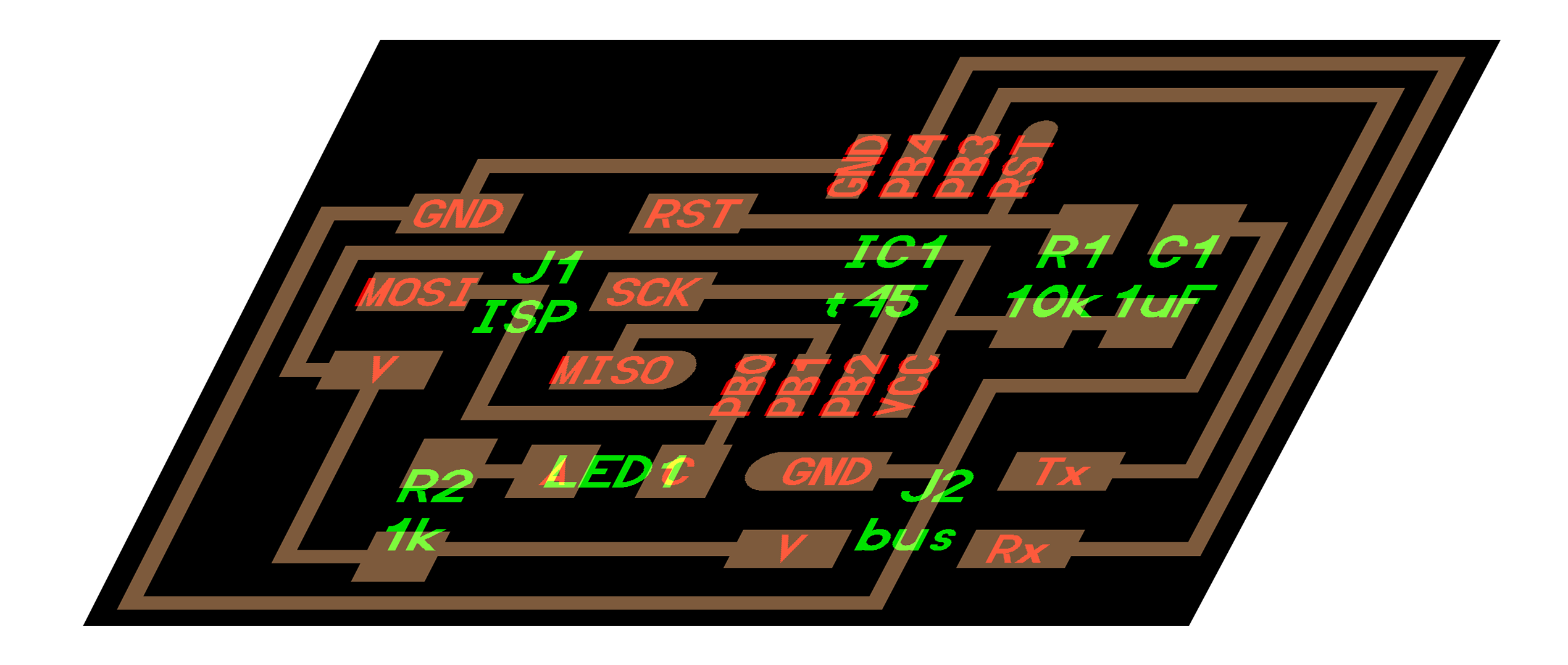
Sheared node board:
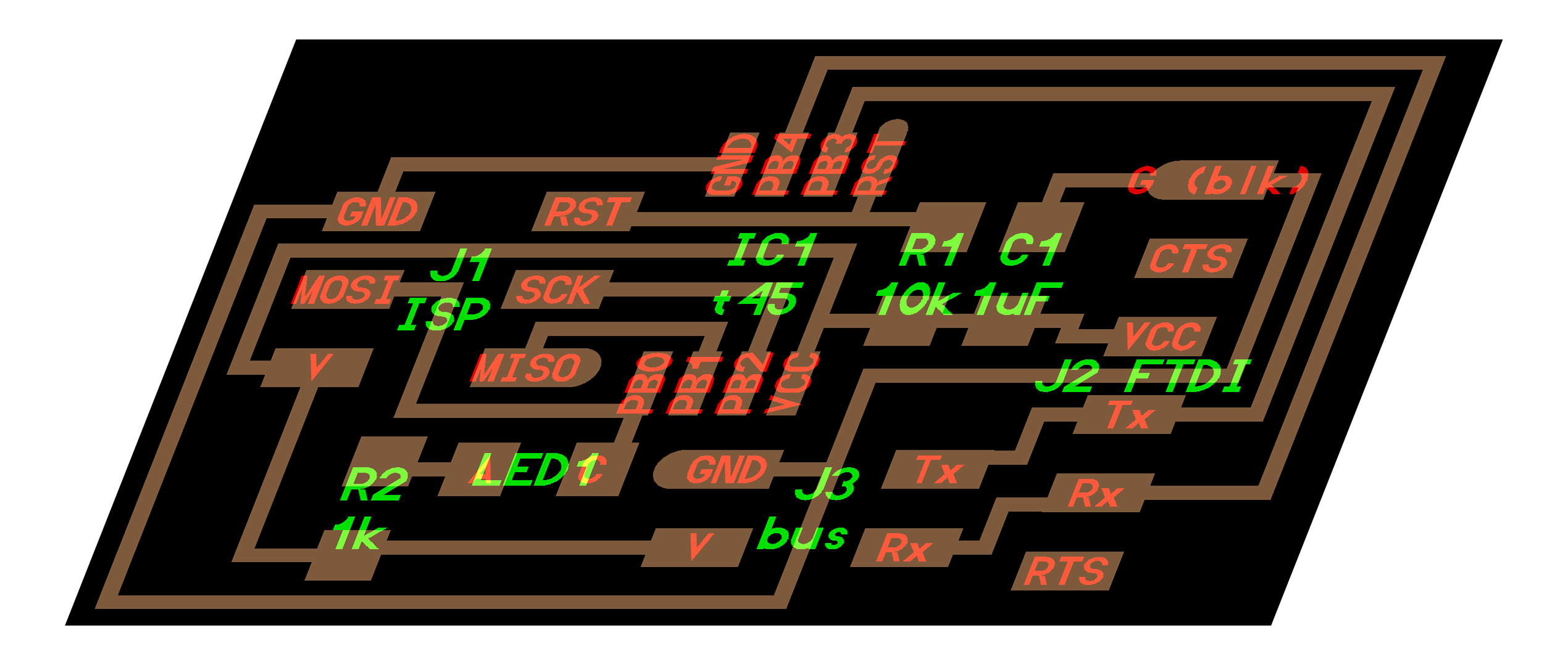
Sheared bridge board:
Gather Components
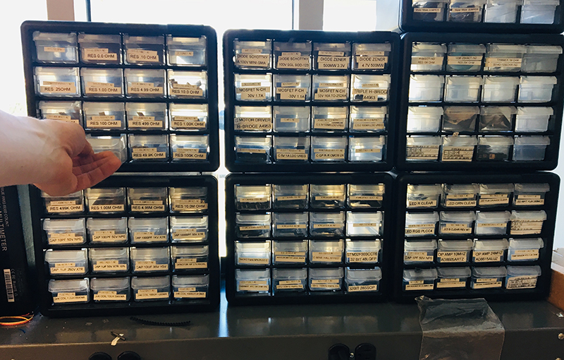 I will say after 10+ weeks, the electronics bench is finally getting easier to navigate!
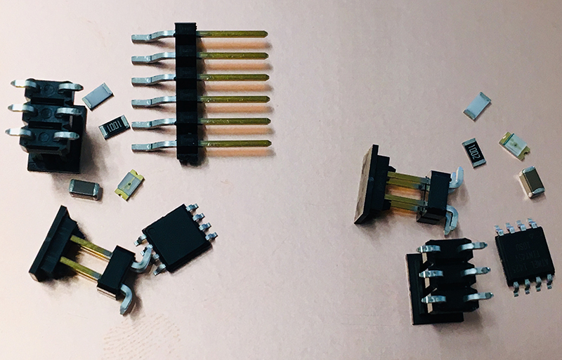
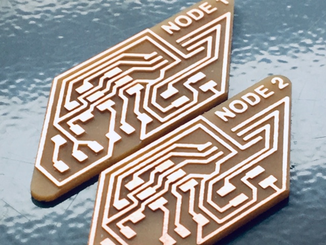
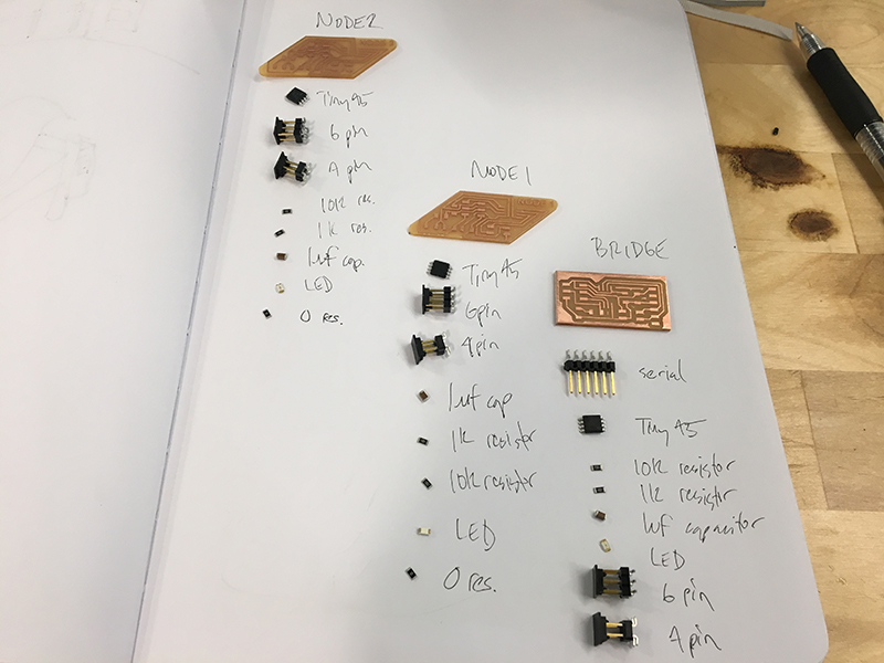
Node Board X 2
1k resistor 10k resistor 1uF capacitor 4 pin header (bus) 6 pin header (ISP) AtTiny45 Microprocessor LED
Bridge Board
1k resistor 10k resistor 1uF capacitor 4 pin header (bus) 6 pin header (ISP) 6 pin serial FTDI AtTiny45 Microprocessor LED
EAGLE Design Work
Next, on to EAGLE to design the layout of the two different boards. I’m excited to consider the artistic side of board layout and design.
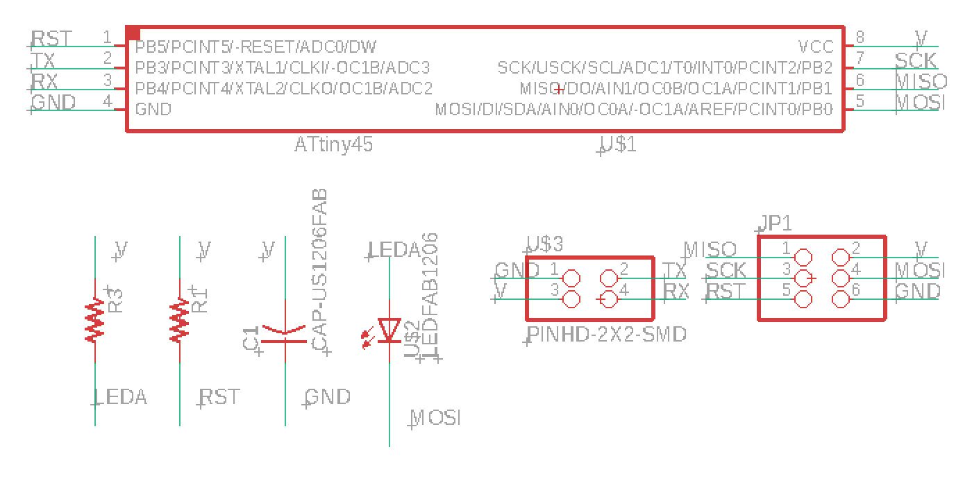
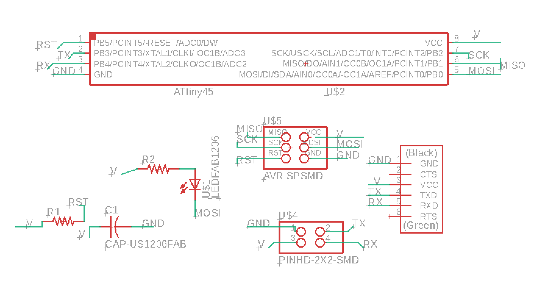
Node Schematic - downloadable file
I use the Nets technique, naming the connections to establish the links:
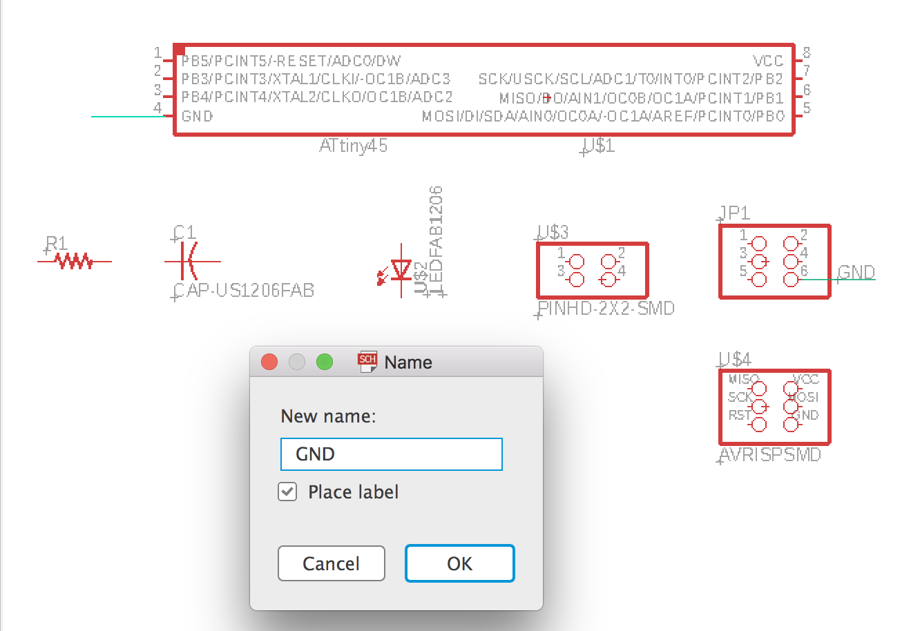
Final schematic:
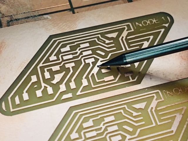
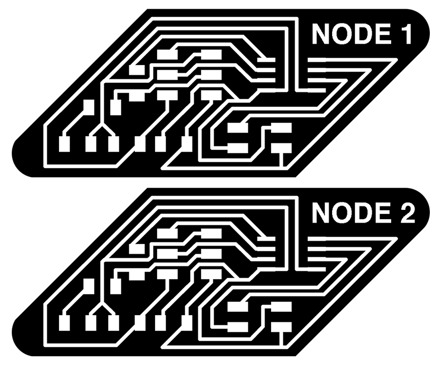
Node Board - downloadable file
For this one, I’m trying not to use Neil’s layout, instead, just getting a feel for starting from scratch trying to get a feel for how the components best fit together.
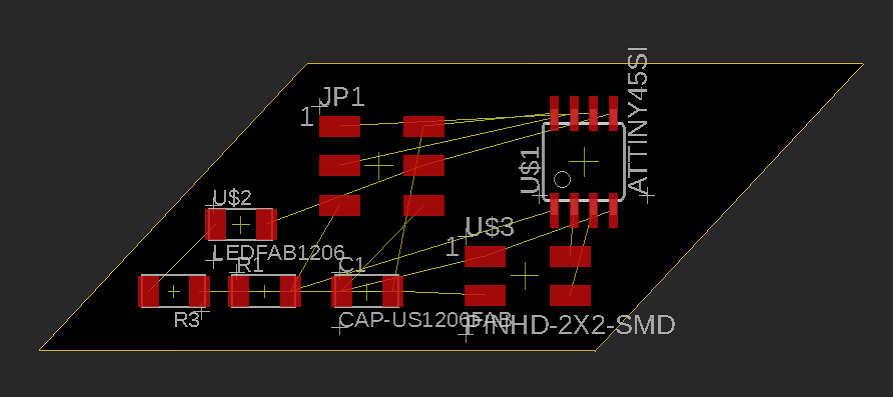
So far so good…just a couple dead-ends and/or blocking components from getting attached.
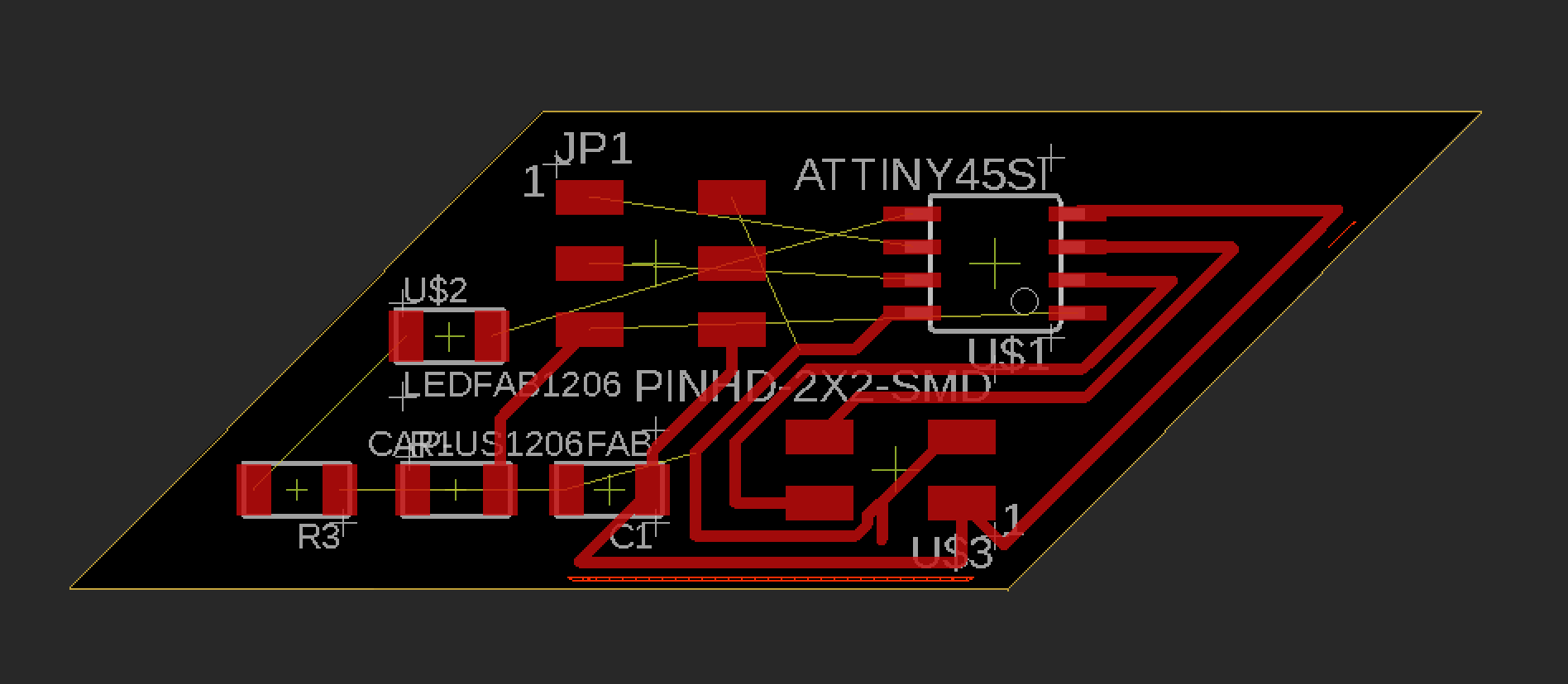
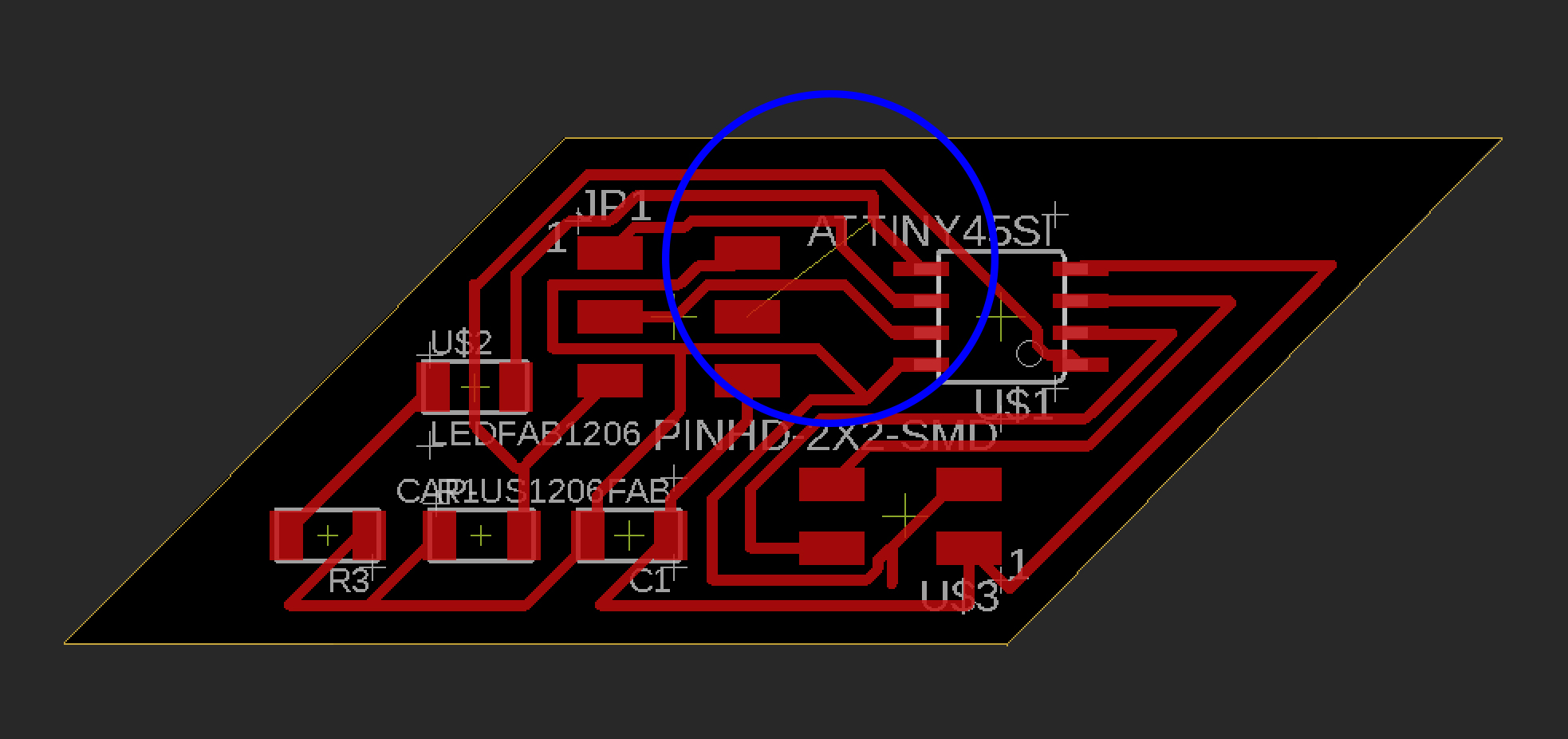 So…I really trapped myself with this layout. I’ve tried to delete and re-wire it, but no go. My solution will be to add 0 ohm resistor to jump over the line.
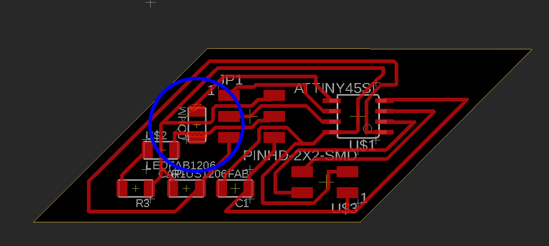 Here’s my added 0 ohm resistor. I think this will work. I simply went back to the schematic and added a resistor, labeled it 0 ohm, then went back to the board design and arranged it on top of the line end points. It will now throw an error when I run DRC, but I can live with that.
HOpefully the Bridge design will go smoother.
Here’s my final board design:

Here’s the MODs set up:
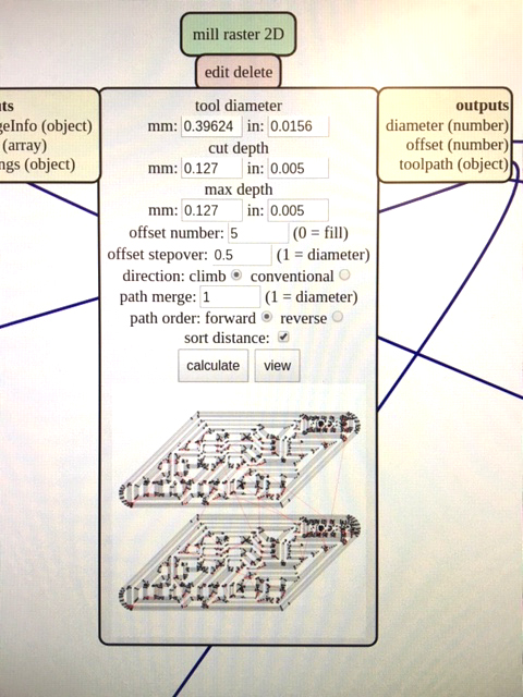 I’ve been changing the offset to 5 and the cut depth/max cut depth to .005 (it’s set to .004 by default, but I’ve found that doesn’t cut deep enough across the whole board)
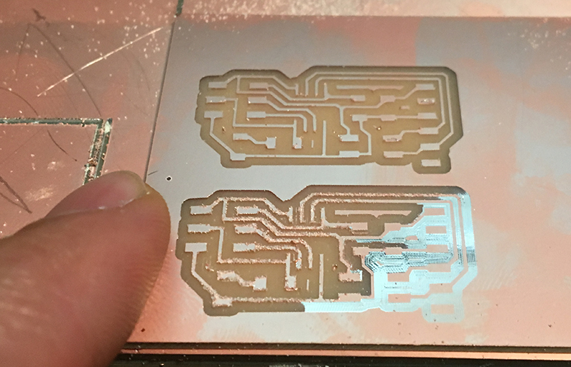
FAIL :(
This board didn’t fully cut out all the paths…so I will go back to the Eagle file and modify the routing. What’s strange is that the DRC didn’t call out these potential errors. What a pain!
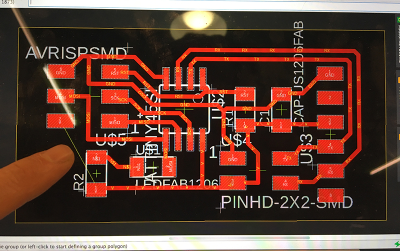
Here’s the revised board design - I made the spacing between the routes larger, and smoothed out some of the kinks, as well as made the text bigger!
Bridge Schematic - downloadable file
 The schematic is pretty straightforward.
Bridge Board - downloadable file
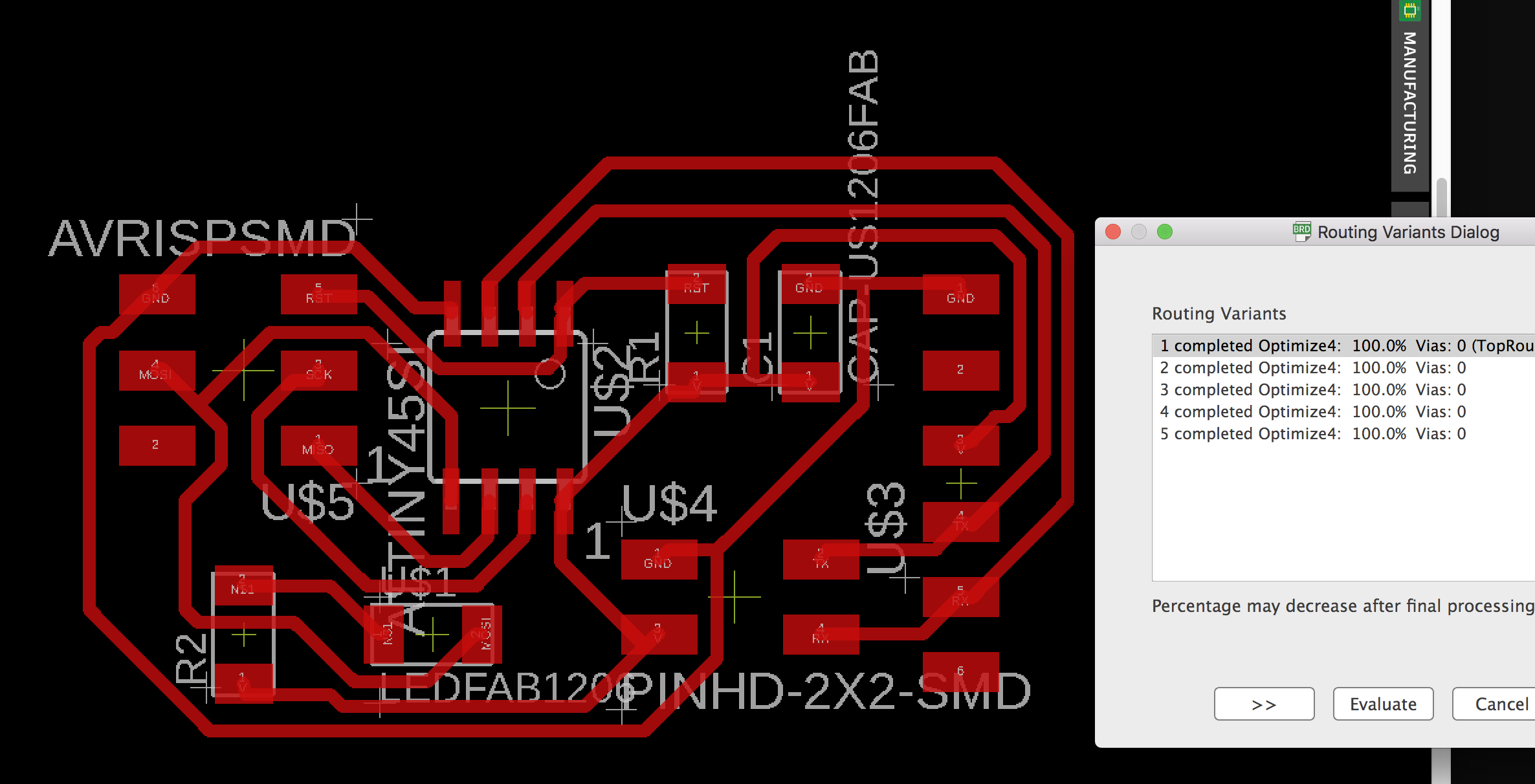 I used autoroute again after using ratsnest to get arrangement cleaned up. It worked 100% on first try! I did end up making some minor adjustments again before autorouting.
Oops!
Looks like one of my connections in the schematic wasn’t fully connected, so I was missing a route in the board. I caught while preparing the MODS setup. Good thing I was double checking stuff!
 Here’s where I noticed a seemingly missing connection.
 I went back into the schematic, remade the connection and then manually routed it into the board design.
It seems the bit stopped cutting half way through. I’m not sure exactly why.
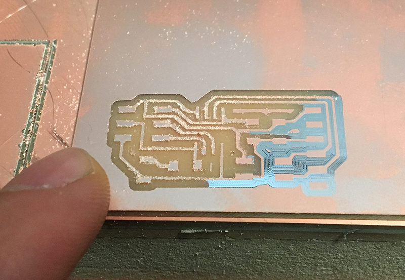
Milled
I changed the tool with a new one and sent the file to another part of the board. Seems like that fixed it:
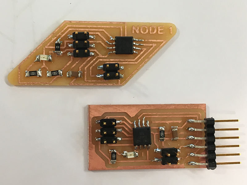
Soldering
Here are the bridge and node board components, ready to solder!
Programming
I will use the Arduino workflow instead of using the terminal on my virtual Unbunto computer.
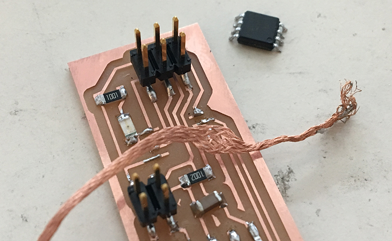
The bridge board wouldn’t bootload so I decided to resolder the Tiny45 - a couple times - in order for it to read properly. It did finally work!
I successfully bootloaded each board and uploaded Neil’s C code:
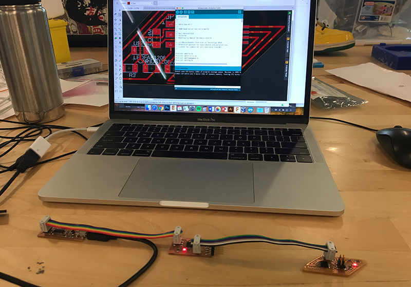
Here’s Neil’s original C code. I first uploaded this to my bridge board via Arduino.
//
//
// hello.bus.45.c
//
// 9600 baud serial bus hello-world
//
// Neil Gershenfeld
// 11/24/10
// Modified by Daniel Smithwick 6/6/19

// (c) Massachusetts Institute of Technology 2010
// Permission granted for experimental and personal use;
// license for commercial sale available from MIT.
//

#include <avr/io.h>
#include <util/delay.h>
#include <avr/pgmspace.h>
#include <string.h>

#define output(directions,pin) (directions |= pin) // set port direction for output
#define input(directions,pin) (directions &= (~pin)) // set port direction for input
#define set(port,pin) (port |= pin) // set port pin
#define clear(port,pin) (port &= (~pin)) // clear port pin
#define pin_test(pins,pin) (pins & pin) // test for port pin
#define bit_test(byte,bit) (byte & (1 << bit)) // test for bit set
#define bit_delay_time 100 // bit delay for 9600 with overhead
#define bit_delay() _delay_us(bit_delay_time) // RS232 bit delay
#define half_bit_delay() _delay_us(bit_delay_time/2) // RS232 half bit delay
#define led_delay() _delay_ms(100) // LED flash delay

#define led_port PORTB
#define led_direction DDRB
#define led_pin (1 << PB0)

#define serial_port PORTB
#define serial_direction DDRB
#define serial_pins PINB
#define serial_pin_in (1 << PB3)
#define serial_pin_out (1 << PB4)

#define node_id '0'

void get_char(volatile unsigned char *pins, unsigned char pin, char *rxbyte) {
   //
   // read character into rxbyte on pins pin
   //    assumes line driver (inverts bits)
   //
   *rxbyte = 0;
   while (pin_test(*pins,pin))
      //
      // wait for start bit
      //
      ;
   //
   // delay to middle of first data bit
   //
   half_bit_delay();
   bit_delay();
   //
   // unrolled loop to read data bits
   //
   if pin_test(*pins,pin)
      *rxbyte |= (1 << 0);
   else
      *rxbyte |= (0 << 0);
   bit_delay();
   if pin_test(*pins,pin)
      *rxbyte |= (1 << 1);
   else
      *rxbyte |= (0 << 1);
   bit_delay();
   if pin_test(*pins,pin)
      *rxbyte |= (1 << 2);
   else
      *rxbyte |= (0 << 2);
   bit_delay();
   if pin_test(*pins,pin)
      *rxbyte |= (1 << 3);
   else
      *rxbyte |= (0 << 3);
   bit_delay();
   if pin_test(*pins,pin)
      *rxbyte |= (1 << 4);
   else
      *rxbyte |= (0 << 4);
   bit_delay();
   if pin_test(*pins,pin)
      *rxbyte |= (1 << 5);
   else
      *rxbyte |= (0 << 5);
   bit_delay();
   if pin_test(*pins,pin)
      *rxbyte |= (1 << 6);
   else
      *rxbyte |= (0 << 6);
   bit_delay();
   if pin_test(*pins,pin)
      *rxbyte |= (1 << 7);
   else
      *rxbyte |= (0 << 7);
   //
   // wait for stop bit
   //
   bit_delay();
   half_bit_delay();
   }

void put_char(volatile unsigned char *port, unsigned char pin, char txchar) {
   //
   // send character in txchar on port pin
   //    assumes line driver (inverts bits)
   //
   // start bit
   //
   clear(*port,pin);
   bit_delay();
   //
   // unrolled loop to write data bits
   //
   if bit_test(txchar,0)
      set(*port,pin);
   else
      clear(*port,pin);
   bit_delay();
   if bit_test(txchar,1)
      set(*port,pin);
   else
      clear(*port,pin);
   bit_delay();
   if bit_test(txchar,2)
      set(*port,pin);
   else
      clear(*port,pin);
   bit_delay();
   if bit_test(txchar,3)
      set(*port,pin);
   else
      clear(*port,pin);
   bit_delay();
   if bit_test(txchar,4)
      set(*port,pin);
   else
      clear(*port,pin);
   bit_delay();
   if bit_test(txchar,5)
      set(*port,pin);
   else
      clear(*port,pin);
   bit_delay();
   if bit_test(txchar,6)
      set(*port,pin);
   else
      clear(*port,pin);
   bit_delay();
   if bit_test(txchar,7)
      set(*port,pin);
   else
      clear(*port,pin);
   bit_delay();
   //
   // stop bit
   //
   set(*port,pin);
   bit_delay();
   //
   // char delay
   //
   bit_delay();
   }

void put_string(volatile unsigned char *port, unsigned char pin, PGM_P str) {
   //
   // send character in txchar on port pin
   //    assumes line driver (inverts bits)
   //
   static char chr;
   static int index;
   index = 0;
   do {
      chr = pgm_read_byte(&(str[index]));
      put_char(&serial_port, serial_pin_out, chr);
      ++index;
      } while (chr != 0);
   }

void flash() {
   //
   // LED flash delay
   //
   clear(led_port, led_pin);
   led_delay();
   set(led_port, led_pin);
   }

int main(void) {
   //
   // main
   //
   static char chr;
   //
   // set clock divider to /1
   //
   CLKPR = (1 << CLKPCE);
   CLKPR = (0 << CLKPS3) | (0 << CLKPS2) | (0 << CLKPS1) | (0 << CLKPS0);
   //
   // initialize output pins
   //
   set(serial_port, serial_pin_out);
   input(serial_direction, serial_pin_out);
   set(led_port, led_pin);
   output(led_direction, led_pin);
   //
   // main loop
   //
   while (1) {
      get_char(&serial_pins, serial_pin_in, &chr);
      flash();
      if (chr == node_id) {
         output(serial_direction, serial_pin_out);
         static const char message[] PROGMEM = "node ";
         put_string(&serial_port, serial_pin_out, (PGM_P) message);
         put_char(&serial_port, serial_pin_out, chr);
         put_char(&serial_port, serial_pin_out, 10); // new line
         led_delay();
         flash();
         input(serial_direction, serial_pin_out);
         }
      }
   }
I then modified the code above for the Node1 board, again via Arduino. The change being: #define node_id ‘1’ instead of ‘0’.
//
//
// hello.bus.45.c
//
// 9600 baud serial bus hello-world
//
// Neil Gershenfeld
// 11/24/10
// Modified by Daniel Smithwick 6/6/19

// (c) Massachusetts Institute of Technology 2010
// Permission granted for experimental and personal use;
// license for commercial sale available from MIT.
//

#include <avr/io.h>
#include <util/delay.h>
#include <avr/pgmspace.h>
#include <string.h>

#define output(directions,pin) (directions |= pin) // set port direction for output
#define input(directions,pin) (directions &= (~pin)) // set port direction for input
#define set(port,pin) (port |= pin) // set port pin
#define clear(port,pin) (port &= (~pin)) // clear port pin
#define pin_test(pins,pin) (pins & pin) // test for port pin
#define bit_test(byte,bit) (byte & (1 << bit)) // test for bit set
#define bit_delay_time 100 // bit delay for 9600 with overhead
#define bit_delay() _delay_us(bit_delay_time) // RS232 bit delay
#define half_bit_delay() _delay_us(bit_delay_time/2) // RS232 half bit delay
#define led_delay() _delay_ms(1000) // LED flash delay

#define led_port PORTB
#define led_direction DDRB
#define led_pin (1 << PB0)

#define serial_port PORTB
#define serial_direction DDRB
#define serial_pins PINB
#define serial_pin_in (1 << PB3)
#define serial_pin_out (1 << PB4)

#define node_id '1' //change for each additional node board

void get_char(volatile unsigned char *pins, unsigned char pin, char *rxbyte) {
   //
   // read character into rxbyte on pins pin
   //    assumes line driver (inverts bits)
   //
   *rxbyte = 0;
   while (pin_test(*pins,pin))
      //
      // wait for start bit
      //
      ;
   //
   // delay to middle of first data bit
   //
   half_bit_delay();
   bit_delay();
   //
   // unrolled loop to read data bits
   //
   if pin_test(*pins,pin)
      *rxbyte |= (1 << 0);
   else
      *rxbyte |= (0 << 0);
   bit_delay();
   if pin_test(*pins,pin)
      *rxbyte |= (1 << 1);
   else
      *rxbyte |= (0 << 1);
   bit_delay();
   if pin_test(*pins,pin)
      *rxbyte |= (1 << 2);
   else
      *rxbyte |= (0 << 2);
   bit_delay();
   if pin_test(*pins,pin)
      *rxbyte |= (1 << 3);
   else
      *rxbyte |= (0 << 3);
   bit_delay();
   if pin_test(*pins,pin)
      *rxbyte |= (1 << 4);
   else
      *rxbyte |= (0 << 4);
   bit_delay();
   if pin_test(*pins,pin)
      *rxbyte |= (1 << 5);
   else
      *rxbyte |= (0 << 5);
   bit_delay();
   if pin_test(*pins,pin)
      *rxbyte |= (1 << 6);
   else
      *rxbyte |= (0 << 6);
   bit_delay();
   if pin_test(*pins,pin)
      *rxbyte |= (1 << 7);
   else
      *rxbyte |= (0 << 7);
   //
   // wait for stop bit
   //
   bit_delay();
   half_bit_delay();
   }

void put_char(volatile unsigned char *port, unsigned char pin, char txchar) {
   //
   // send character in txchar on port pin
   //    assumes line driver (inverts bits)
   //
   // start bit
   //
   clear(*port,pin);
   bit_delay();
   //
   // unrolled loop to write data bits
   //
   if bit_test(txchar,0)
      set(*port,pin);
   else
      clear(*port,pin);
   bit_delay();
   if bit_test(txchar,1)
      set(*port,pin);
   else
      clear(*port,pin);
   bit_delay();
   if bit_test(txchar,2)
      set(*port,pin);
   else
      clear(*port,pin);
   bit_delay();
   if bit_test(txchar,3)
      set(*port,pin);
   else
      clear(*port,pin);
   bit_delay();
   if bit_test(txchar,4)
      set(*port,pin);
   else
      clear(*port,pin);
   bit_delay();
   if bit_test(txchar,5)
      set(*port,pin);
   else
      clear(*port,pin);
   bit_delay();
   if bit_test(txchar,6)
      set(*port,pin);
   else
      clear(*port,pin);
   bit_delay();
   if bit_test(txchar,7)
      set(*port,pin);
   else
      clear(*port,pin);
   bit_delay();
   //
   // stop bit
   //
   set(*port,pin);
   bit_delay();
   //
   // char delay
   //
   bit_delay();
   }

void put_string(volatile unsigned char *port, unsigned char pin, PGM_P str) {
   //
   // send character in txchar on port pin
   //    assumes line driver (inverts bits)
   //
   static char chr;
   static int index;
   index = 0;
   do {
      chr = pgm_read_byte(&(str[index]));
      put_char(&serial_port, serial_pin_out, chr);
      ++index;
      } while (chr != 0);
   }

void flash() {
   //
   // LED flash delay
   //
   clear(led_port, led_pin);
   led_delay();
   set(led_port, led_pin);
   }

int main(void) {
   //
   // main
   //
   static char chr;
   //
   // set clock divider to /1
   //
   CLKPR = (1 << CLKPCE);
   CLKPR = (0 << CLKPS3) | (0 << CLKPS2) | (0 << CLKPS1) | (0 << CLKPS0);
   //
   // initialize output pins
   //
   set(serial_port, serial_pin_out);
   input(serial_direction, serial_pin_out);
   set(led_port, led_pin);
   output(led_direction, led_pin);
   //
   // main loop
   //
   while (1) {
      get_char(&serial_pins, serial_pin_in, &chr);
      //flash();
      if (chr == node_id) {
         output(serial_direction, serial_pin_out);
         static const char message[] PROGMEM = "node ";
         put_string(&serial_port, serial_pin_out, (PGM_P) message);
         put_char(&serial_port, serial_pin_out, chr);
         put_char(&serial_port, serial_pin_out, 10); // new line
         led_delay();
         flash();
         input(serial_direction, serial_pin_out);
         }
      }
   }
I then opened the Arduino Serial Monitor and typed in ‘0’ and then ‘1’. You can see the LED flashes for each corresponding board:
Group Assignment
Lastly, I re-programmed JT’s slave board to communicate within my network. Below is the full code modified for this Node 2 board. The critical changes are the following:
#define led_port PORTA
#define led_direction DDRA
#define led_pin (1 << PA7) //change to node board LED pin

#define serial_port PORTA //this needs to be PORTA instead of PORTB
#define serial_direction DDRA // A instead of B
#define serial_pins PINA // A instead of B
#define serial_pin_in (1 << PA4) //tx
#define serial_pin_out (1 << PA6) //rx

#define node_id '2' //change for each additional node board
Video of my Bridge and Node 1 boards communicating with JT’s Node 2 board:
Challenge
The main challenge was changing the serial in and out pins to correspond with JT’s schematic of his slave board, making sure that my Bridge board’s Attiny45 RX and TX pins were the same as the JT’s ATtiny44 board RX and TX.
The full Node 2 code:
//
//
// hello.bus.45.c
//
// 9600 baud serial bus hello-world
//
// Neil Gershenfeld
// 11/24/10
// Modified by Daniel Smithwick 6/6/19

// (c) Massachusetts Institute of Technology 2010
// Permission granted for experimental and personal use;
// license for commercial sale available from MIT.
//

#include <avr/io.h>
#include <util/delay.h>
#include <avr/pgmspace.h>
#include <string.h>

#define output(directions,pin) (directions |= pin) // set port direction for output
#define input(directions,pin) (directions &= (~pin)) // set port direction for input
#define set(port,pin) (port |= pin) // set port pin
#define clear(port,pin) (port &= (~pin)) // clear port pin
#define pin_test(pins,pin) (pins & pin) // test for port pin
#define bit_test(byte,bit) (byte & (1 << bit)) // test for bit set
#define bit_delay_time 100 // bit delay for 9600 with overhead
#define bit_delay() _delay_us(bit_delay_time) // RS232 bit delay
#define half_bit_delay() _delay_us(bit_delay_time/2) // RS232 half bit delay
#define led_delay() _delay_ms(100) // LED flash delay

#define led_port PORTA
#define led_direction DDRA
#define led_pin (1 << PA7) //change to node board LED pin

#define serial_port PORTA
#define serial_direction DDRA
#define serial_pins PINA
#define serial_pin_in (1 << PA4) //tx
#define serial_pin_out (1 << PA6) //rx

#define node_id '2' //change for each additional node board

void get_char(volatile unsigned char *pins, unsigned char pin, char *rxbyte) {
   //
   // read character into rxbyte on pins pin
   //    assumes line driver (inverts bits)
   //
   *rxbyte = 0;
   while (pin_test(*pins,pin))
      //
      // wait for start bit
      //
      ;
   //
   // delay to middle of first data bit
   //
   half_bit_delay();
   bit_delay();
   //
   // unrolled loop to read data bits
   //
   if pin_test(*pins,pin)
      *rxbyte |= (1 << 0);
   else
      *rxbyte |= (0 << 0);
   bit_delay();
   if pin_test(*pins,pin)
      *rxbyte |= (1 << 1);
   else
      *rxbyte |= (0 << 1);
   bit_delay();
   if pin_test(*pins,pin)
      *rxbyte |= (1 << 2);
   else
      *rxbyte |= (0 << 2);
   bit_delay();
   if pin_test(*pins,pin)
      *rxbyte |= (1 << 3);
   else
      *rxbyte |= (0 << 3);
   bit_delay();
   if pin_test(*pins,pin)
      *rxbyte |= (1 << 4);
   else
      *rxbyte |= (0 << 4);
   bit_delay();
   if pin_test(*pins,pin)
      *rxbyte |= (1 << 5);
   else
      *rxbyte |= (0 << 5);
   bit_delay();
   if pin_test(*pins,pin)
      *rxbyte |= (1 << 6);
   else
      *rxbyte |= (0 << 6);
   bit_delay();
   if pin_test(*pins,pin)
      *rxbyte |= (1 << 7);
   else
      *rxbyte |= (0 << 7);
   //
   // wait for stop bit
   //
   bit_delay();
   half_bit_delay();
   }

void put_char(volatile unsigned char *port, unsigned char pin, char txchar) {
   //
   // send character in txchar on port pin
   //    assumes line driver (inverts bits)
   //
   // start bit
   //
   clear(*port,pin);
   bit_delay();
   //
   // unrolled loop to write data bits
   //
   if bit_test(txchar,0)
      set(*port,pin);
   else
      clear(*port,pin);
   bit_delay();
   if bit_test(txchar,1)
      set(*port,pin);
   else
      clear(*port,pin);
   bit_delay();
   if bit_test(txchar,2)
      set(*port,pin);
   else
      clear(*port,pin);
   bit_delay();
   if bit_test(txchar,3)
      set(*port,pin);
   else
      clear(*port,pin);
   bit_delay();
   if bit_test(txchar,4)
      set(*port,pin);
   else
      clear(*port,pin);
   bit_delay();
   if bit_test(txchar,5)
      set(*port,pin);
   else
      clear(*port,pin);
   bit_delay();
   if bit_test(txchar,6)
      set(*port,pin);
   else
      clear(*port,pin);
   bit_delay();
   if bit_test(txchar,7)
      set(*port,pin);
   else
      clear(*port,pin);
   bit_delay();
   //
   // stop bit
   //
   set(*port,pin);
   bit_delay();
   //
   // char delay
   //
   bit_delay();
   }

void put_string(volatile unsigned char *port, unsigned char pin, PGM_P str) {
   //
   // send character in txchar on port pin
   //    assumes line driver (inverts bits)
   //
   static char chr;
   static int index;
   index = 0;
   do {
      chr = pgm_read_byte(&(str[index]));
      put_char(&serial_port, serial_pin_out, chr);
      ++index;
      } while (chr != 0);
   }

void flash() {
   //
   // LED flash delay
   //
   set(led_port, led_pin);
   led_delay();
   clear(led_port, led_pin);
   }

int main(void) {
   //
   // main
   //
   static char chr;
   //
   // set clock divider to /1
   //
   CLKPR = (1 << CLKPCE);
   CLKPR = (0 << CLKPS3) | (0 << CLKPS2) | (0 << CLKPS1) | (0 << CLKPS0);
   //
   // initialize output pins
   //
   set(serial_port, serial_pin_out);
   input(serial_direction, serial_pin_out);
   set(led_port, led_pin);
   output(led_direction, led_pin);
   //
   // main loop
   //
   while (1) {
      get_char(&serial_pins, serial_pin_in, &chr);
      flash();
      if (chr == node_id) {
         output(serial_direction, serial_pin_out);
         static const char message[] PROGMEM = "node ";
         put_string(&serial_port, serial_pin_out, (PGM_P) message);
         put_char(&serial_port, serial_pin_out, chr);
         put_char(&serial_port, serial_pin_out, 10); // new line
         led_delay();
         flash();
         input(serial_direction, serial_pin_out);
         }
      }
   }
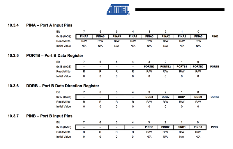
This was helpful in mapping the pins to the Eagle schematics:
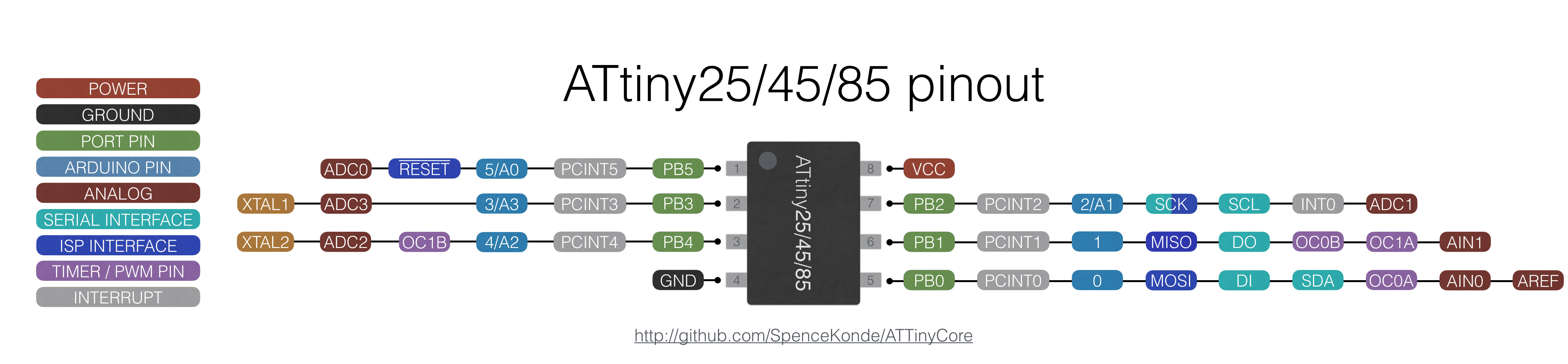 Attiny45 Pinout
Here’s the ATTiny44 Data sheet. Page 65/66 clarified why I needed to change the PORTB, DDRB, and PINB to A’s. The ATtiny44 uses both PBx and PAx pins, where the Attiny45 uses only PBx’s.
Screen shot of page 66: