15. Group Project: A Rube Gershenfeld Machine!
The work presented here represents the work of the Dassault Fab Lab students including: Alex, Aleza, Dan, Jose Tomas, Jose Luis and LaShawnda.
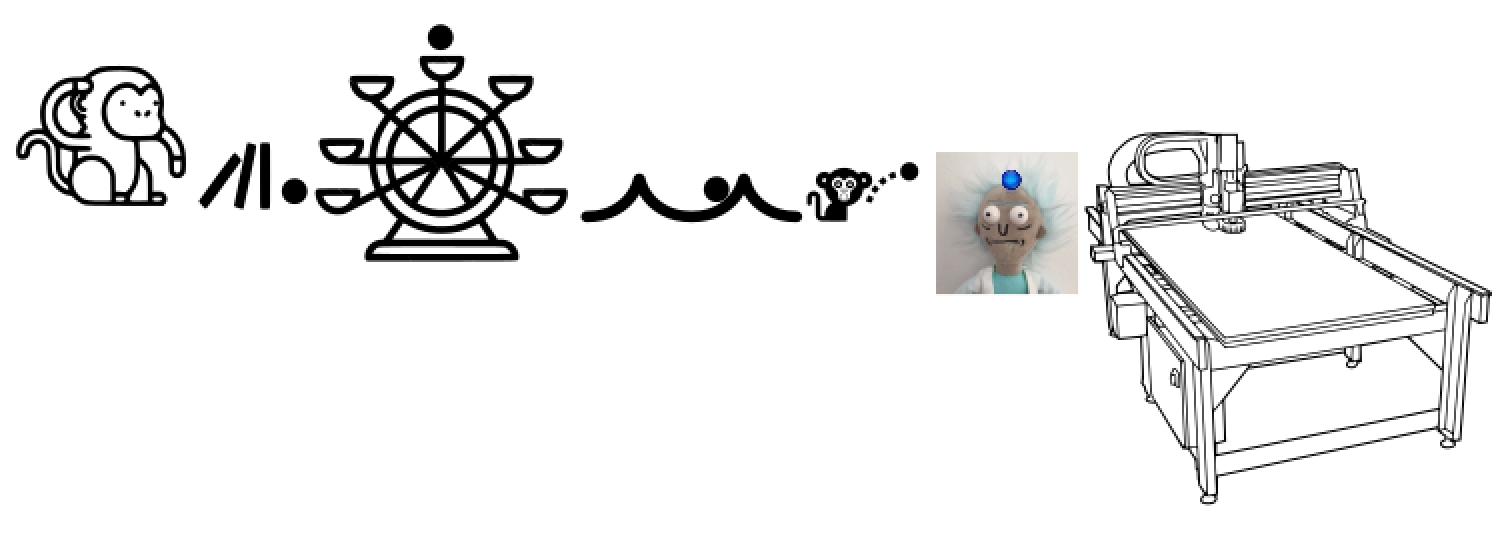
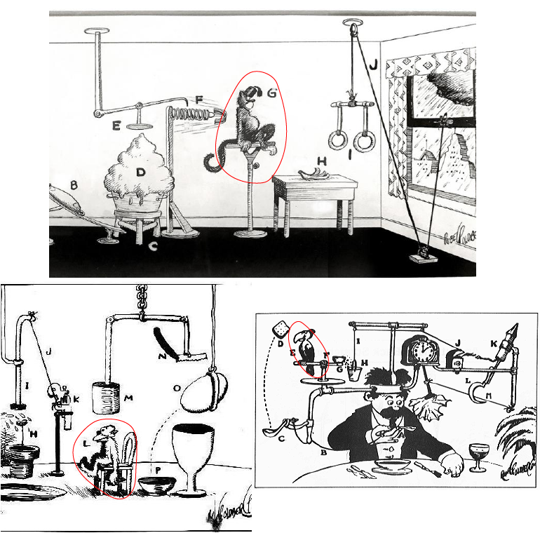
This week is the first half of our group project. We’ve decided to make a Rube Goldberg Machine! (We cleverly renamed it a Rube Gershenfeld Machine). Rube Goldberg was an American cartoonist who drew up overly engineered contraptions to accomplish a really simple task, like turning on a light switch. There’s tons of fun examples, one of our favorites is from the band, Ok Go.
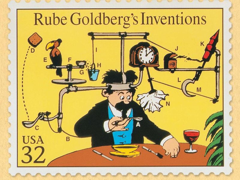 This image was kindly borrowed from Rube Goldberg, retrieved from the Smithsonian
We thought it would be fun to consider this machine for a Fab Lab. What about a series of contraptions - with automated acuation and mechanistic interactions - to turn on and start a CNC machine?
Here’s our group email thread that describes the idea:
Our rube goldberg machine’s task will be to press the two buttons needed to start the shopbot in our lab (the left mouse button and the pendant button). the shopbot will then cut out a piece of plywood which…in theory could be used to assemble a new r.g. machine, or even assemble itself, and thus we may very well tear a hole in the fabric of the spacetime continuum as we know it. :) See diagram below.
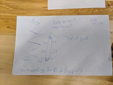
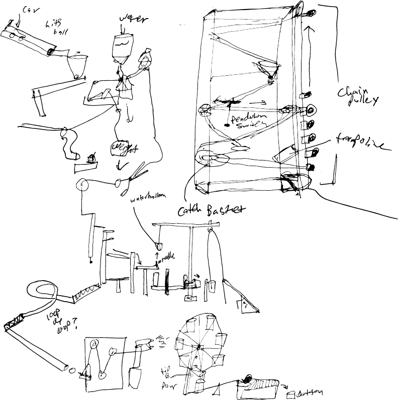
Our first group sketch, outlining major ideas:
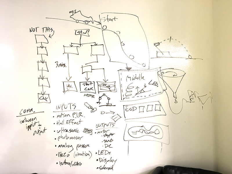
One thing we’re excited about is doing branching operations within the machine so as to avoid a linear progression. Meaning, multiple sequences could be happening at the same time, not just one module leads to another and another until the end.
Homework for Wednesday Bring sketches of 2 potential modules or subsystems for our r.g. machine. One of these must include an input or an output device.
End Tasks - Press two buttons:
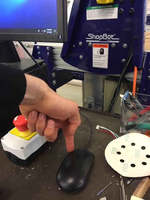 We’ll use either a solenoid to lightly press the mouse button. We’ll need to constrain the mouse so that it doesn’t move.
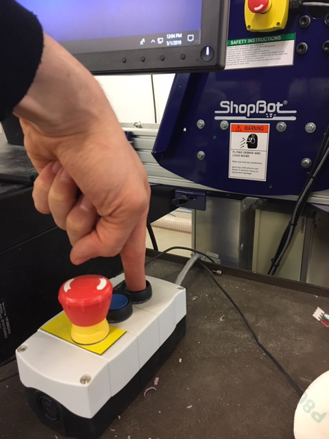 The start button involves more nuanced motion to depress. We think we’ll use an acutated lead screw to press this one.
Machine Diagram
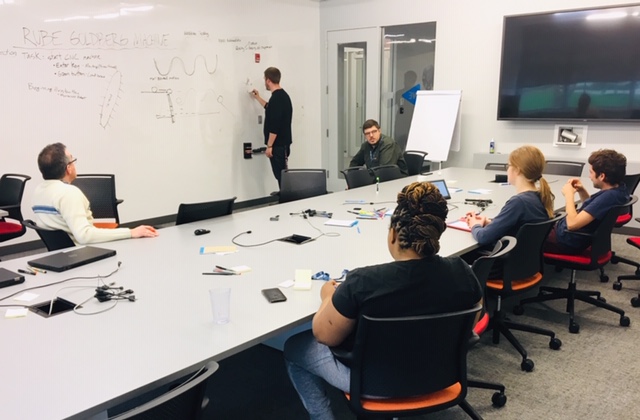 Here we are brainstorming on our machine!
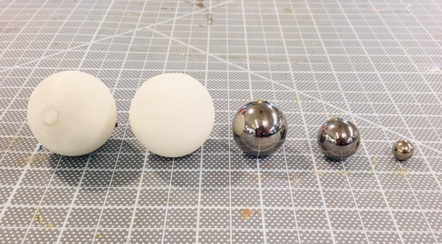 We 3D printed a few plastic balls - solid fill and semi-hollow - as well as purchased some steel - magnetic- balls. Sizes include 3/8”, 3/4”, 1”, and 1-1/2”.
Module 1 - A Conveyor Belt
Sketches
 Sketch 1: Ball down ramps (shopbot cut the ramps with grooves for the ball to follow? A notch in the vertical supports for them to slot in and angle?) Hits button - button triggers lifting device and maybe something else? Like one of the end buttons?
Lifting device can either be buckets on a wheel or a lead screw with a platform and guides. Maybe the guides end, platform rotates, ball falls/gets knocked off?
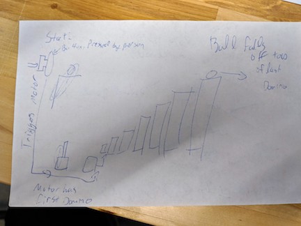 Sketch 2: The start of the system! Hit a button, trigger the dominoes falling over. Motor? Solenoid? The ball in a groove on the last one falls into the rest of the apparatus to start it. The domino setup can be a fun way to make the thing optionally larger.
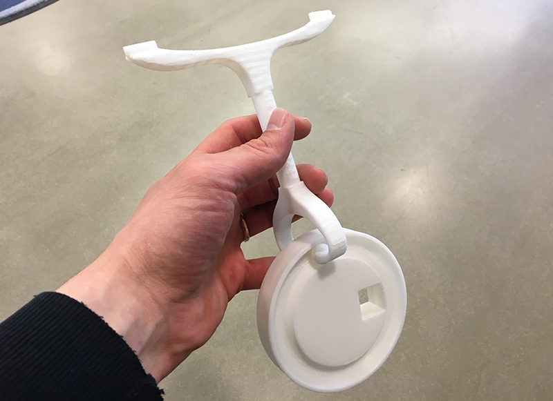
Prototype 1 - 3D prints
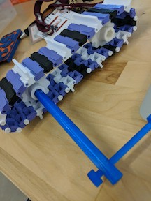 I also designed connectors for it to link everything and put them in (pictured above), but in retrospect I think fishing line would work better.
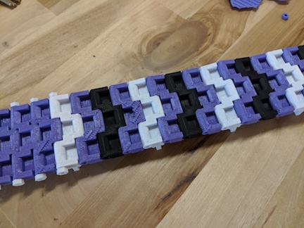 Now to design the sprocket - basically measure the underside of the cavity (pictured above), put it into a gear with like 10 teeth, and then make a spot for a connector.
Module 2 - A Wave Machine
Here’s Dan’s Module - an idea for a wave machine that carries a ball across an undulating surface.
Sketches
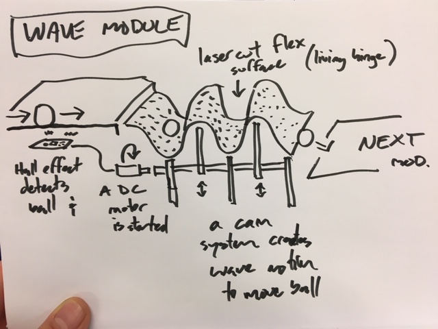
It will use a hall sensor to detect the (magnetic) ball coming in and it would start the DC motor spinning. The DC motor is connected to a cam shaft with alternating high/low positions that would push and pull on a laser cut living hinge surface. The ball will pass through the wave and be sent off to another module. My inspiration for this was this video.
I need to design the cam system-probably 3D print it- and spec out the motor and make the Hall Sensor board. I’ll start with the Mechanical design and prototyping this week.
Prototype 1 - Cardboard Mechanics (are no good!)
This prototype demonstrates the theory, however, motion isn’t really happening, at all. The main culprit is friction due to inprecise cuts. Another culprit is unrestrained motion - too much slop in the system.
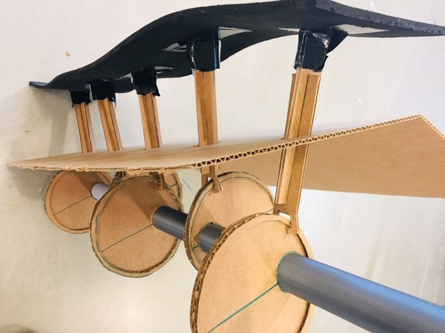
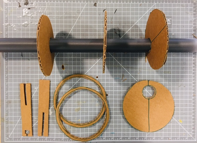 Here are the camshaft parts. I’m using cardboard and a found 3D printed tube for now (it was printed in the Gigabot). This mock-up is oversized for the sake of working with cardboard. The final scale will be 1/2 this size (at max).
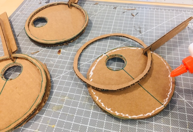 Gluing hand-cut parts together isn’t the most precise operation. These errors will likely add up. :(
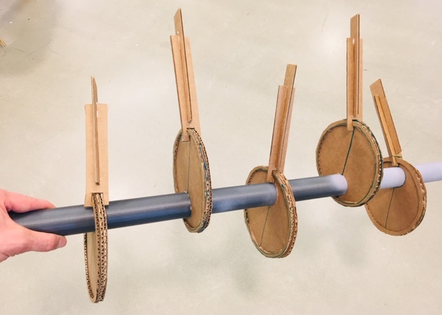 Here’s the camshaft assembled with pistons in place. I’ll need to secure the pistons so they only go up and down.
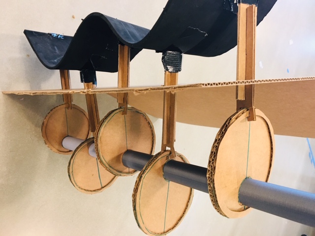
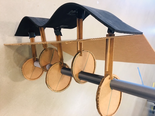 Here’s the starting state, 0 degrees - alternating up/down camshaft positions, with a neoprene rubber sheet secured to the tops.
 Here’s rotation at 90 degrees, notice that the wave is flattened out at this point. This also illustrates a design flaw: the piston isn’t always normal to the wheel and not enough room is provided for it to pass through.
 Here’s rotation at 180 degrees, with the wave in the opposite frequency.
I’ll move on to 3d printing the pieces for the next prototype. I think this will work better than laser cutting wood, as that will have a lot of friction as well.
Prototype 2 - CAD & 3D prints
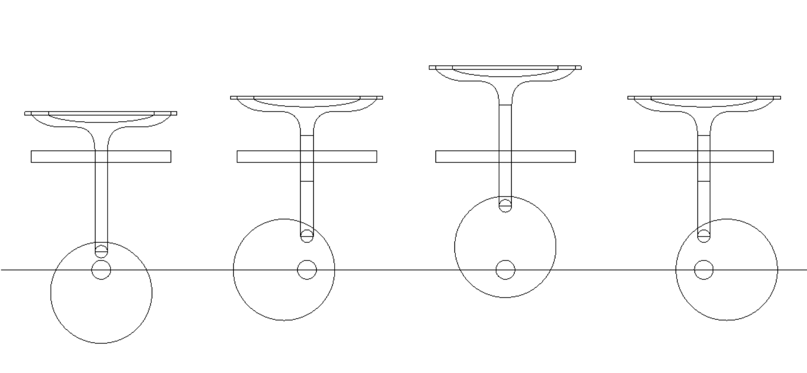 I started the CAD by drawing elevations of the profiles, then extruded the shapes into 3d.
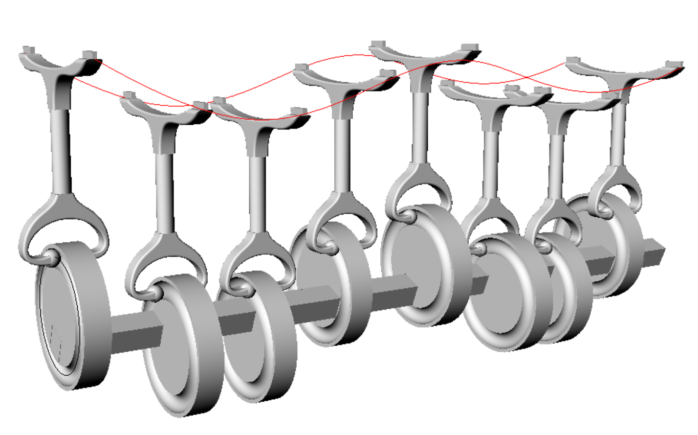 Everything thinks this won’t work, but I still do! They think the vertical shaft needs to rotate out of plane in order to fully cycle. The 3d print is in the oven. The square axel will prevent any slipage…tho it will limit the shape of the wave.
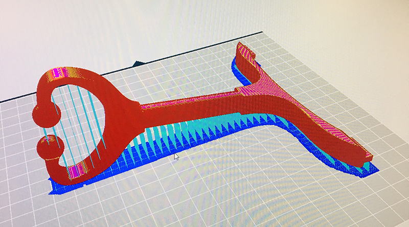 Not the easiest shape to 3D print efficiently - laying the part flat isn’t an option. In a perfect world I’d probably separate the end parts from the shaft and screw them together after printing. But who has time for that?
Module 3 - Chaos Monkeys
Sketches
Prototype 1 - A servo monkey
Prototype 2 - An elastic monkey

Automation
We will begin motorizing and automating these mechanical designs over the next 2 weeks.