8. Computer controlled machining
All this information is refered to Computer Controlled Machining class.
Assigment
- Make (design+mill+assemble) something big
The Machine
ShopBot Buddy
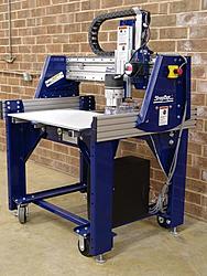
The ShopBot Buddy is designed for industrial, commercial, or residential applications cutting in wood, plastics, aluminum and other materials. The Buddy incorporates many of the same features as ShopBot’s full-size industrial systems, yet weighs less than 600 lbs. and occupies as little as 16 sq. ft. of floor space — and it comes with optional casters that allow you to move the tool easily for different applications in your shop. That makes them useful on the shop floor. They can be configured and reconfigured for specific production needs—Buddys are the agile production CNC solution.2.
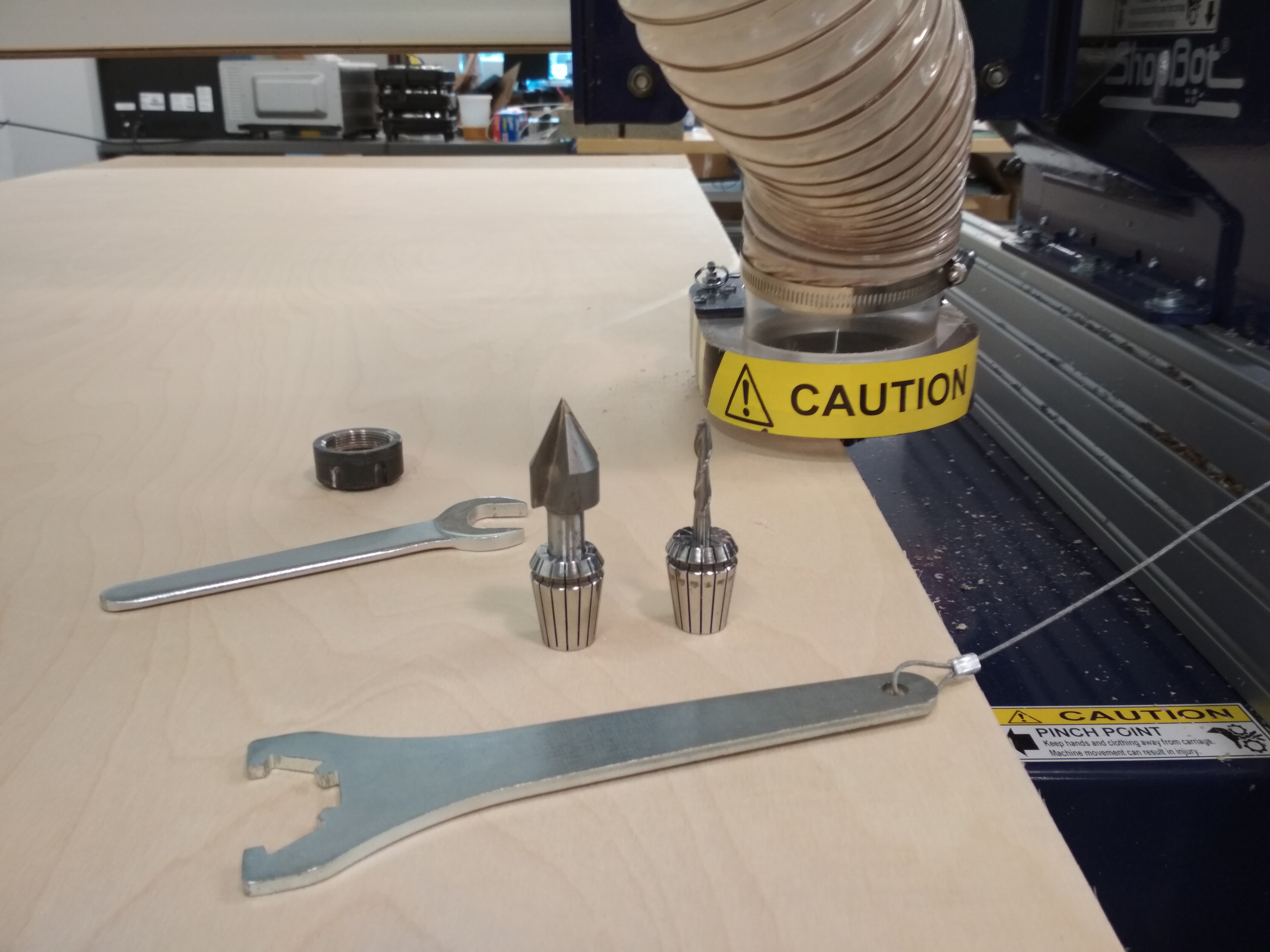
The Mills
I used 2 endmills for the whole process:
-
45° V Mill: I used this mill for the engraving operation.
-
1/4 2 Flute Downcut for the contour and Bore operations.
Objective
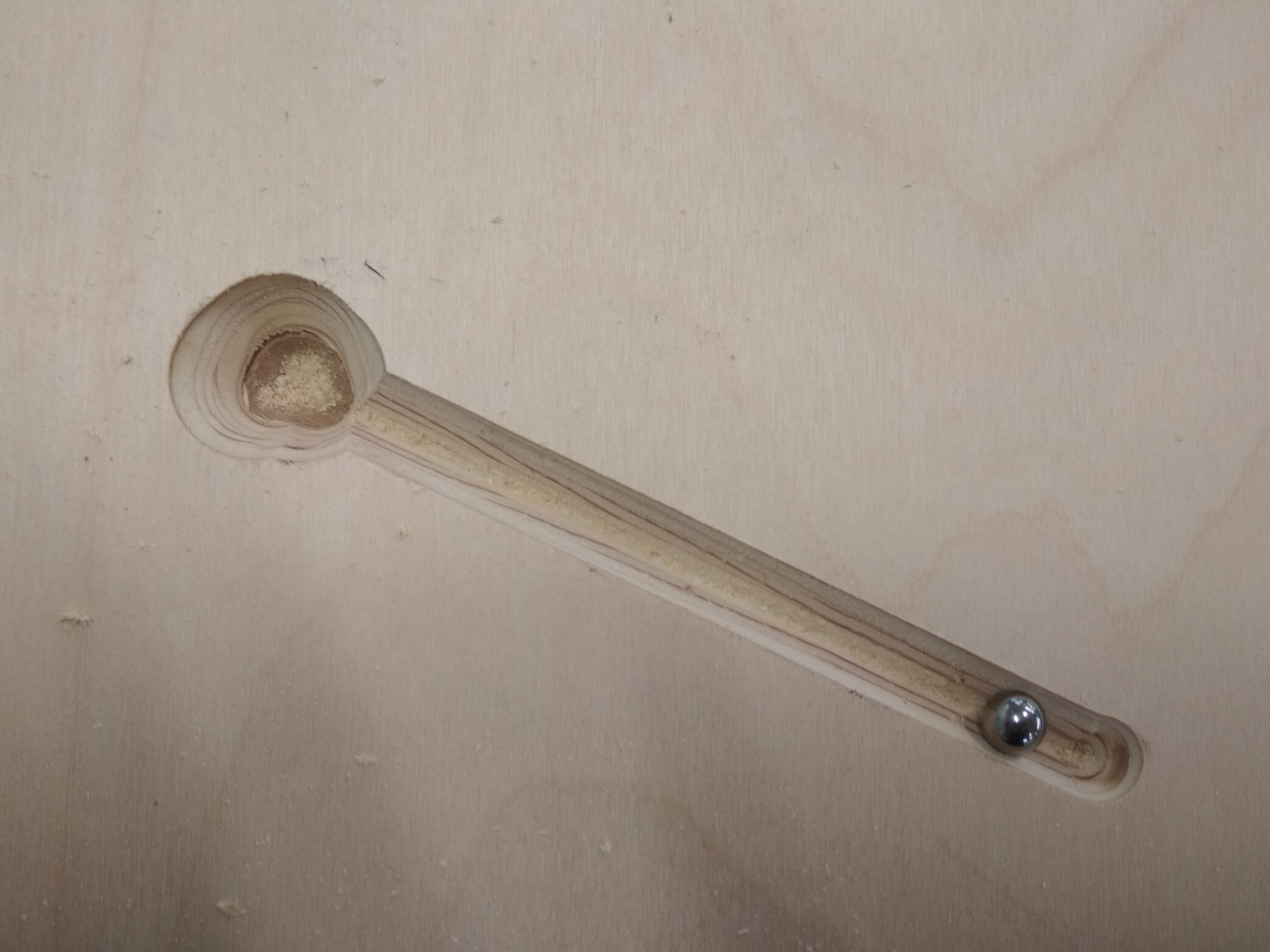
I did this weeks assigment in the context of the Machine Design group project; to see the whole project you can go to Dan Smithwick. The idea is to build a ramp with a path that a ball will follow to triger a conveyor.

Design
Models
Limitations of Milling
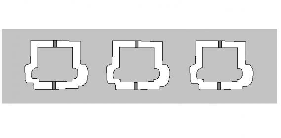
As milling technics consist on a high speed mill removing material from a stock piece, inside corners are a dificult part. It is imposible for a rotating tool to get a 90° corner, so your angles will always have a radius equal to the mills radius. This is reflected on the folowing image:
This brings a problem when you are looking to make parts that fits each other. As you can see in the image, to help the corners of the 90° corner to fit in a inner cut, you can use Relief Holes or Dogbones.
As you can see in the following images:
Insertar fotos d los real life dogbones.
Fusion 360 Manufacture Module
From high-efficiency roughing with Adaptative Claering to simlified control of multi-axis machines with Tool Orientation, Fusion 360 makes it easy to program your CNC machine, fast. Manufacture with 2.5, 3, 4 and 5-axis milling, probing, turning, mill-turning and profiling operations paired with powerfull post engine all included alongside porfessional design tools. 2
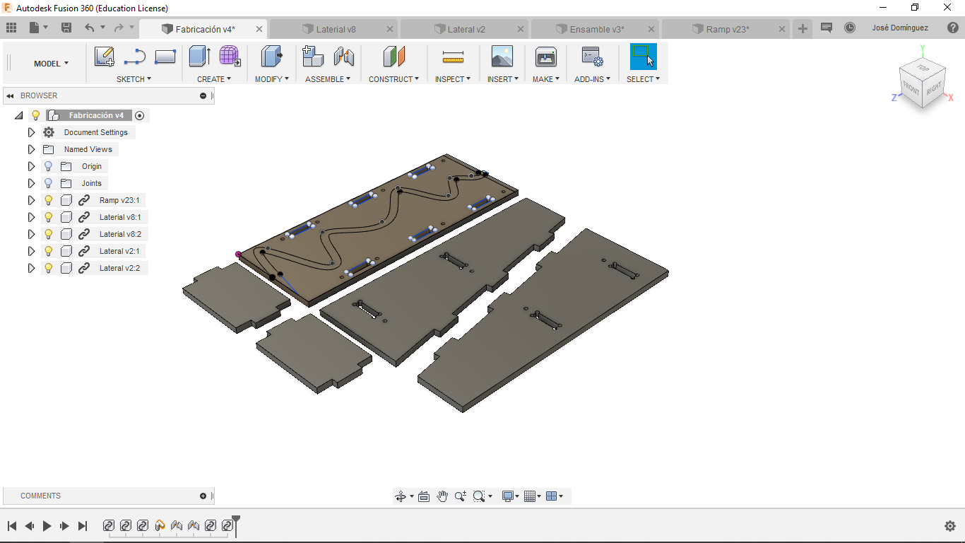
The first step is accomodate all parts as you will like to pats to be milled:
Setup
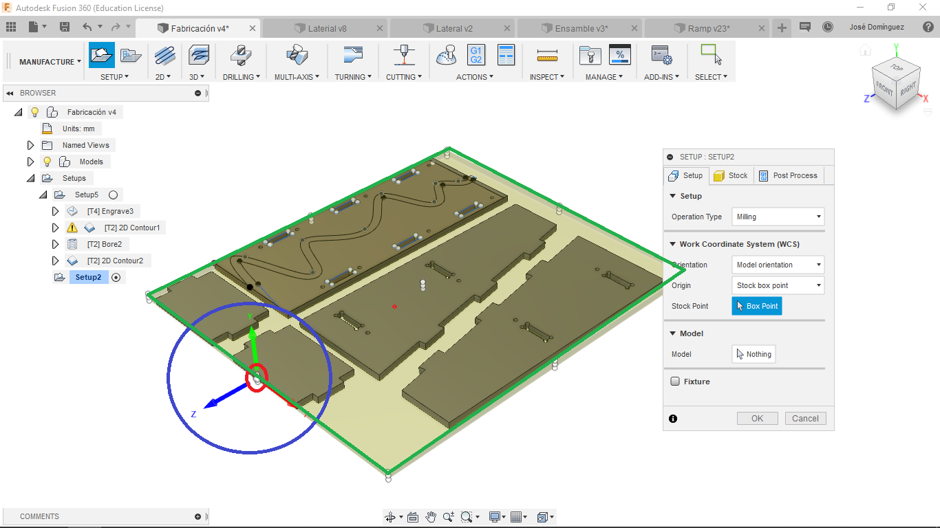
Then you will have to define the operation setup, the key parameters here are:
-
Work Coordinate System: It is important that this coordinate system is the same in your CAM than in your machine, if not, the machine would cut in diferent directions.
-
Stock: Define the measures of the stock that would allow the program to understand the material from where you are going to substract material from. This is also important in the simulation step I will explain forward.
-
Origin: Is the 0 point of the Work Coordinate System.
In the following image you can see the Origin (Red), Work Coordinate System (Blue) and Stock (Green) given at the begining of the setup:
Operations
Here I am going to list the operations I used, add the Fusion 360 oficial description of them and link the video tutorials:
Engrave: Engrave machines along the contours with V-shaped chamfer tools. Select the profile with Edges, Sketches or Faces. The tip of the tool is used to create sharp edges on the cavity corners.
Learn how to make this operation here
Contour: 2D Contour allows you to machine profiles. The machining area can be selected from Edges, Sketches or a Solid face. Typically a finishing operation, but Contour can be used to take multiple cuts.
Learn how to make this operation here.
Bore: Bore is used for helical milling into a hole or a boss, with straight or tapered walls. Select any internal or external Face to create the path. The heights and depths are automatically derived from the selected Face.
Learn how to make this operation here.
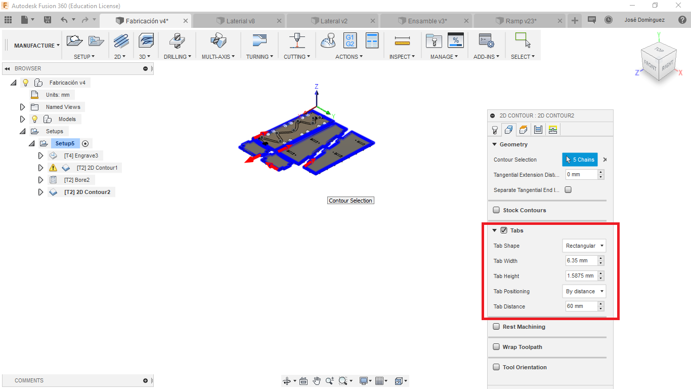
For the last contour operation I added Tabs:
Tabs fix the inside part to the stock, this keep the part your are cutting in the same position, that way the machine doesnt cut the part because it moved. Also it doesnt allow the part to fly away after been cutted.
Simulation
After the whole process, Fusion 360 allows the user to simulate the cut, giving alerts in case that a crash or a excess of material removal ocur.
José Tomás Domínguez (Joseto) on Vimeo.
Using the Machine
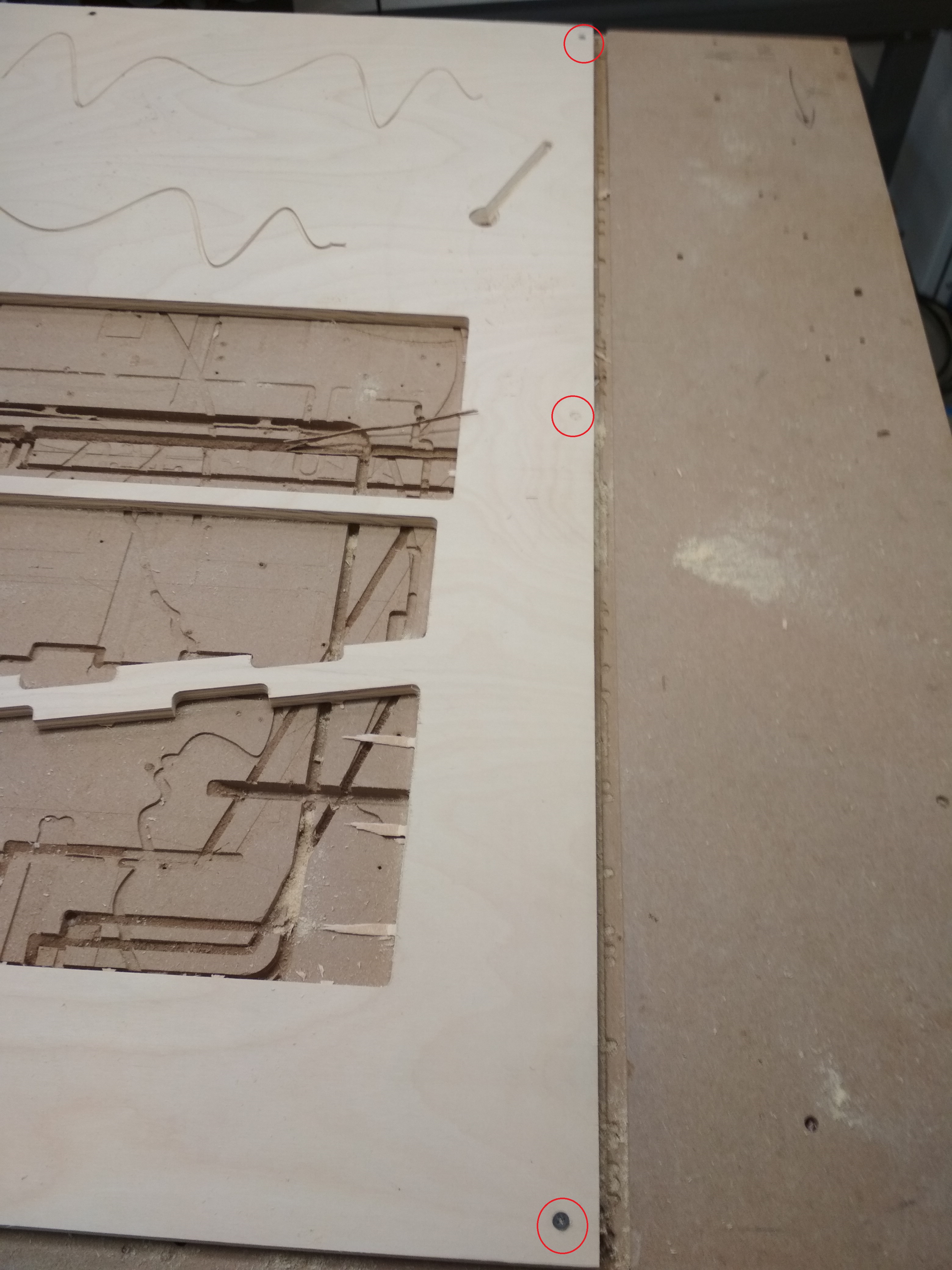
Fixing the Stock
In order to fix the sotck material to the sacrificial layer, I just put 3 screws in the border of it:
Setting the 0
The next step is to define the 0 for the machine, remember it has to fit the 0 we defined in the setup.
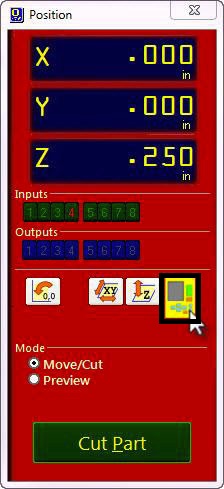
The Z process is based in the Shopbot internal code:
For this process you will have to put the aluminum plate in your layer defined as 0 plane , and the aligator clip to the mill:
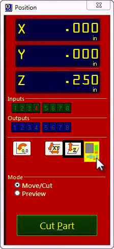
Run the Shopbot default program.
Then you will have to set the 0 for the X and Y axis, using the program enviorment that enables you to move the machine:
Move the machine manually to the point where you want the machine to start. Remember this point has to be the same one you set on your CAM.
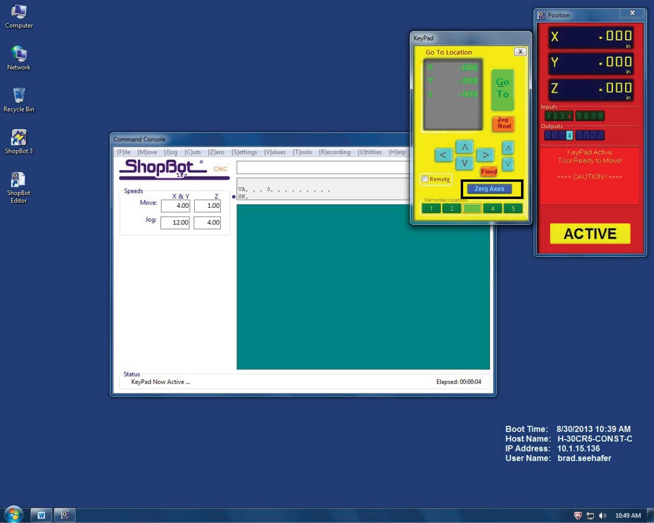
Then click on Zero Axes.
Troubleshooting
During the whol process I had 2 problems:
The whole point of the ramp is to make a path where the ball can travel to activate the Rube Goldebrg Machine. Sadly, the first to pathes I made wasn’t deep enough, and the ball just went off:
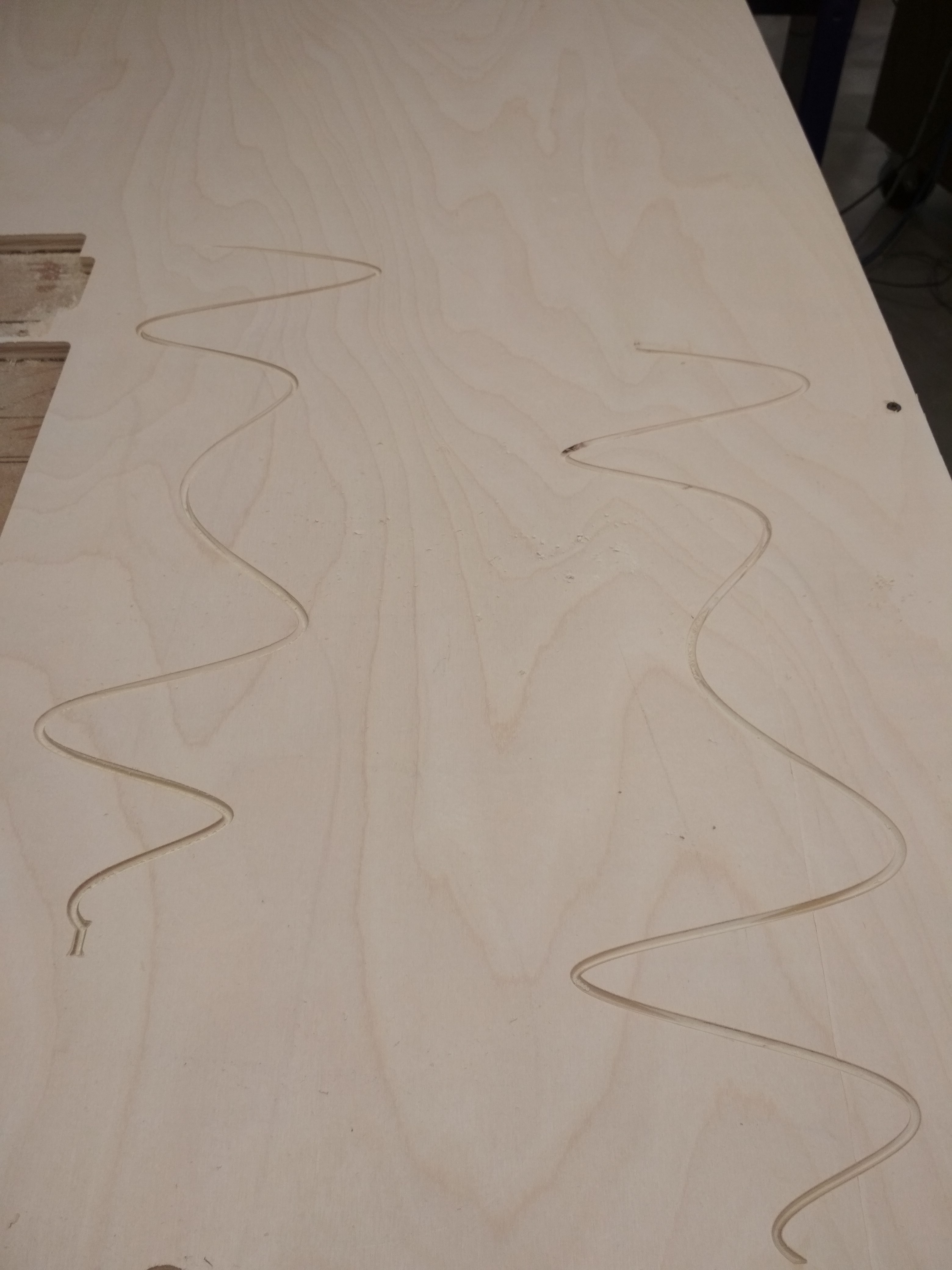
I solved it by macking the paths deeper.
Once I forgot to set the 0 in the Z axis, and the mill just cut down really deep:
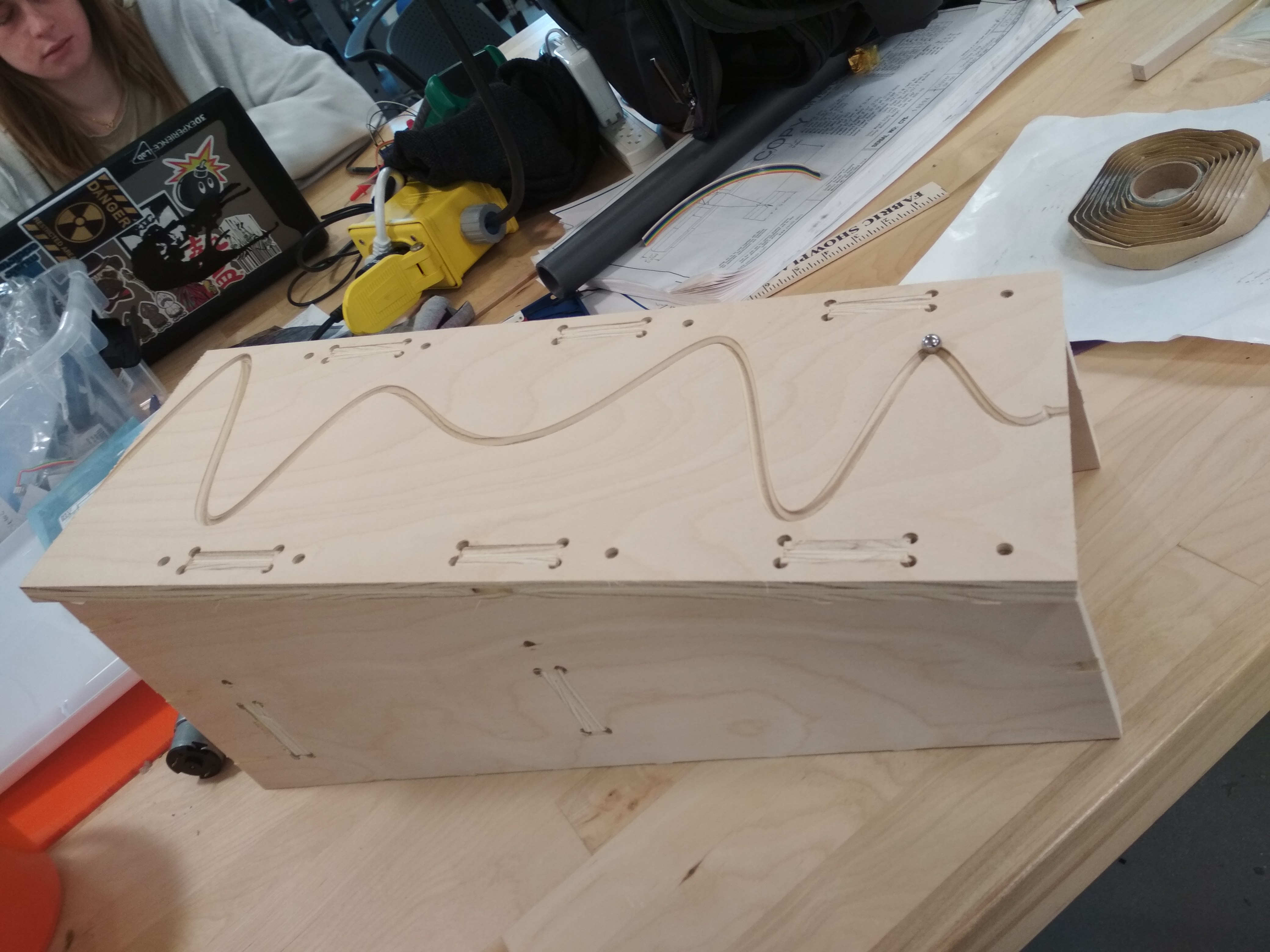
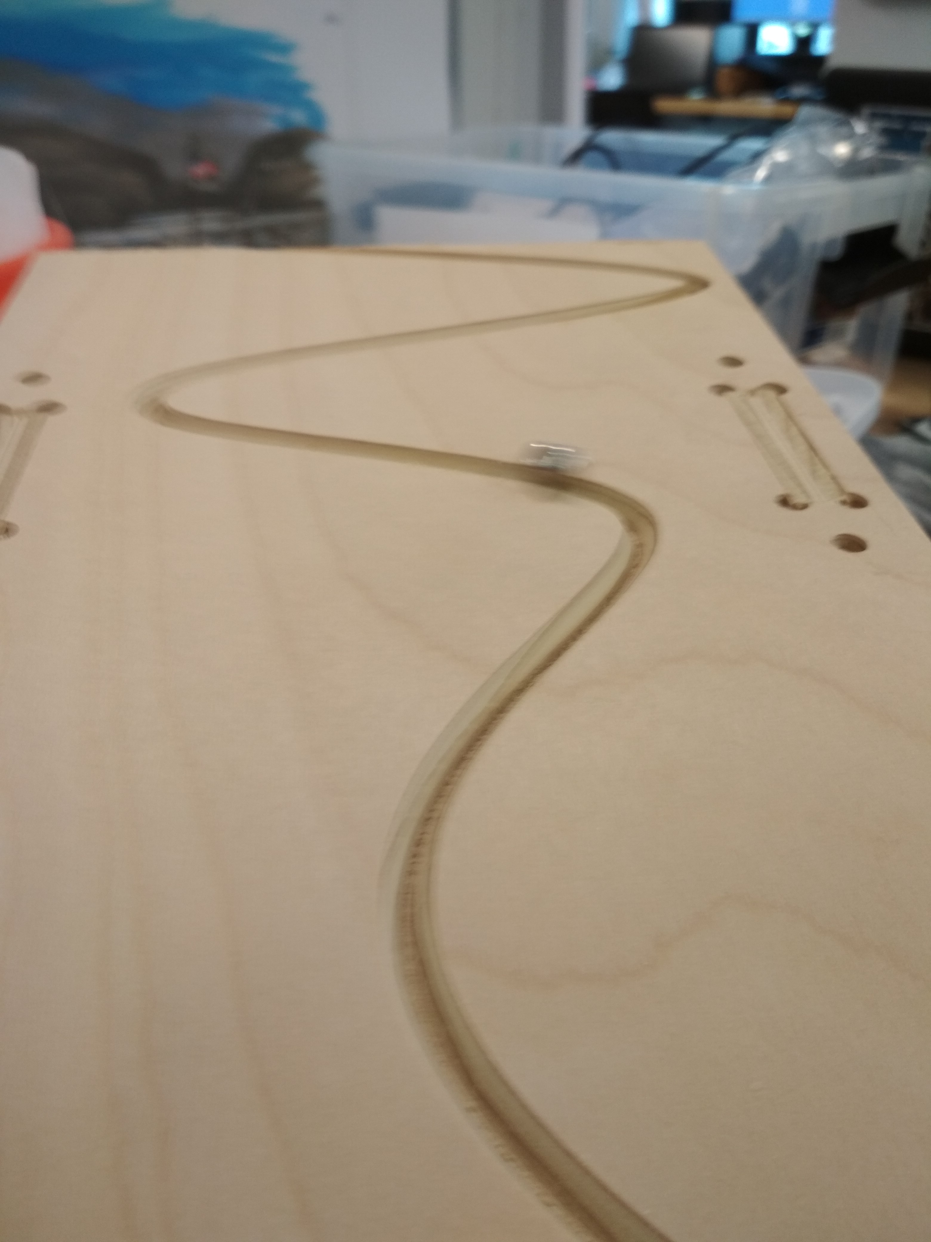
Final Result:
Download Links
-Ramp