15. Mechanical design
As a group we decided to buils a Rube Goldeberg Machine. My documentation is going to talk specifically about my job on it; if you want to see the full project go to Daniel Smithwick page.
Inspiration
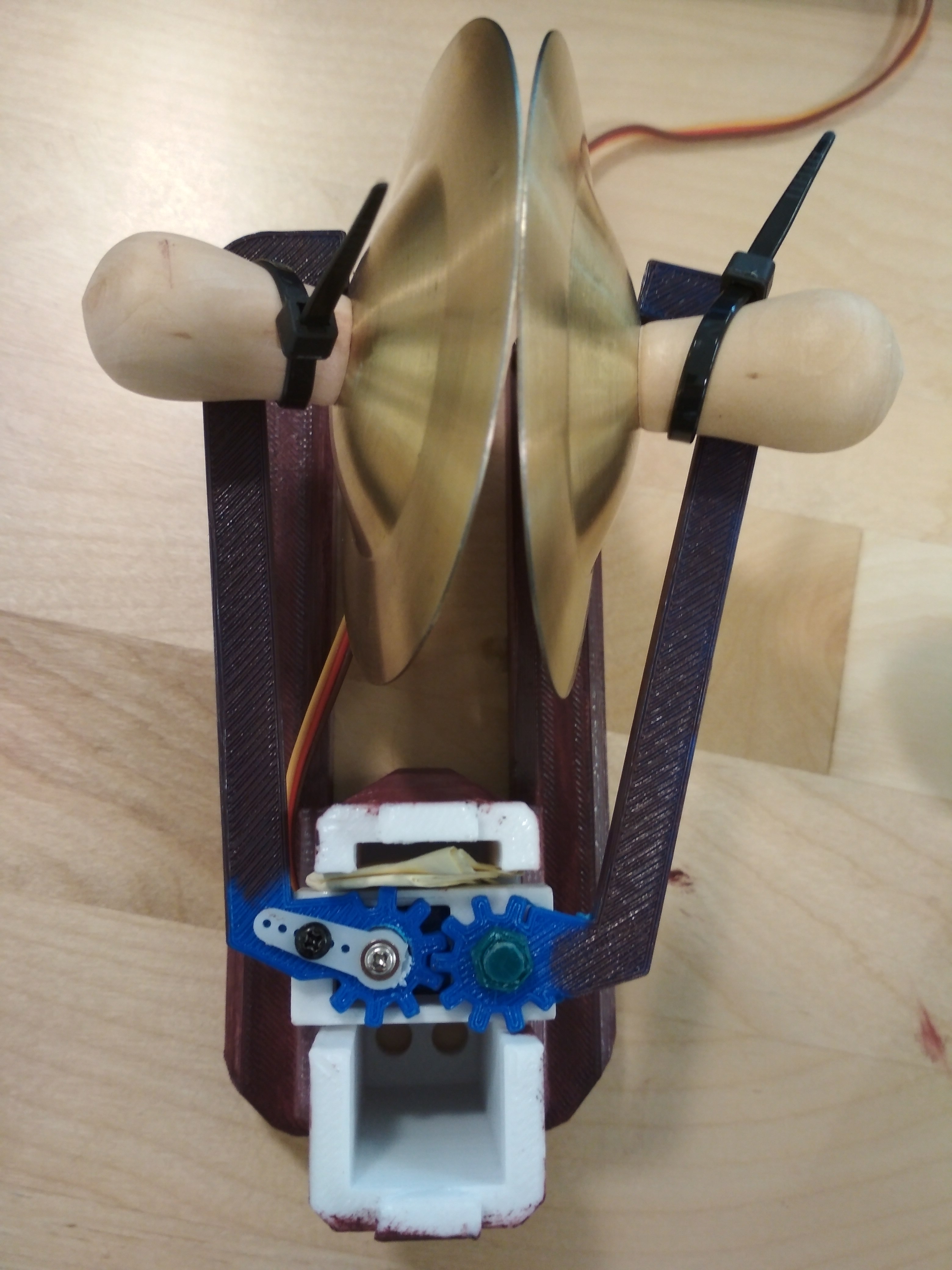
For this week I’m building a Scary Monkey:

It is going to be operated through a servo and a noise sensor.
As you can see in my classmate LaShawanda Lindsay-Dennis, the first step of the machine are a herd of monkeys make different noises that will hit a dominoe.
Mechanism
Concept
Gears are mechanisms that mesh together via teeth and are used to transmit rotary motion from one shaft to another. Gears are defined by two important items: radius and number of teeth. They are typically mounted, or connected to other parts, via a shaft or base.

This mechanism is mimicking a robot claw servo motor system:

As you can see uses uses a gear system tu take the rotational movement from the servo motor into both pincers.
My Parts:
After the 3D Printer
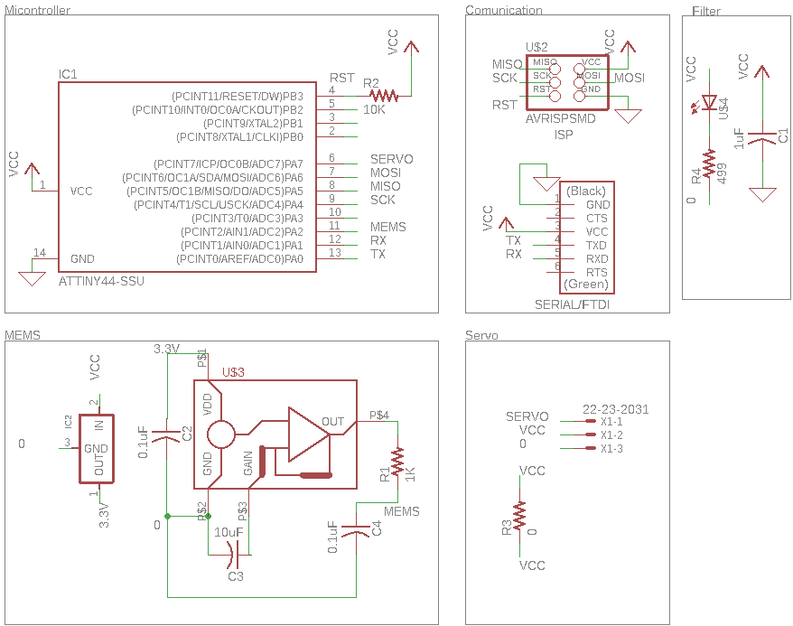
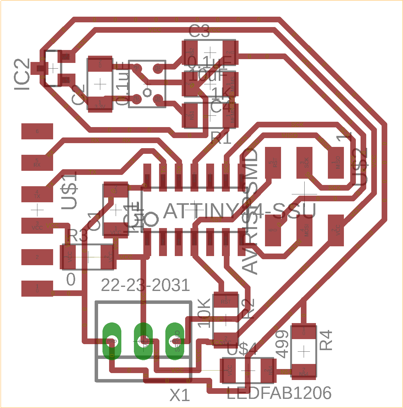
Electronics
The Board
The Code
The code is a mixture of Neil’s MEMS code and Software PWM code.
#include <avr/io.h>
#include <util/delay.h>

#define output(directions,pin) (directions |= pin) // set port direction for output
#define set(port,pin) (port |= pin) // set port pin
#define clear(port,pin) (port &= (~pin)) // clear port pin
#define pin_test(pins,pin) (pins & pin) // test for port pin
#define bit_test(byte,bit) (byte & (1 << bit)) // test for bit set
#define bit_delay_time 102 // bit delay for 9600 with overhead
#define bit_delay() _delay_us(bit_delay_time) // RS232 bit delay
#define half_bit_delay() _delay_us(bit_delay_time/2) // RS232 half bit delay
#define char_delay() _delay_ms(10) // char delay
#define serial_port PORTA
#define serial_direction DDRA
#define serial_pin_out (1 << PA1)
#define NPTS 100 // points in buffer
#define admux 0b10000010

#define PWM_port PORTA
#define PWM_direction DDRA
#define PWM_pin_1 (1 << PA7)

#define loop_count 10

int trigger = 950;
int i=0;

void put_char(volatile unsigned char *port, unsigned char pin, char txchar) {
   //
   // send character in txchar on port pin
   //    assumes line driver (inverts bits)
   //
   // start bit
   //
   clear(*port,pin);
   bit_delay();
   clear(PWM_port, PWM_pin_1);
   output(PWM_direction, PWM_pin_1);
   //
   // unrolled loop to write data bits
   //
   if bit_test(txchar,0)
      set(*port,pin);
   else
      clear(*port,pin);
   bit_delay();
   if bit_test(txchar,1)
      set(*port,pin);
   else
      clear(*port,pin);
   bit_delay();
   if bit_test(txchar,2)
      set(*port,pin);
   else
      clear(*port,pin);
   bit_delay();
   if bit_test(txchar,3)
      set(*port,pin);
   else
      clear(*port,pin);
   bit_delay();
   if bit_test(txchar,4)
      set(*port,pin);
   else
      clear(*port,pin);
   bit_delay();
   if bit_test(txchar,5)
      set(*port,pin);
   else
      clear(*port,pin);
   bit_delay();
   if bit_test(txchar,6)
      set(*port,pin);
   else
      clear(*port,pin);
   bit_delay();
   if bit_test(txchar,7)
      set(*port,pin);
   else
      clear(*port,pin);
   bit_delay();
   //
   // stop bit
   //
   set(*port,pin);
   bit_delay();
   //
   // char delay
   //
   bit_delay();
   }

int main(void) {
   //
   // main
   //
   static unsigned char array_lo,array_hi;
   //
   // set clock divider to /1
   //
   CLKPR = (1 << CLKPCE);
   CLKPR = (0 << CLKPS3) | (0 << CLKPS2) | (0 << CLKPS1) | (0 << CLKPS0);
   //
   // initialize output pins
   //
   set(serial_port, serial_pin_out);
   output(serial_direction, serial_pin_out);
   //
   // init A/D
   //
   ADMUX =  admux;
   ADCSRA = (1 << ADEN) // enable
      | (1 << ADPS2) | (1 << ADPS1) | (0 << ADPS0); // prescaler /64
   //
   // main loop
   //
      DDRA |= (1 << PA0);
   while (1) {
      //
      // send framing
      //
      put_char(&serial_port, serial_pin_out, 1);
      char_delay();
      put_char(&serial_port, serial_pin_out, 2);
      char_delay();
      put_char(&serial_port, serial_pin_out, 3);
      char_delay();
      put_char(&serial_port, serial_pin_out, 4);
      char_delay();
      //
      // free-running sample loop
      //
         //
         // initiate conversion
         //
         ADCSRA |= (1 << ADSC);
         //
         // wait for completion
         //
         while (ADCSRA & (1 << ADSC))
            ;
         //
         // save result
         //
         array_lo = ADCL;
         array_hi = ADCH;
         int value = 256*array_hi+array_lo;
         if (value>trigger){
            while(1){
               for (i = 0; i < loop_count; ++i) {
               set(PWM_port,PWM_pin_1);
               _delay_us(1000);
               clear(PWM_port,PWM_pin_1);
               _delay_us(19000);
         }
      //
      // 1.5 ms on time, both
      //
            for (i = 0; i < loop_count; ++i) {
               set(PWM_port,PWM_pin_1);
               _delay_us(1500);
               clear(PWM_port,PWM_pin_1);
               _delay_us(18500);
         }
      //
      // 2 ms on time, both
      //
            for (i = 0; i < loop_count; ++i) {
               set(PWM_port,PWM_pin_1);
               _delay_us(2000);
               clear(PWM_port,PWM_pin_1);
               _delay_us(18000);
         }

      //
      // 1 ms on time, channel 1
      //
            for (i = 0; i < loop_count; ++i) {
               set(PWM_port,PWM_pin_1);
               _delay_us(1000);
               clear(PWM_port,PWM_pin_1);
               _delay_us(19000);
         }

      //
      // 1.5 ms on time, channel 1
      //
            for (i = 0; i < loop_count; ++i) {
               set(PWM_port,PWM_pin_1);
               _delay_us(1500);
               clear(PWM_port,PWM_pin_1);
               _delay_us(18500);
         }
      //
      // 2 ms on time, channel 1
      //
            for (i = 0; i < loop_count; ++i) {
               set(PWM_port,PWM_pin_1);
               _delay_us(2000);
               clear(PWM_port,PWM_pin_1);
               _delay_us(18000);
         }
      }
         }
         }
      }
Video
Troubleshooting
Servo’s Arduino Library
When I was testing the board I dicided to use arduino code for the servo thinking it would be easier. Sadly it wansn’t :(.
The ATtiny boards doesn’t work with the standard Servo library that the Arduino IDE has, it has to use a Software PWM, to fix this, the arduino community has built the Software_Servo; the description of it is:
The Software Servo Library can drive servos on all of your pins simultaneously. The API is patterned after the wiring.org servo library but the code is different. You are not limited to 8 servos, but you must call the SoftwareServo::refresh() method at least once every 50ms or so to keep your servos updating.
The code I built with with this library is the following:
#include<SoftwareServo.h>

SoftwareServo myServopan; //create a servo object.
int angle = 0;
void setup()
{
myServopan.attach(7); //attach the servo to pin 3
myServopan.write(angle);
}
//sweep the servo
void loop()
{
// scan from 0 to 180 degrees
for(angle = 0; angle < 180; angle++)
{
myServopan.write(angle);
delay(15);
SoftwareServo::refresh();
}
// now scan back from 180 to 0 degrees
for(angle = 180; angle > 0; angle--)
{
myServopan.write(angle);
delay(15);
SoftwareServo::refresh();
}
}