Kidsulator
How could we teach kis simple math operations with a fun and interactive way?
Well, based on our projects in the company, mostly we are focusing to change the education from formal to informal learning. So, I was thinking if I could contribute company goals and create a game-based education. FAB Academy gives this chance to come up with this project to how we could teach kids simple math operations in a fun and interactive way. That could interact with kids to start learning the four simple operations of math (addition, subtraction, multiplication, and division). This project targeting elementary schools for the first three levels.
Kidsulator content three main things which are (2D, 3D, and Electronics). Top par was design using Onshape software also the bottom because Onshape it gives you a multi-function and friendly interface user. I design the microcontroller board using Eagle software to meet my requirements. I use sets of components such as LCD, push buttons, potentiometers, LED, and buzzer. Kidsulator was programming to choose two different programs either simple way to learn math or the program will choose difference results and ask you to complete the equation.
In the brainstorming, the project will contain the following as general:
- Circuit implementation
- Arduino
- 3D Printes design
- 2D Design and laser cutting parts
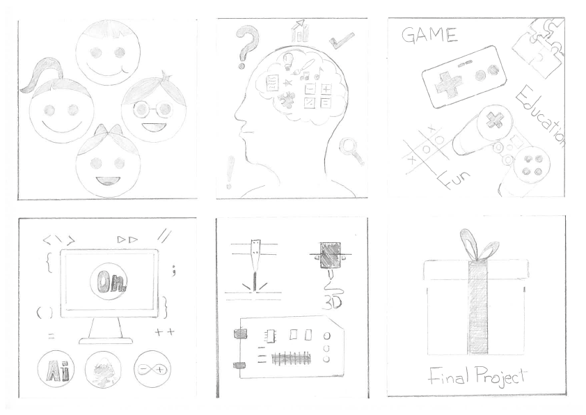
I did an initial illustration of my project that contains drawings describing the main objectives of having this project.as showing bellow.
As for the electronics part of the project, it will be simple and easy to do and use at the same time. It's all about creating a system to make the calculations (adding, subtracting, multipling, and dividing) the numbers that include two digits each (4 bits each). the result could be 4 digits maximum. The idea is to make an interactive educational system instead of having somting fixed and with no interaction as usual tools.
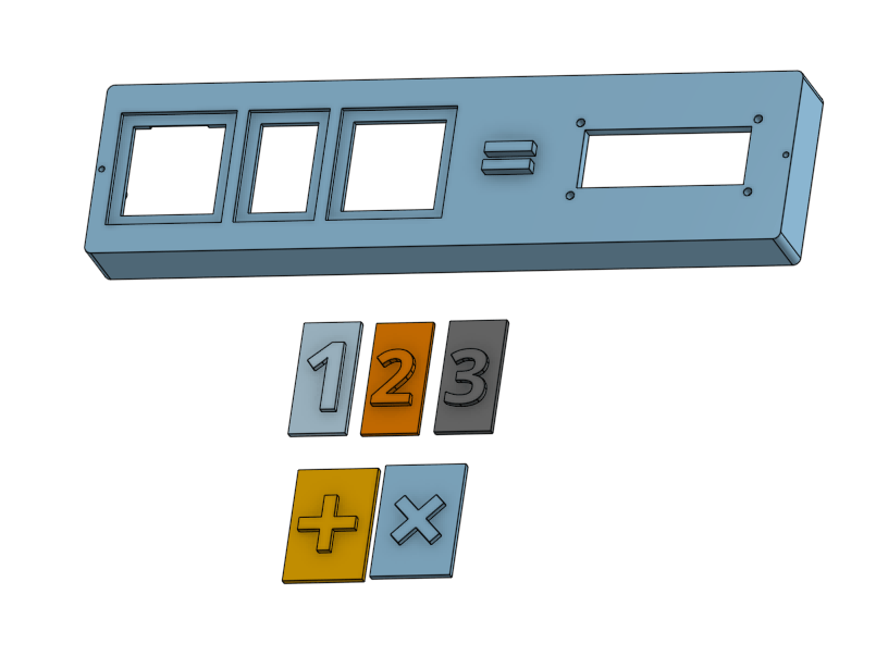
I have done an initial modeling using Onshape to start imagination the project parts and how it works!
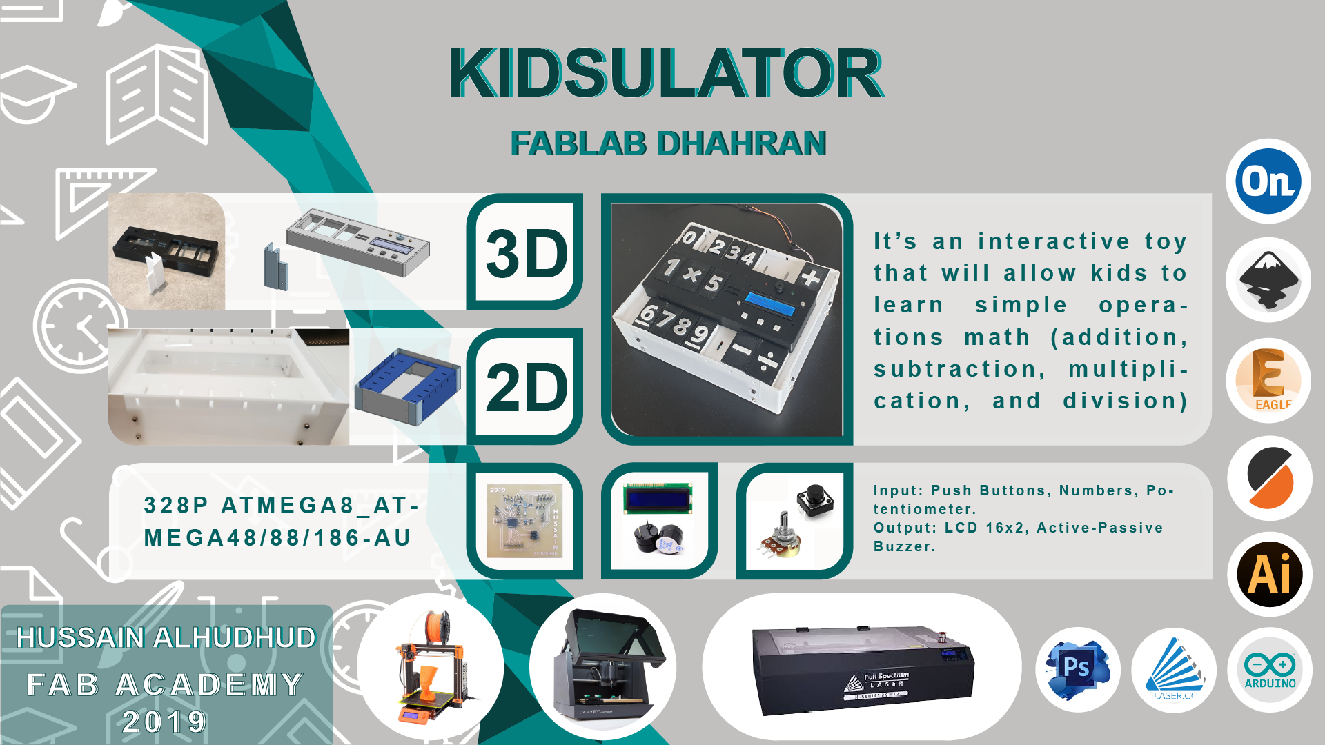
Poster
Bill of Materials
Material |
Quantity |
Cost USD |
Note |
Where you can get it |
Filament PETG |
300 g |
12 |
|
|
Acrylic |
3 sheets |
10 |
50 cm x 30 cm |
Local |
Screws |
30 pieces |
1 |
3mm |
|
LCD 16x2 |
1 |
5 |
|
|
Push Buttons |
3 |
1 |
|
|
Potentiometer |
1 |
3 |
|
|
PCB Coper Board |
4 |
6 |
15mm x 15mm |
|
Header Pins |
30 |
5 |
|
|
SMD Capacitors |
2 |
0.16 |
|
|
SMD Resistors |
4 |
0.4 |
|
|
USB Cable |
1 |
5 |
|
Total cost of materials is 48.56 $ USD
Design and Fabrication
It relied on in the design Onshape program that was used in many of the previous assignments:
2D Design
The following image is the sketch of bottom case cut by laser cutter
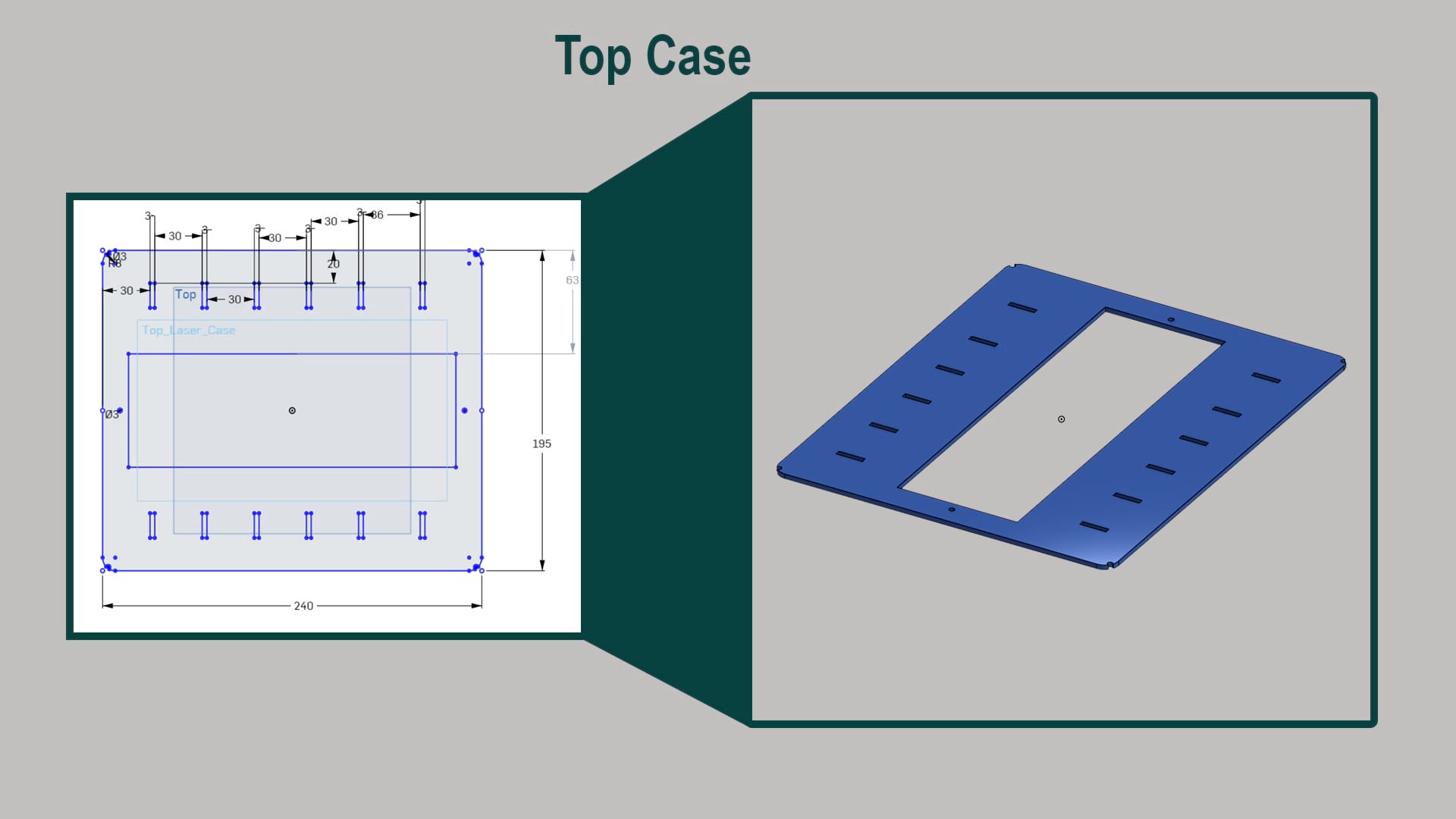
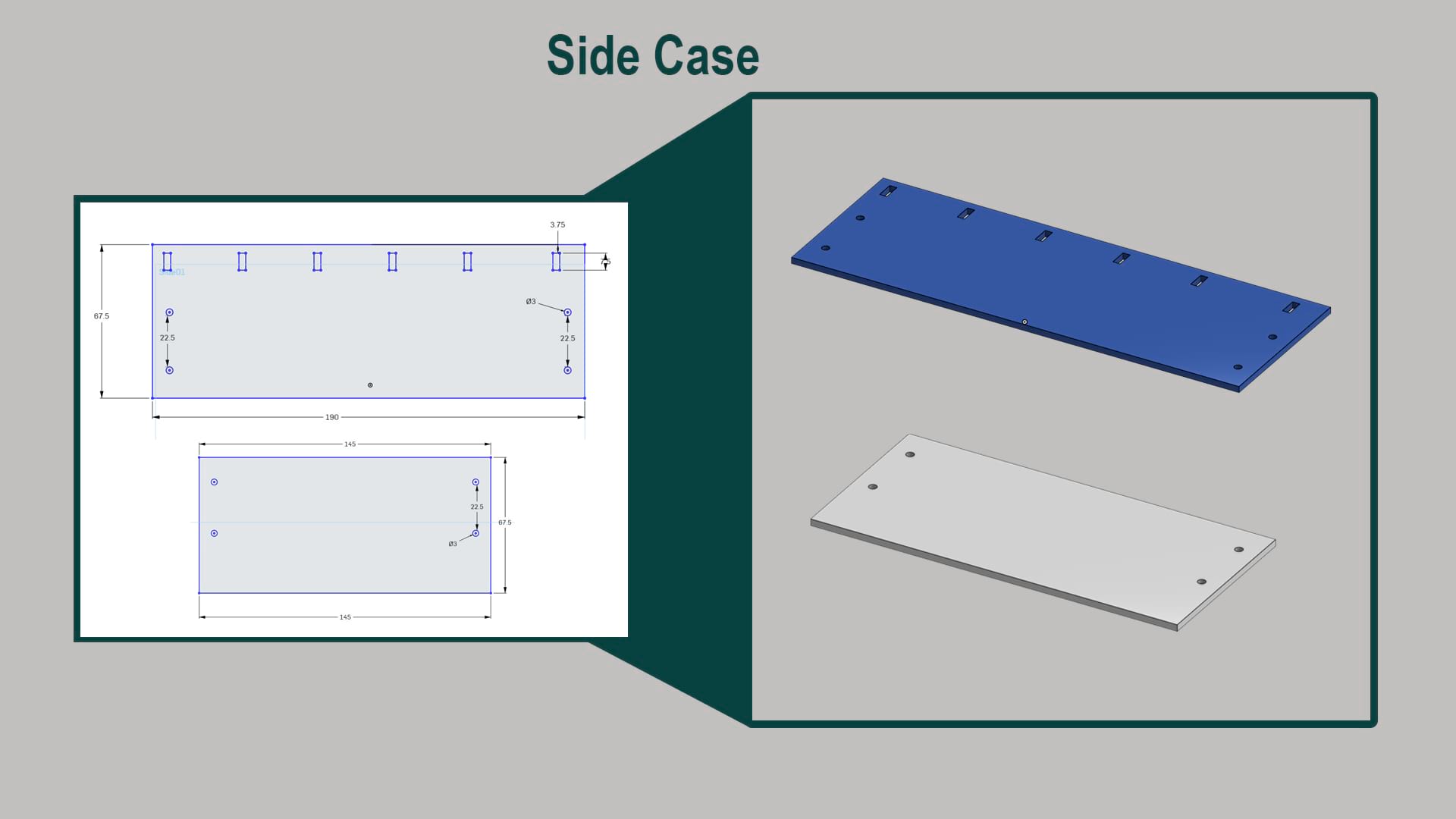
The dimensions of the top cover case which takes a hole that is going to hold top 3D print later on where the main part of the project will be install
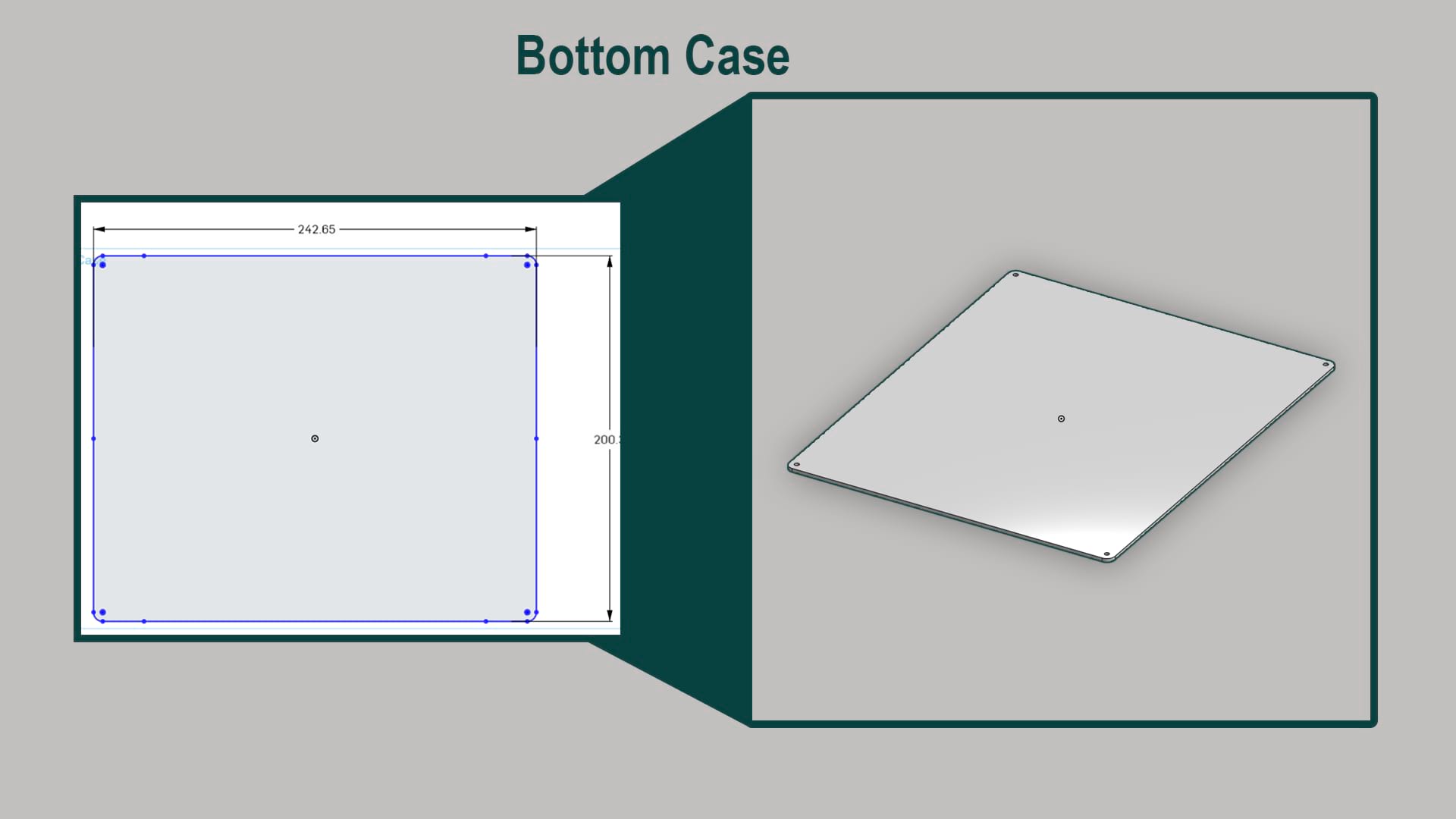
Bottome case dimensions of the case that cutting by laser cutter
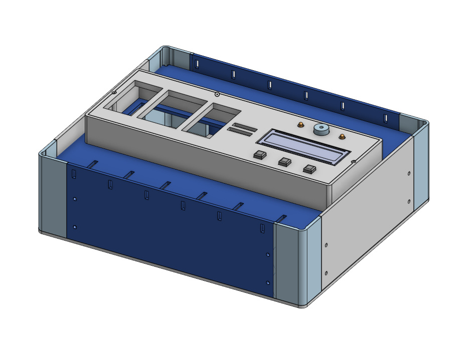
A render of the case how is going to look likes
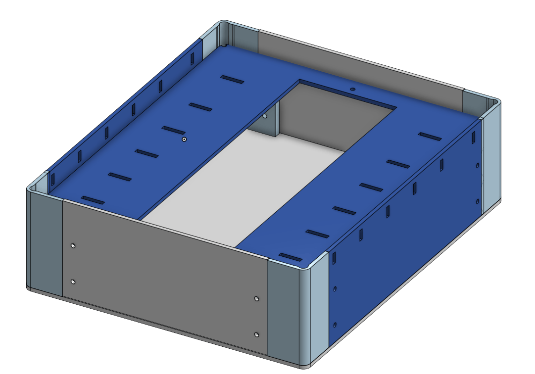
A render of the case how is going to look likes
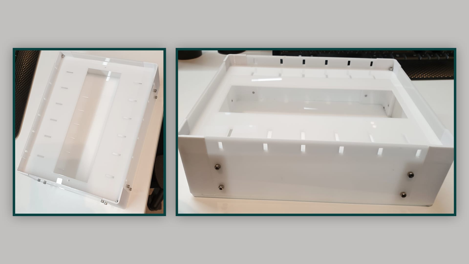
The acrylich case after assembled
_____________________________________________________________________________________________________
3D Design
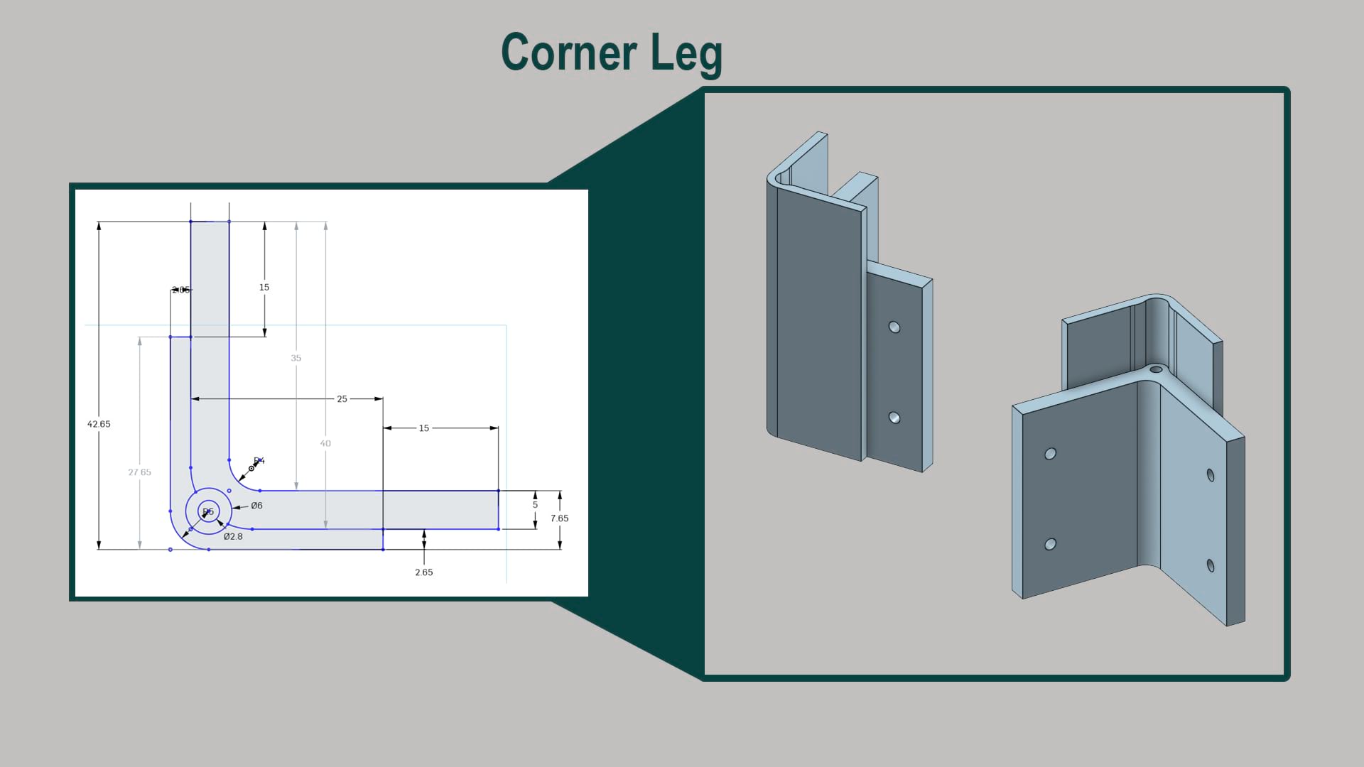
Sketching the corner leg that needs to use to build a case (box) that was cut by laser cutter in the previous section
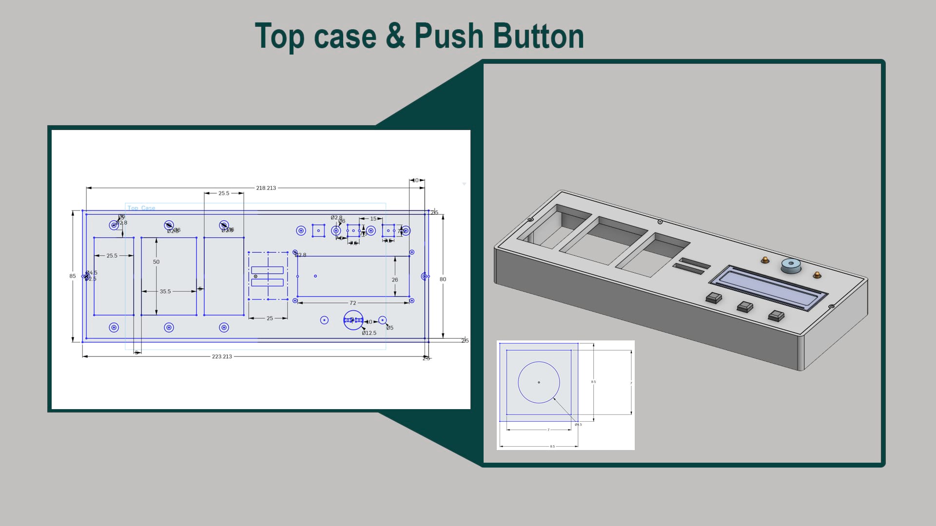
Measurements to build the top part of the project which include LCD, Push buttons and LED as well as Buzzer and the main part to add and read numbers
Onshape if you would like to check it out
To download all files goes down to the page you will find all the files need
A full render of the project
A view for final project
_____________________________________________________________________________________________________
PCB
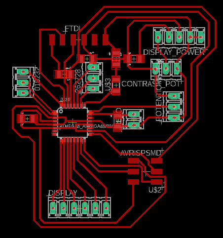
For Electronic Design, I started by modifying the satcha board, but modifying it to have an LCD, 2 LEDs and buzzer for Output, and push buttons and digital inputs to read the numbers from my final project. The general schematic and board are shown below:
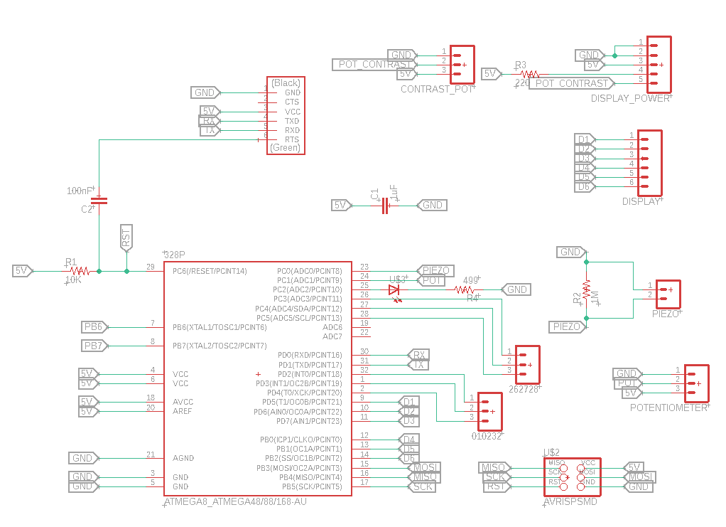
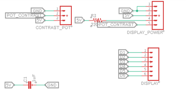
The following close-up shows the output elements
The following close-up shows the input elements. Focused on pins , 11, A2, A5, A4, A3, A1, 4, 3, 2, A0, 1, 0 and 1
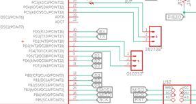
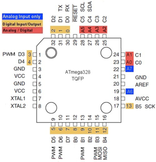
And are connected to the ATMAEGA using its pins which I found in the datasheet.
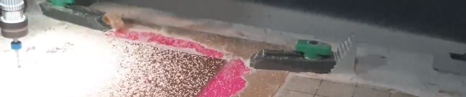
After the design, I used the carvey machine to cut the board.
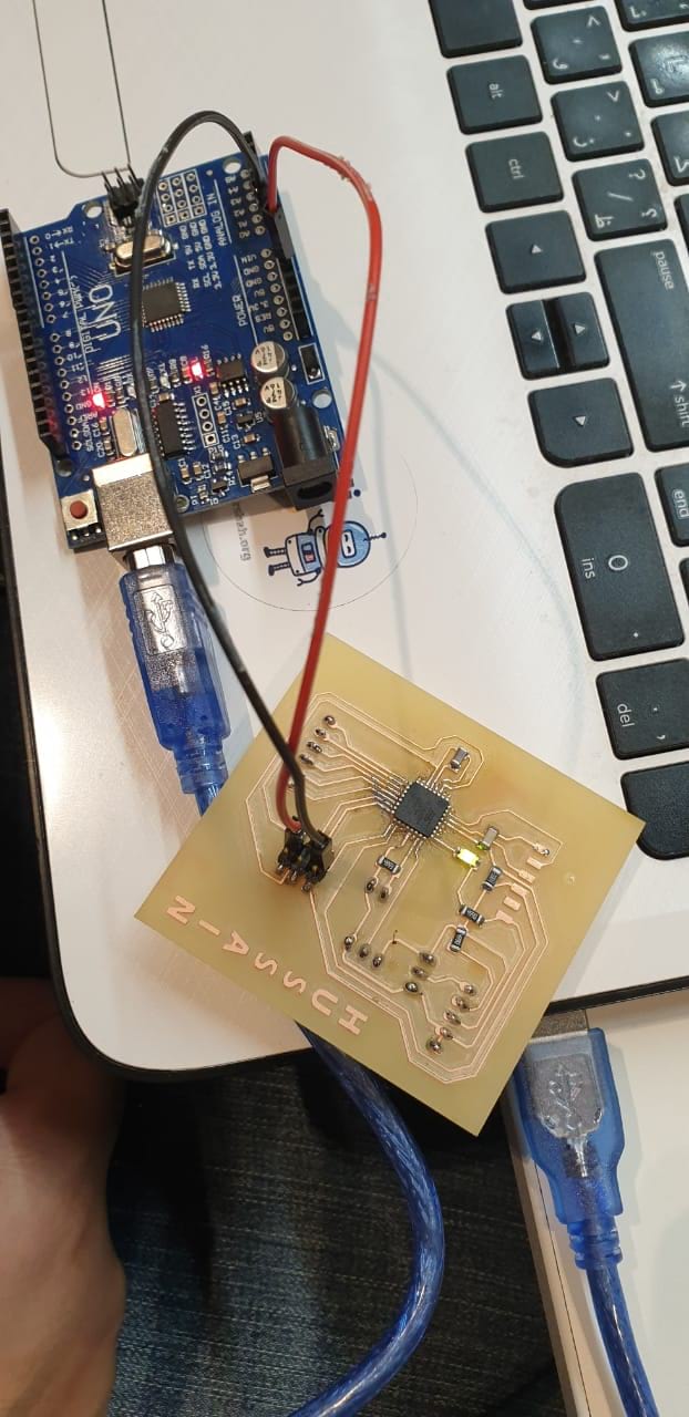
and then soldered the components

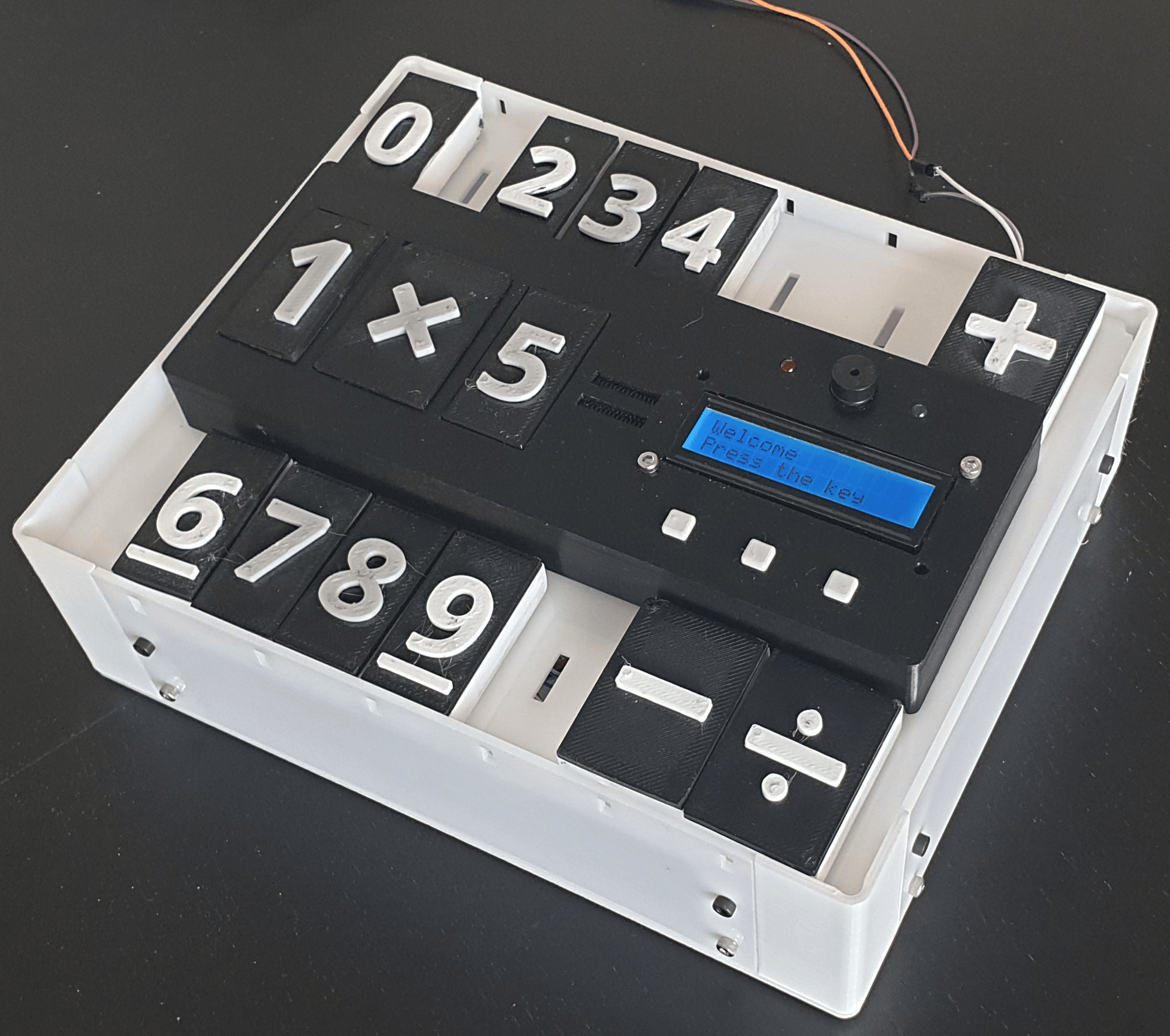
and this was the final Result.
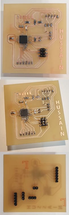
In this image is the explanation that how each number has a different the "numbers that include two digits each (4 bits each)" that the board read number as also the operations as I mentioned at the begning of documentation
_____________________________________________________________________________________________________
Testing and Programming
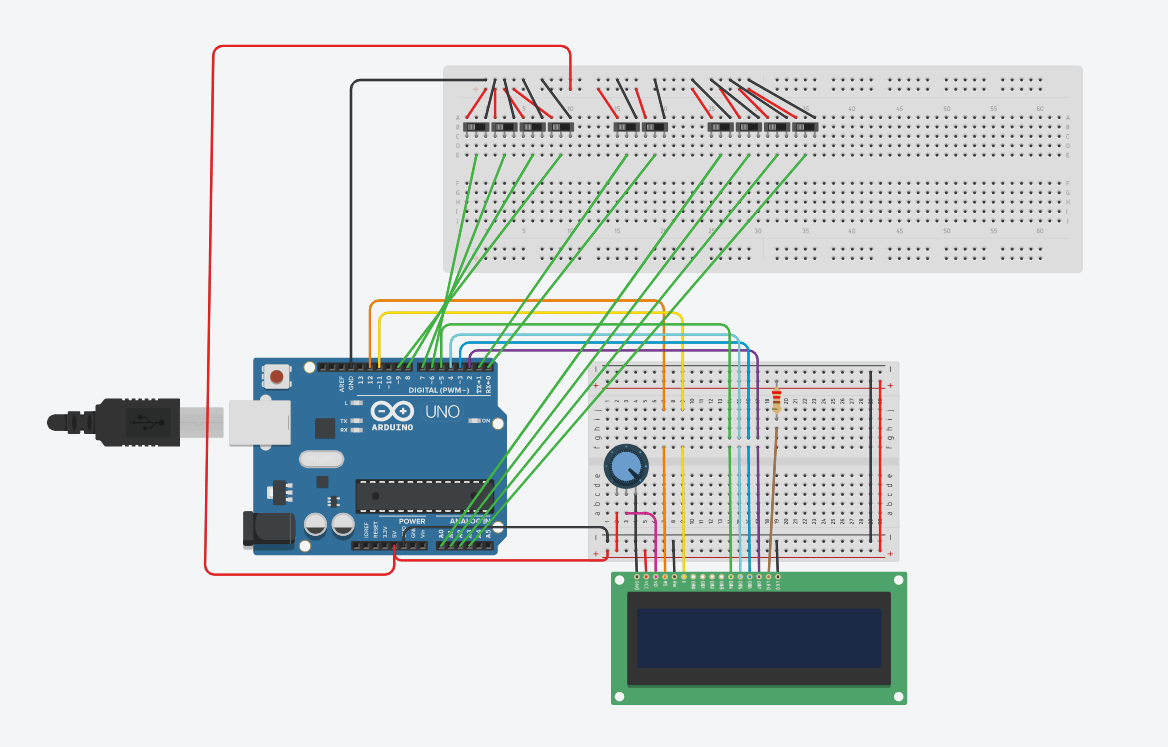
Now, to simulate the operation of my board, I used thinkercad, and simulated by numbers by using sliding switches.
After checking that the logic of my program was working, I then started to do the connections using my board and testing for everything to work. I program by board using another arduino, and then uploaded the code which I will explain next.
I begin my code by defining the pins I’m going to use.
                        #define op1 11
  #define op0 A2
  #define x3 A5
  #define x2 A4
  #define x1 A3
  #define x0 A1
  #define y3 4
  #define y2 3
  #define y1 2
  #define y0 A0
  #define sw1 0
  #define sw2 1
and then define which pins are going to be used for the LCD display.
                      // include the library code:

#include <LiquidCrystal.h>
const int rs = 5, en = 6, d4 = 7, d5 = 8, d6 = 9, d7 = 10;
LiquidCrystal lcd(rs, en, d4, d5, d6, d7);

// initialize the library with the numbers of the interface pins
Then, I Initialize my variables:
                        char operation_sym[4] = { '+', '-', '*', '/' };
  int n1 =0;
  int n2 =0;
  int operation=0;
  int ans, r_ans;
and in the Void Setup, I define the pin modes for the pins I’m going to use, and initialize my LCD .
                      void setup() {  //Serial.begin(9600);
    pinMode(op1, INPUT_PULLUP);     //For operation
    pinMode(op0, INPUT_PULLUP);     //For operation
    pinMode(x3,  INPUT_PULLUP);     //For number 1
    pinMode(x2,  INPUT_PULLUP);     //For number 1
    pinMode(x1,  INPUT_PULLUP);     //For number 1
    pinMode(x0,  INPUT_PULLUP);     //For number 1
    pinMode(y3,  INPUT_PULLUP);     //For number 2
    pinMode(y2,  INPUT_PULLUP);     //For number 2
    pinMode(y1,  INPUT_PULLUP);     //For number 2
    pinMode(y0,  INPUT_PULLUP);     //For number 2
    pinMode(sw1, INPUT);
    pinMode(sw2, INPUT);
    pinMode(12, OUTPUT); //For number  2
    // set up the LCD's number of  columns and rows:
    lcd.begin(16, 2);
    //randomSeed(analogRead(0));
  }
Then, in the Void Loop, I start by a welcome message and wait from an input of the sw1 or sw2
                        lcd.clear();  lcd.clear();
  lcd.print("Welcome");
  lcd.setCursor(0, 1);
  lcd.print("Press the  key");
  while ( digitalRead(sw1)==0  && digitalRead(sw2)==0 ); // Wait for a key
If the pushbutton 1 is pressed, it means its calculator mode, so I need to check the inputs x3,x2,x1, and x0 to determine which number is placed in the first slot, and using the y2,y3,y1 and y0, I identify which number was placed in slot 2. I also check for the operation, which will be a digital input op1 and op2, and depending on the operation selected, I call the method to calculate to find the answer and print it in the screen.
                      //CALCULATE THE OPERATION DEPENDING ON THE INPUT  0 AND 1. 00=/ 01=* 10=- and 11=+
 operation  =  !(digitalRead(op1))<<1 ;
    operation +=  !(digitalRead(op0))<<0 ;  //CALCULATE NUMBER 1 DEPENDING ON inputs  6,7,8,9
    n1=   !(digitalRead(x3))<<3 ;
    n1+= !(digitalRead(x2))<<2 ;
    n1+= !(digitalRead(x1))<<1 ;
    n1+= !(digitalRead(x0))<<0 ;
    if(n1==10)
      n1=0;
       n2=  !(digitalRead(y3))<<3 ;
    n2+= !(digitalRead(y2))<<2 ;
    n2+= !(digitalRead(y1))<<1 ;
    n2+= !(digitalRead(y0))<<0 ;
    if(n2==10)
      n2=0;
       lcd.setCursor(0,  1);\
    lcd.print(n1);
    if (operation == 0){  lcd.print("+");} else
    if (operation == 1){  lcd.print("-");} else
    if (operation == 2){  lcd.print("*");} else
    if (operation == 3){  lcd.print("/");}
    lcd.print(n2);
    lcd.print("=");
    ans = calculate(n1,n2,operation);
    lcd.print(ans);
    delay(400);
    }
Method Calculate just returns the answer of the operation, which could be add, subtract, multiply or divide, depending on the inputs for operation,
                      //CALCULATE THE OPERATION DEPENDING ON THE INPUT  0 AND 1. 00=/ 01=* 10=- and 11=+
  int calculate ( int x, int y, int operate)
  {
    if (operate == 0){
        return x+y  ;
      }
      else if (operate ==  1){
        return x-y  ;
      }
    else if (operate == 2){
        return x*y  ;
      }
      else if (operate ==  3){
        return x/y  ;
      }
  }
If the push button 2 is pressed, I call task 2,
                      else if ( digitalRead(sw2)==1 )
    {
    task2();
      lcd.setCursor(4, 0);
      lcd.print("Good  Job    ");
      digitalWrite(12,HIGH);
      delay(1500);
      digitalWrite(12, LOW);
    }
  }
In task 2, I will display a random operation in the screen, and the student needs to select the correct answer and place it in the slot. For this, I generate a random operation, from 0to4, and 2 random numbers from 0 to 9. Internally, I calculate the answer, and then wait for the student to place the tile of the answer he thinks is true. I wait until the correct answer is placed in order to exit the while, and the turn on the LEDs and buzzer, meaning they got the right answer.
                          void task2()
    {
    lcd.clear();
    lcd.print("Solve Me");
    operation = random(3);
    n1 = random(9);
    n2 = random(9);
    r_ans =  calculate(n1,n2,operation);
    lcd.setCursor(3, 1);
    lcd.print("=");
    lcd.print(r_ans);
    while ( true )
    {
      read_();
      if(n1!=0) // check if  there is a number
      {
        if(n1==10)
          n1=0;
        lcd.setCursor(0,  1);
        lcd.print(n1);
      }
      if(n2!=0)
      {
        if(n2==10)
          n2=0;      lcd.setCursor(2, 1);
        lcd.print(n2);
    }
      lcd.setCursor(1, 1);
      lcd.print(operation_sym[operation]);
    ans =  calculate(n1,n2,operation);
      if (ans == r_ans)
      {
        return;
      }
    }
  }
The video passes the process that the final project took to get real
Since I was thinking on the final project, my goal has been to be an open source project that the company can use in its projects within the digital fabrication education programs. Through our work in the field of education, especially with hight scool level, it will be appropriate to present the project to present in thelessons that students can learn in various fields related to digital fabrication. I also hope this project is an assistant and a good start for many people so they can develop their skills and develop the project for anyone who has been.
I will work on developing the project in order to have a variety of mathematics programs. As I mentioned that the final project is an open source will be internationally licensed without any commercial profit through a creative commons website, specifically is "attribution-noncommercial-shareAlike 4.0 international public license".
To open or download file