3. Computer aided design
Assignment
Model (raster, vector, 2D, 3D, render, animate, simulate, …) a possible final project, and post it on your class page
| Documentation |
|---|
| 1. Autocad_File.dxf |
| 2. Finger_joint_Box.svg |
This week, I’m going to work on modeling my boat and try to think of everything it has to contain. I’ll try to challenge myself to be as clean as posible in my design.
3.1 CAD Modeling
I have already a background in 2D and 3D CAD modeling but I’ve learnt from the class few ways to do 3d modeling :
- Constructive Solid Geometry (use constraints to make 3d models)
- Generative Design (Automated ways to do to 3D modeling using functions)
- Functional Representation modeling (CAD using graph to relate objects)
Also, I’ve understood that a functionality that I have to work with is parametric design.
Before going deepeer into making the boat, I’ve decided to experiment diferent softwares to understand the different possibilities each one can afford.
2D CAD modeling
There are two ways to make 2D CAD modeling :
- Raster (good to explain a concept)
- Vector (better to actually use the file for digital fabrication)
I’ll mostly focus on vector softwares as it’s going to be the most useful for me.
Inkscape
Inkscape is a free software where you can create vector 2D models. It’s a very powerful tool to make files for the laser cutter.
It’s relatively easy to use it as the interface is similar to many drawing softwares :
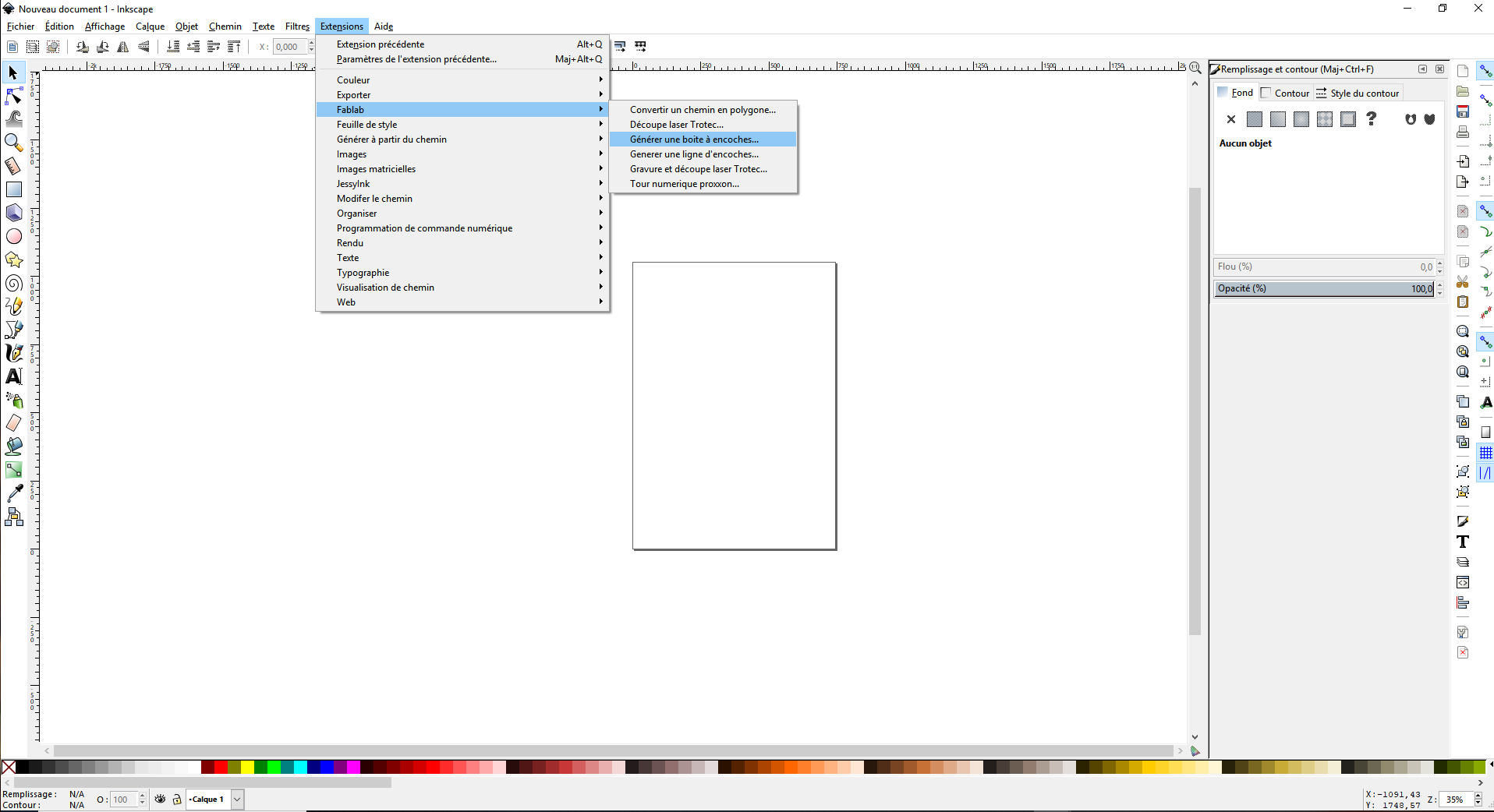
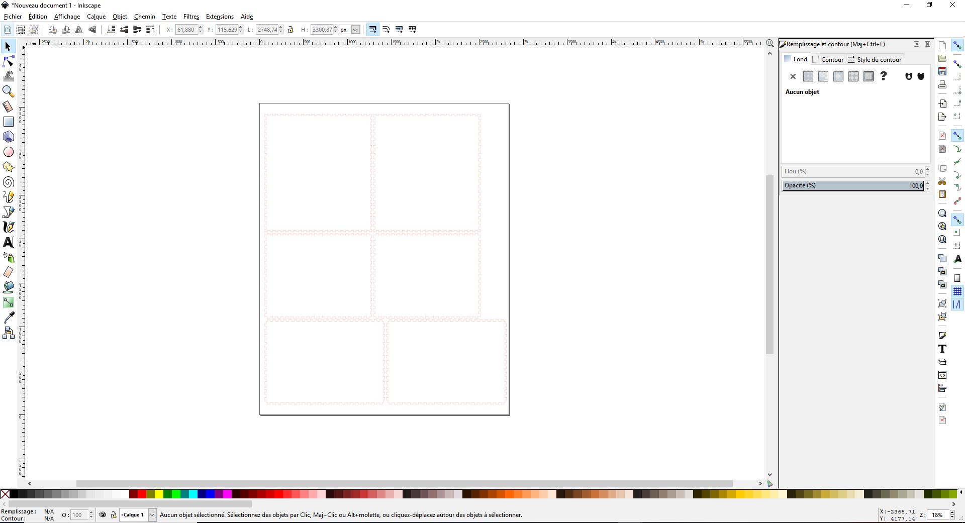
The cool thing about this software is that you can add plugins. A cool one is the fablab extension where you can for example generate parametric finger joints boxes.
On Inkscape website we can find well done tutorials to get to know more about how to use the software.
My idea of this tool :
| Easilly accessible | to put an exact dimension can be tricky |
| Support parametric design |
Autocad
Autocad is a software you can use to create 2D models (3D models as well but I don’t use it). It’s a very powerful tool to make files for the laser cutter.
It’s a software used a lot in the architecture field to make drawing of houses.
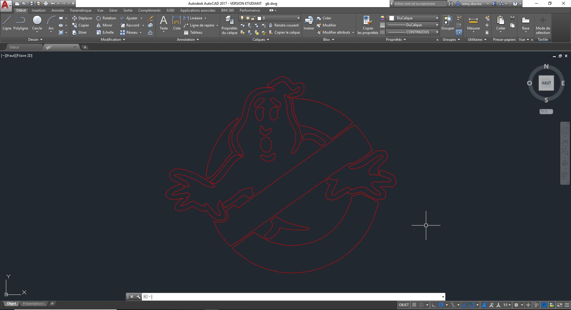
The cool thing about this software is that you can work with layers (like in photoshop) where you can asset some parameters. It’s useful for the laser cutter to make a difference between a line to cut or to engrave.
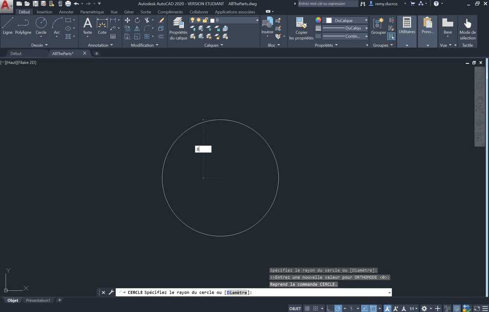
To draw using autocad we need to use the drawing elements of the software.
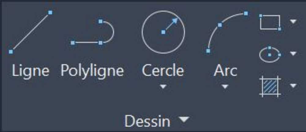
The particularity of this software is that you have to put dimensions as you draw (unlike solidworks for example where you can draw a circle then use a cotation tool to put the correct dimensions).
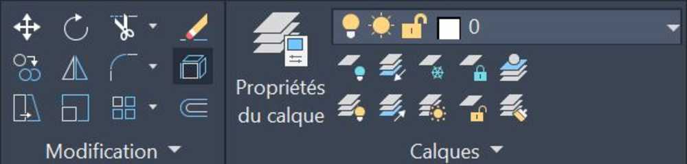
Few other tools I often use are :
- The Layer tool to give assets to the line I draw (we can change colors and thickness of each line to asset a job to the lasercutter like raster or vector).
- The Decompose tool to decompose dxf files we import from other softwares (like inkscape for example).
- The Delete all doubles tools to remove all the lines stacked on top of eachother. This tool is useful to avoid the laser cutter to cut multiple times on a line.
To get to know more about how to use this software there are great tutorials online.
My idea of this tool :
| Easily accessible | format issues |
3D CAD modeling
OpenScad
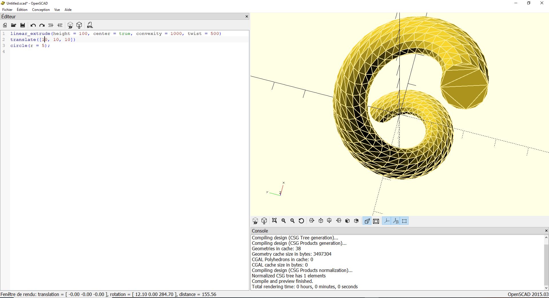
Openscad is an open source software where you can create 3D models by making line codes.
I’ve been through the OpenScad user manuel and also through the OpenScad cheat sheet to make some interesting shapes. This shapes are more or less complex.
 |
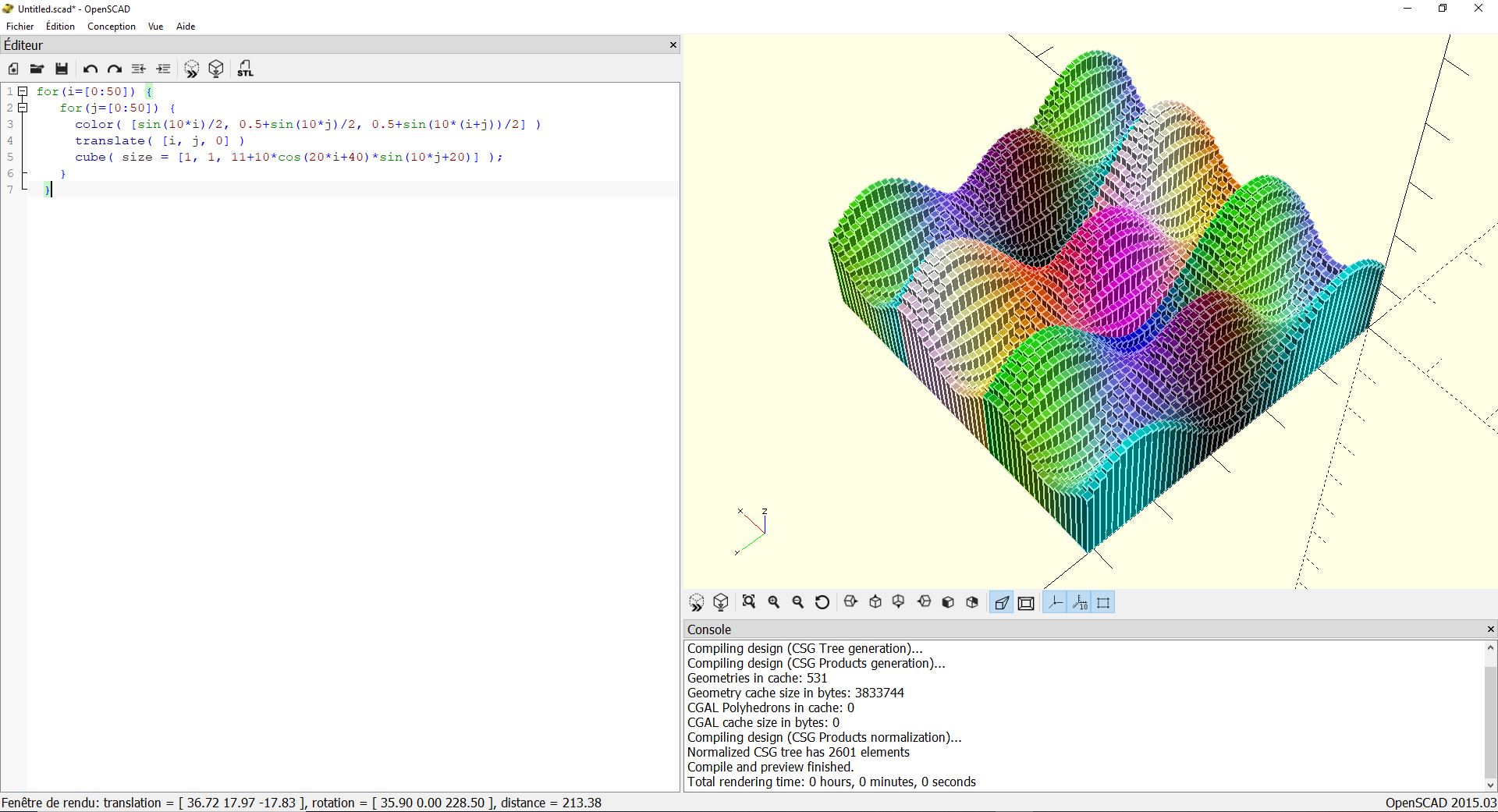 |
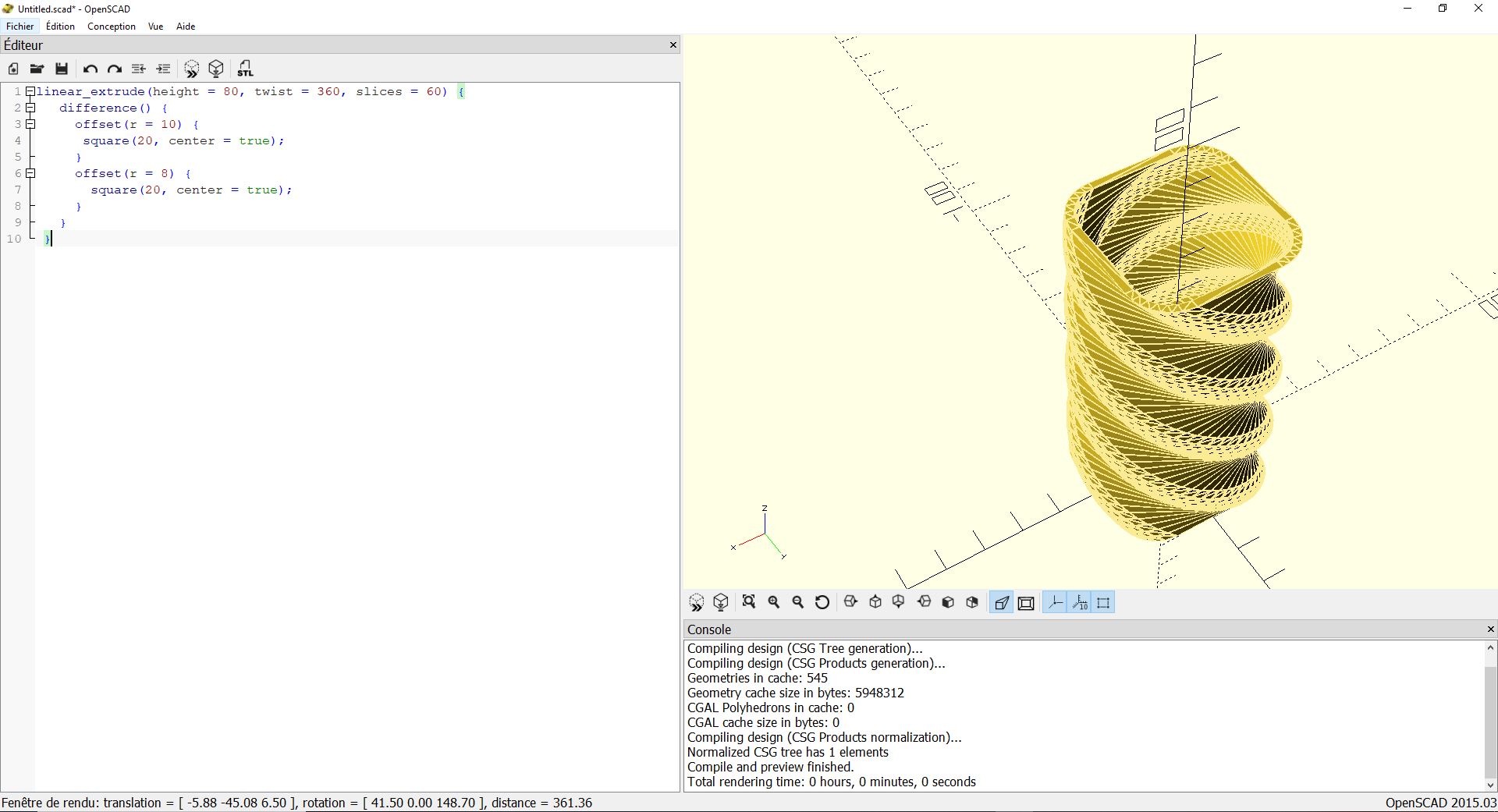 |
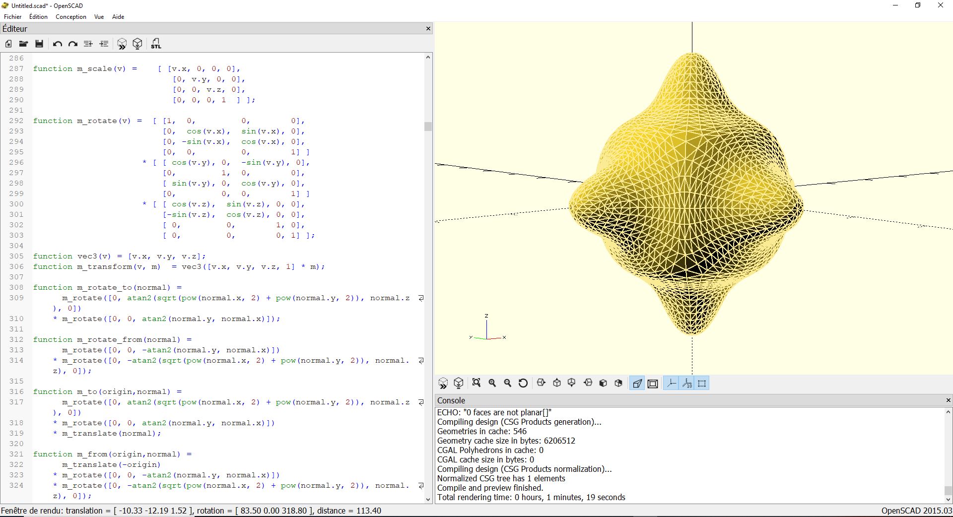 |
The last one is a quite complex one (more than 1000 lines) based on Conway mathematical experiments. It took few minutes to compile.
NOTE : There is an online version of OpenScad called OpenJScad
My idea of this tool :
| You can make complex design | The interface is not very user friendly |
| You can make parametric design | The coding part is yet another thing to learn |
Mods
Mods is a web interface developped by MIT-CBA where you can create 3D models using linked graphs.
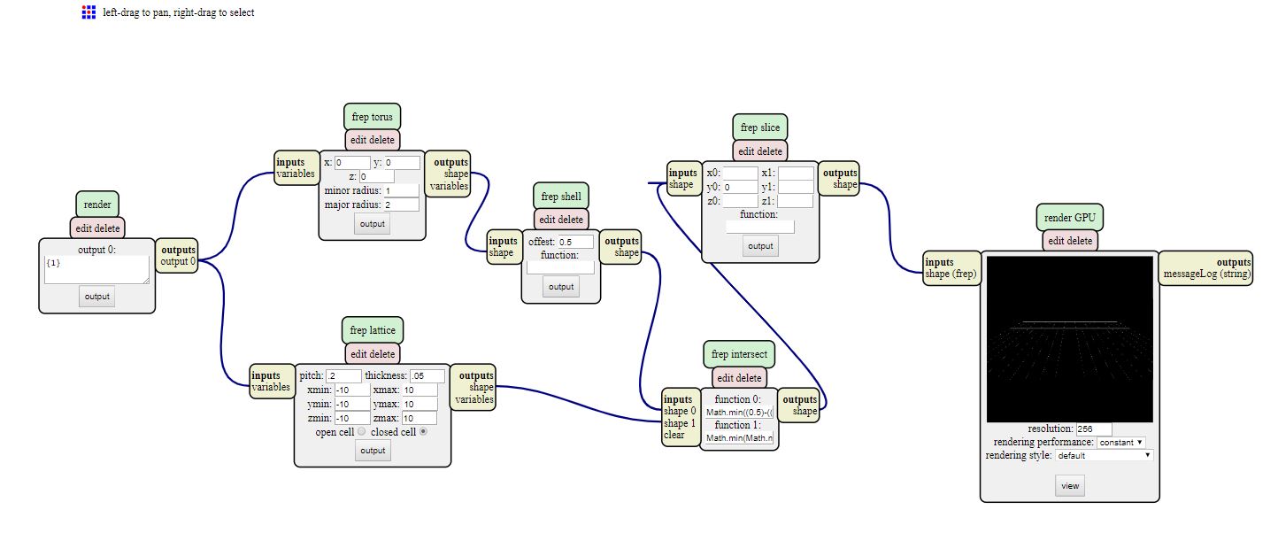
I was very impressed by Neil’s presentation but I didn’t managed to make it work properly. I think I was missing some key inputs to really get into it.
It’s a really cool tool but I don’t think, I’ll be using it for my project. I’ll go deeper into the online documentation to learn how to use it.
Fusion 360
Fusion 360 is a CAD software developped by Autodesk.
I have a bit of experience with CAD modeling using Solidworks and Catia. I wanted to go for a software to keep doing my projects and I found Fusion 360 very handy.
I’ve already done some projects using Fusion 360 so I’m familiar with the environnement
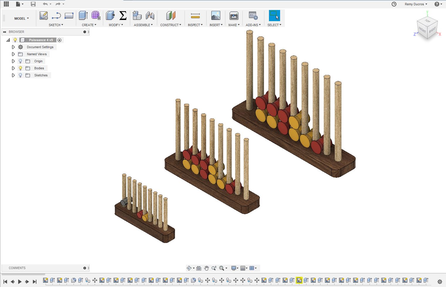
Here is a design of a bordorless connect four, I’ve made.
My idea of this tool :
| Easily accessible | Not open source |
| Cloud friendly | Need an internet connection to work properly |
| Complete | |
| Well integrated |
For my Fabacademy final project, I’ll work mostly with Fusion 360
3.2 The design of the boat
I’m not a naval engineer and the shape of the boat is free, so I first went through images to see the different types of boats that exist.
I’ve seen a lot of different possibilities online.
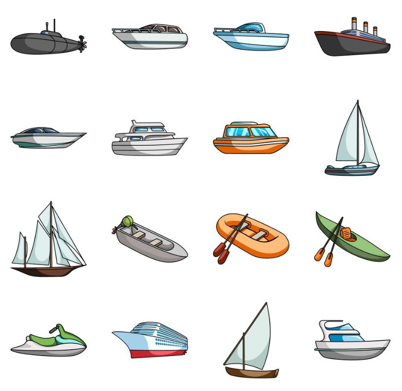
However I didn’t find a shape not to simple yet not to complex to do the CAD model of.
Finally I saw on a table in the fablab a 3D_Benchy. I 3D print a lot this model when I want to test a 3D printer.
I thought it would be a good idea to get my inspiration from this well known model, so I’ve printed one to have it in my hand to better understand the design of it.
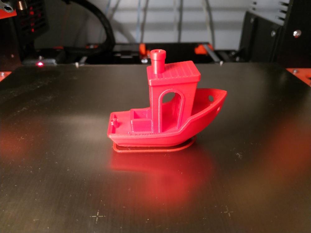
I’ve decided to go for this design as well because I’ve seen many videos of it floating, even someone did a sRC model of it.
So let’s make my own version of the 3D benchy (but much bigger).
Parametric design in Fusion 360
For this projet I wanted to challenge myself and do something I’ve never done before : Parametric Design in Fusion 360.
Thanks to the Autodesk knowledge page and this page about best practices, I was able to identify some guidelines:
- All my sketchs must be fully constraint
- It’s sometimes better to use some constraints between sketchs elements rather than dimensions
- I can make a parameter linked with another one
- …MORE TO COME
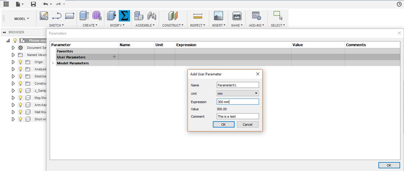
To use Parameters in my design in Fusion 360, I have to
- go to Model workspace
- then go down to Modify
- and finally Change parameters.
Then I have to add a User Parameter, give it a name, a value (you can change later), a comment. Later when I’ll put dimensions in my sketch, instead of putting a value, I’ll just put the parameter name and it will take the value you’ve pre-set.
Overall, I’ve tried to use parameters and constraints as much as possible, to make this boat easy to modify if needed.
Yet I have to test the limits of each parameter and modify some sketchs if needed.
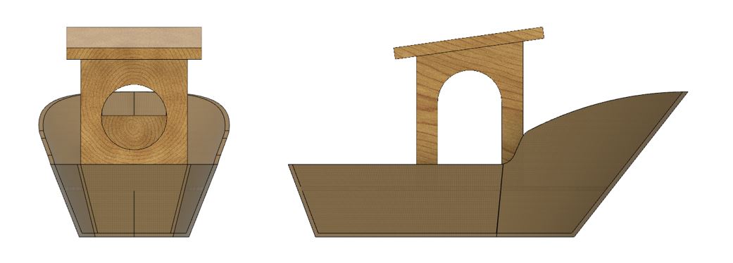
The main design
Here is a photo of the main design of my boat :
Here is a video showing the making process of the basic shape :
Here’s a 3D model of my basic design :
Following this link, you’ll find an updated model of my boat.
The boat is divided into four parts :
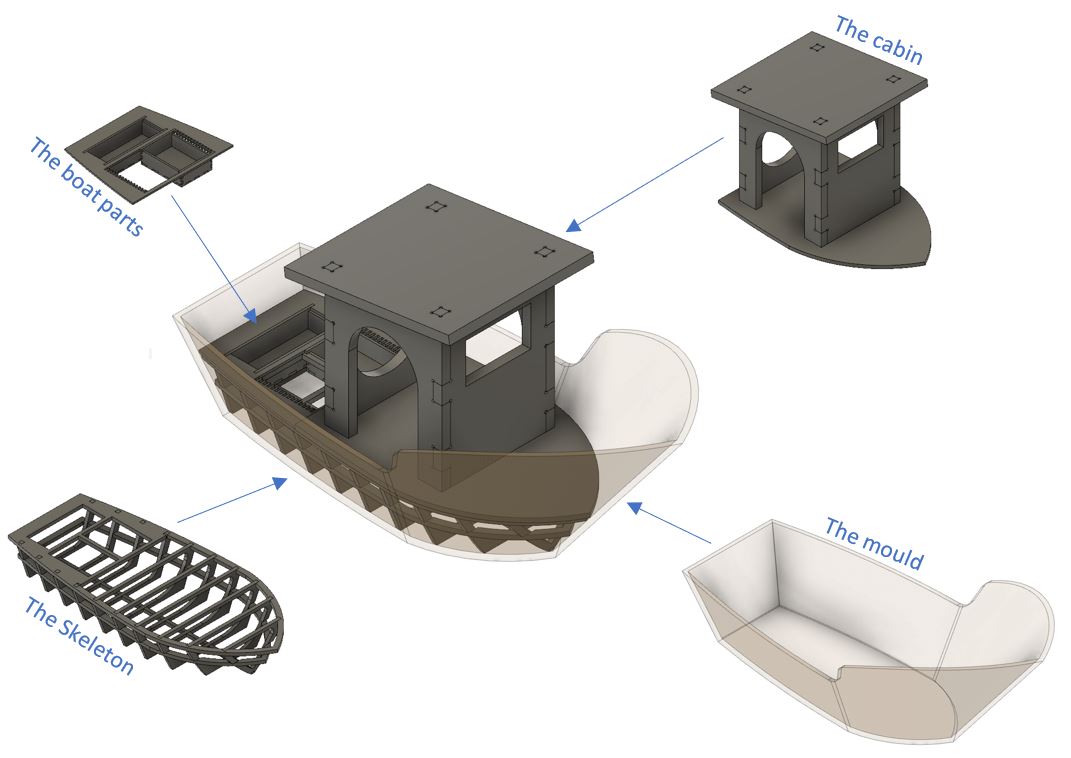
The mould
The design
For this part I’ve set a few parameters :
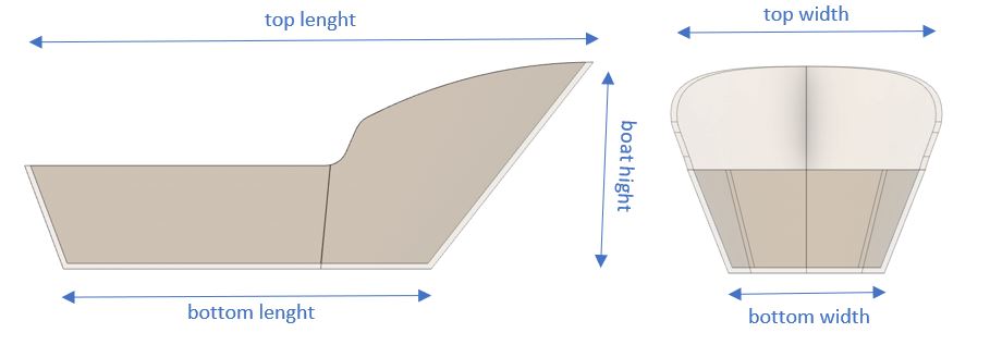
NOTE : The bottom width is function of the bottom Lenght and the top width is function of the top Lenght.
Each parameter is a User Parameter I have set in Fusion 360.
The making process
I want to make a negative mould of this boat using the CNC machine and blue foam. Then I’ll be able to make a positif model using composite, or natural material (I’ll have to do some tests).
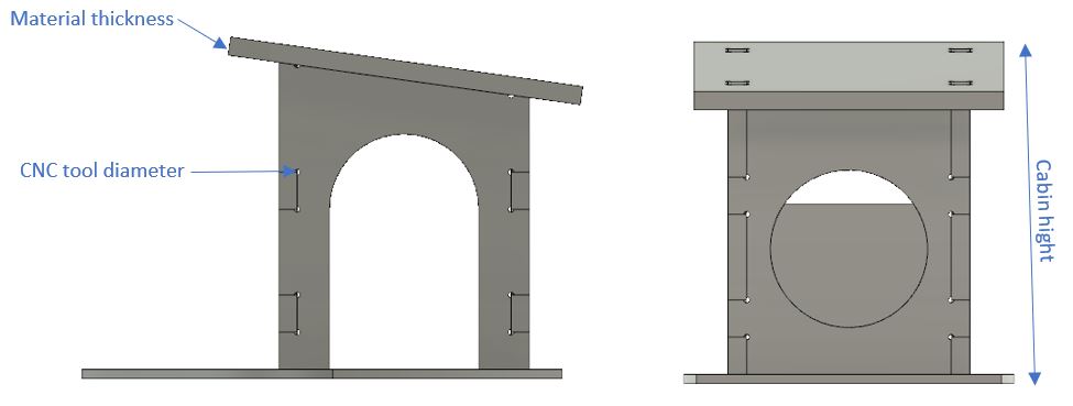
The cabin
The design
For this part I’ve set a few parameters :
The making process
The base of this part is going to be laser cut in a 10mm thick beech plank. Everything else is going to be cut using thicker beech plank in the CNC milling machine. As I put as parameters the thickness of the wood and the diameter of the tool, it should be easy to modify the CAD model to match our equipement if needed.
The skeleton
The design
This part is the wooden part of the boat which will give strengh to the overall model.
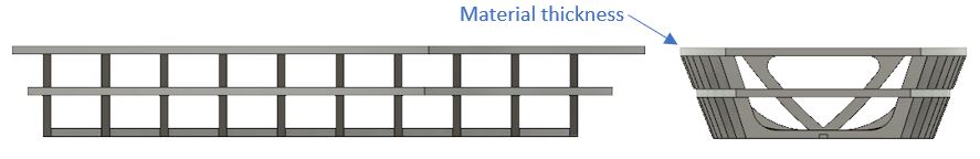
The only parameter I have here is the material thickness. The whole design is fully constrainted and the shape will adjust depending on the material thickness.
I had to adjust the automatic design in order to make the part using the laser cutter.
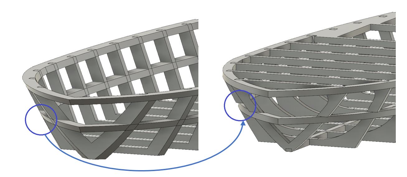
I think this shape is a bit completed to be fully automatic using parameters. Yet the base is here and I think only few updates will be necessary if we want to change the dimension of the boat.
The making process
I’ll make the whole skeleton using 10mm beech plank in the laser cutter.
The boat parts
The design
This part of the boat is where I’m going to put all the electronics. As the boat is going to be studied, I want it to be modular and easily dismountable.
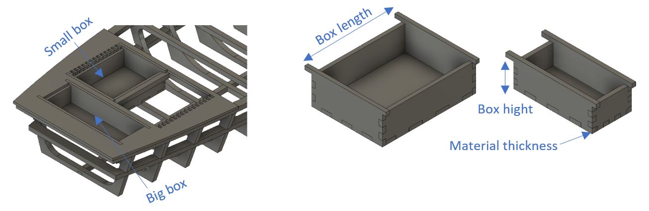
The holes where I put the boxes are constrainted by the shape of the boat.
There are three slots to put modular boxes. Using the material thickness, the length and the hight of the box I’m able to generate automatic finger joints boxes. The size of those boxes will depend on what I’m going to use it for.
NOTE : The width of the box is fixed by the shape of the holes so it’s not a parameter.
The making process
I’ll make everything using 5mm thick beech plank in the laser cutter. I’ll also use a 5mm transparent PMMA sheet to protect everything yet having a look a it.
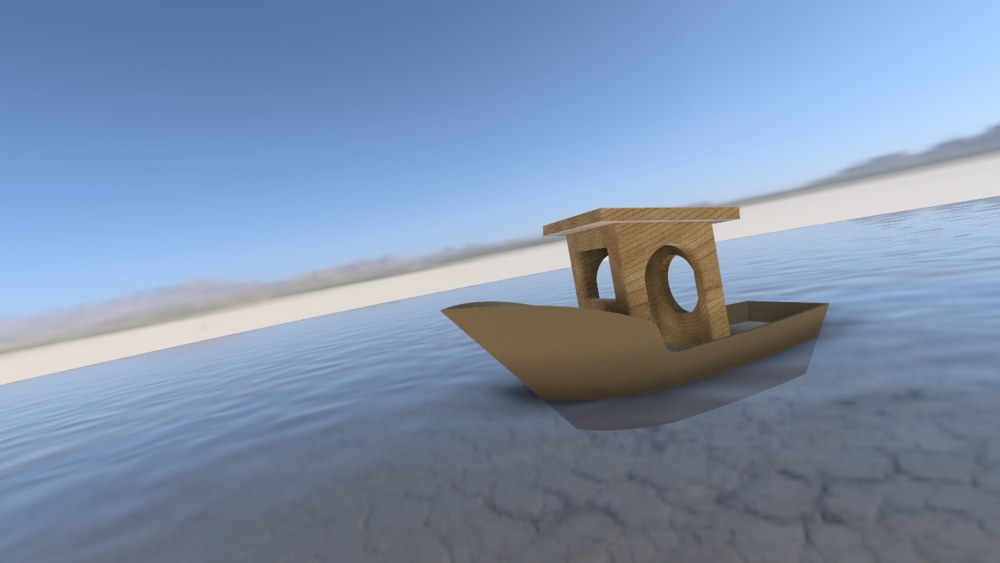
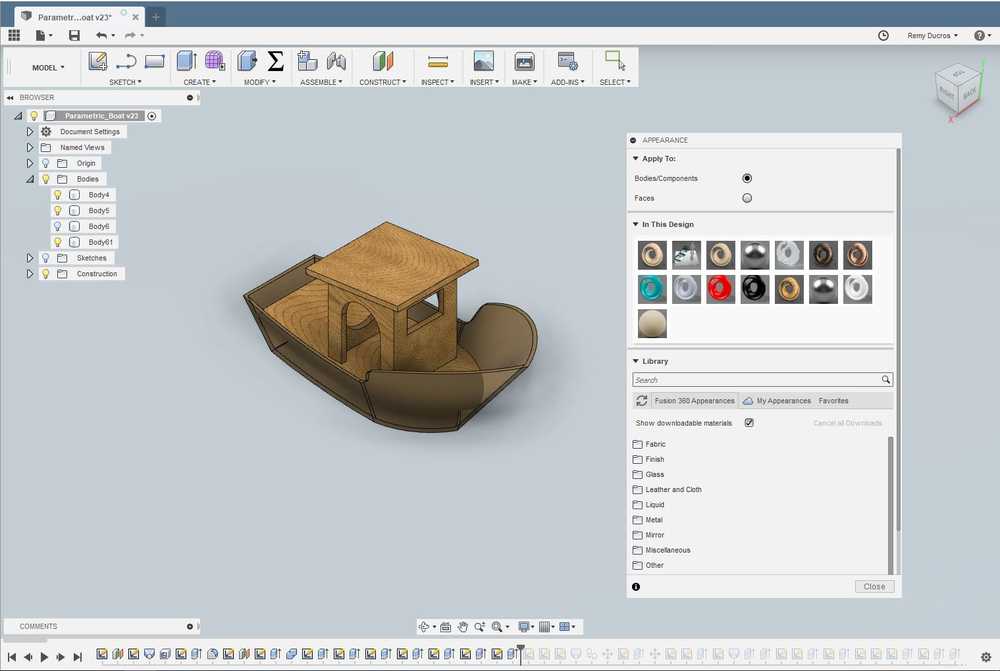
3.3 Rendering
In the model section in fusion 360 by pressing a an apparence windows shows up where you can assign a material to each body. To make the water here I created a body and gave it the apparence of the clear water. In the rendering section you can tune the lights and the baground to put your design in a “real life” environnement.
 |
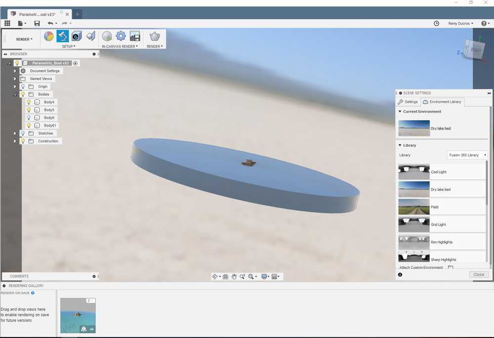 |
After tuning the lights and trying to find a nice angle I saved the following screenshot.

Ce(tte) œuvre est mise à disposition selon les termes de la Licence Creative Commons Attribution - Pas d’Utilisation Commerciale - Partage dans les Mêmes Conditions 4.0 International.