4. Computer controlled cutting
Group assignment:
Characterize your lasercutter, making test part(s) that vary cutting settings and dimensions
Individual assignment:
Cut something on the vinylcutter design, lasercut, and document a parametric press-fit construction kit, accounting for the lasercutter kerf, which can be assembled in multiple ways
| Documentation | |
|---|---|
| 1. Kerf_Test.dxf | 2. Kerf_Test.f3d |
| 3. PLA_Test_Part.STL | 4. PressFitKit.dxf |
| 5. PressFitKit.f3d | 6. Final_Project.dxf |
This week, I’m going to make a pressfit kit in cardboard using parametric design in Fusion 360 and a lasercutter. I’m also going to learn how to use a vinylcutter and cut something with it.
4.1 Group assignement
As a group assignement we add to characterize our lasercutter.
We have two lasercutters at digiscope:
- An Epilog Fusion M2 (CO2 and Fiber)
- An Epilog mini 40W (CO2)
The Epilog mini was not operational so we focused on the Epilog Fusion M2 for our tests.
The operations to use the lasercutter
We need a 2D vectorial drawing.
To draw it we can use softwares like Inkscape or Autocad. I use an add-in in Fusion 360 which late you select a face, then it creates contours and save them as DXF.
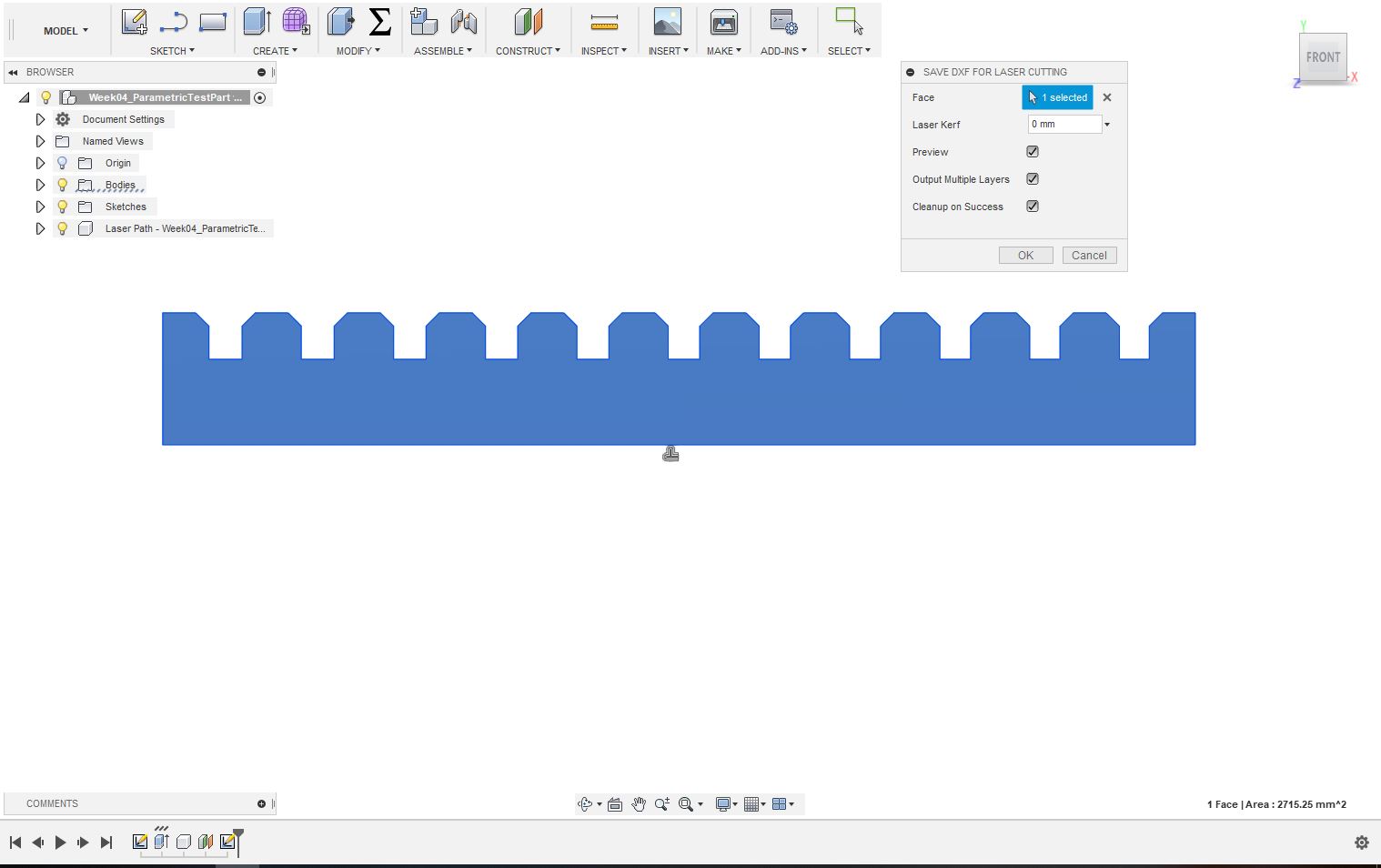
We can even offset the contours according to our kerf. As we are trying to characterize it I kept the value as zero to have the exact contour.
Making the file ready for the lasercutter
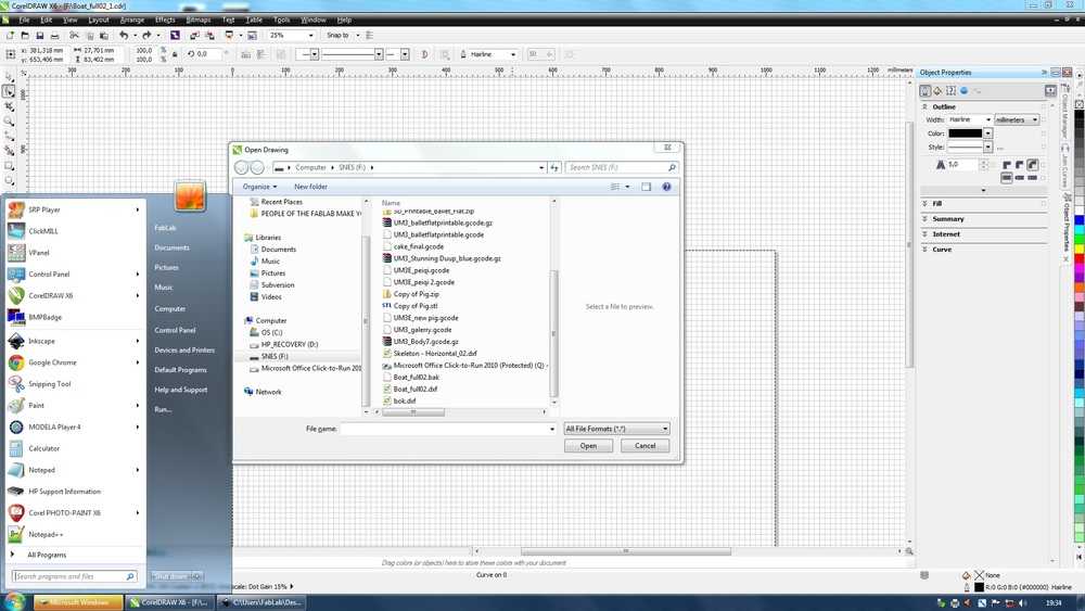
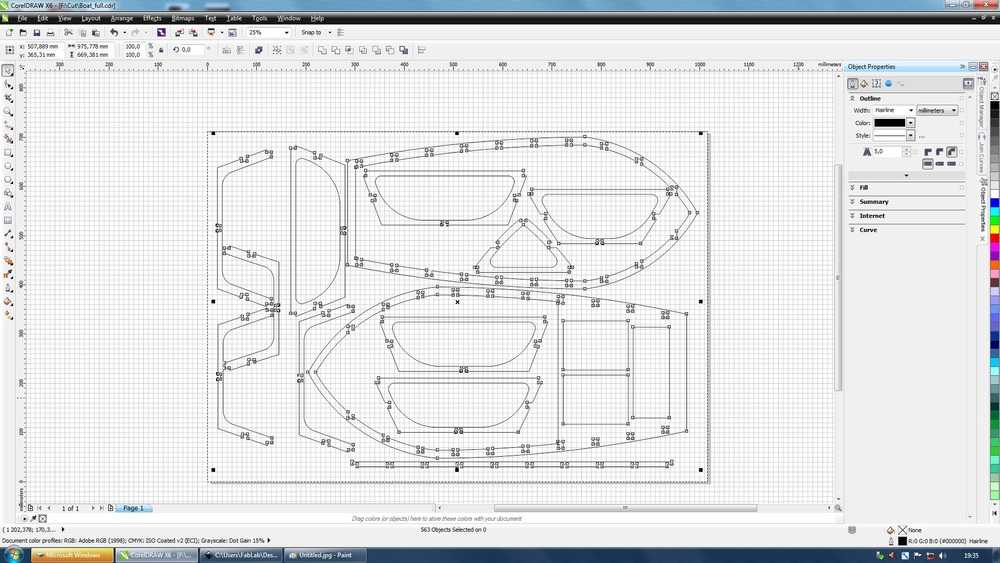
We used the software CorelDraw to make the machine understand what it has to do. First we opened the software. The default page shows the maximum area we can use in the machine. We then import our dxf file from Fusion autodesk360.
 |
 |
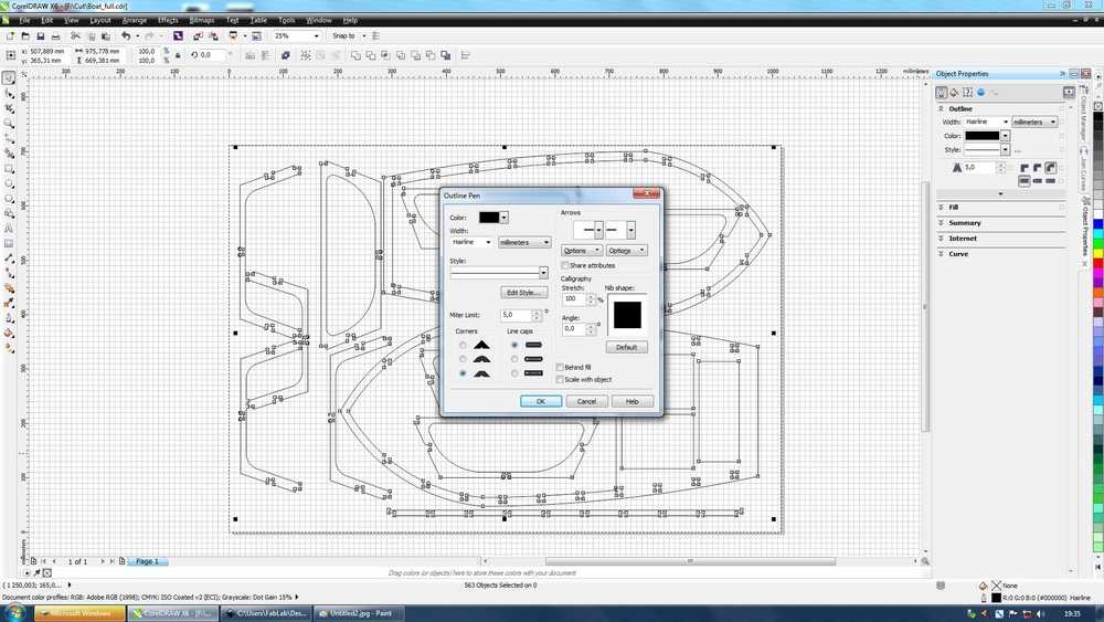
In order for the machine to cut the parts we need to make sure all the lines we want to cut have the Hairline thickness. Overwise the machine won’t cut anything.
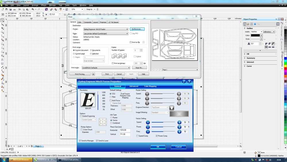
Then we print and select the machine. It opens the lasercutter driver. It’s where we put the machine settings according to the job we want it to do (raster or vector) and it’s also where we select the source we want to use (CO2 or Fiber).
 |
 |
After pressing Aplly then Print the job goes into the machine and we can then work from there.
Using the machine
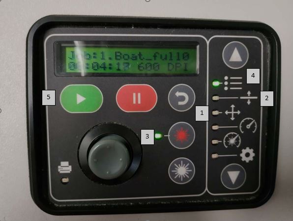
The machine has a control pannel where we have different commands :
- 1.Manually move the head and set the XY origin
- 2.Manually move the bed and set the Z origin
- 3.Switch on/off the pointer
- 4.See a job details
- 5.Select the job
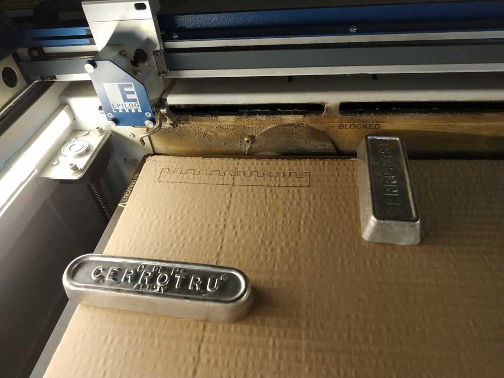
We have to put the material in the machine and make sure it’s flat. If not we can use weight (where the laser won’t cut) to maintain it flat.
We use the control pannel to make the XY origin using the pointer. We then use a device to set the Z origin.
Once everything is set, we switch the vent, and the supressor. The vent is here to take all the fumes away, and the supressor is here to blow air on the surface of the material to prevent flames.
After evertyhing is done, we can wait a bit for the fumes to be evatuated and take our parts.
 |
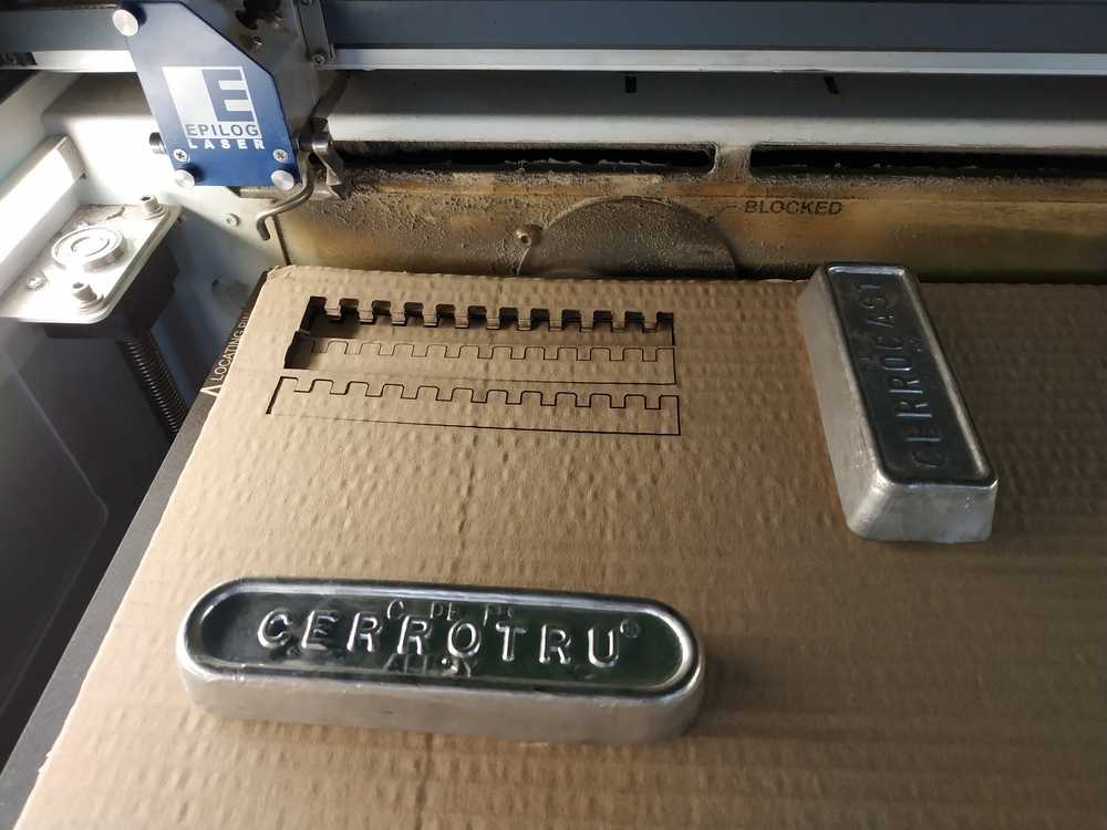 |
We tried the CO2 source to cut lots of different materials and the Fiber source to engrave some PCB on copper.
 |
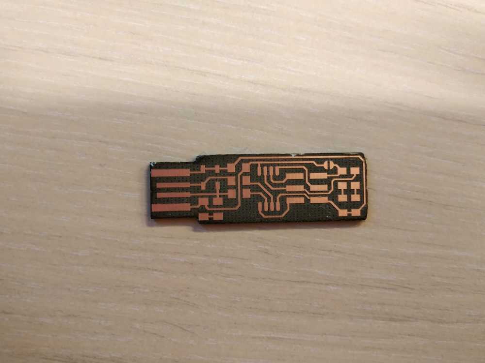 |
I’ll cover our results for the CO2 cutting later in this page and Fiber part in Week05.
Safety
- We must stay next to machine as we use it (to prevent fire)
- We must not use materials with chlorine like PVC (to prevent toxic fumes)
- We must not use refleting material (like metal) with the CO2 source (to prevent damaging the tube)
Identifying the kerf of our lasercutter
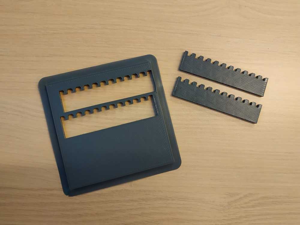
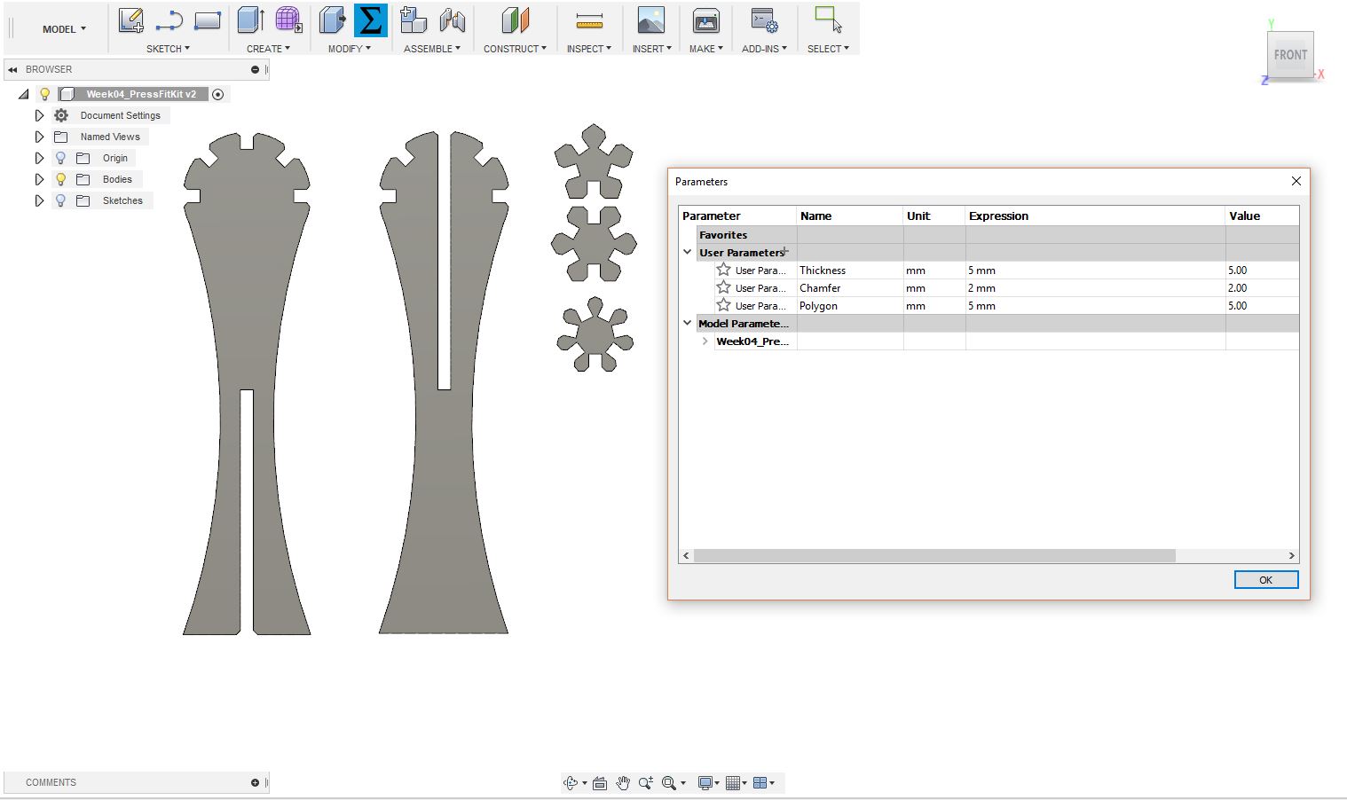
Making the parametric test part
We first designed in Fusion 360 a parametric part to test the kerf of the lasercutter.
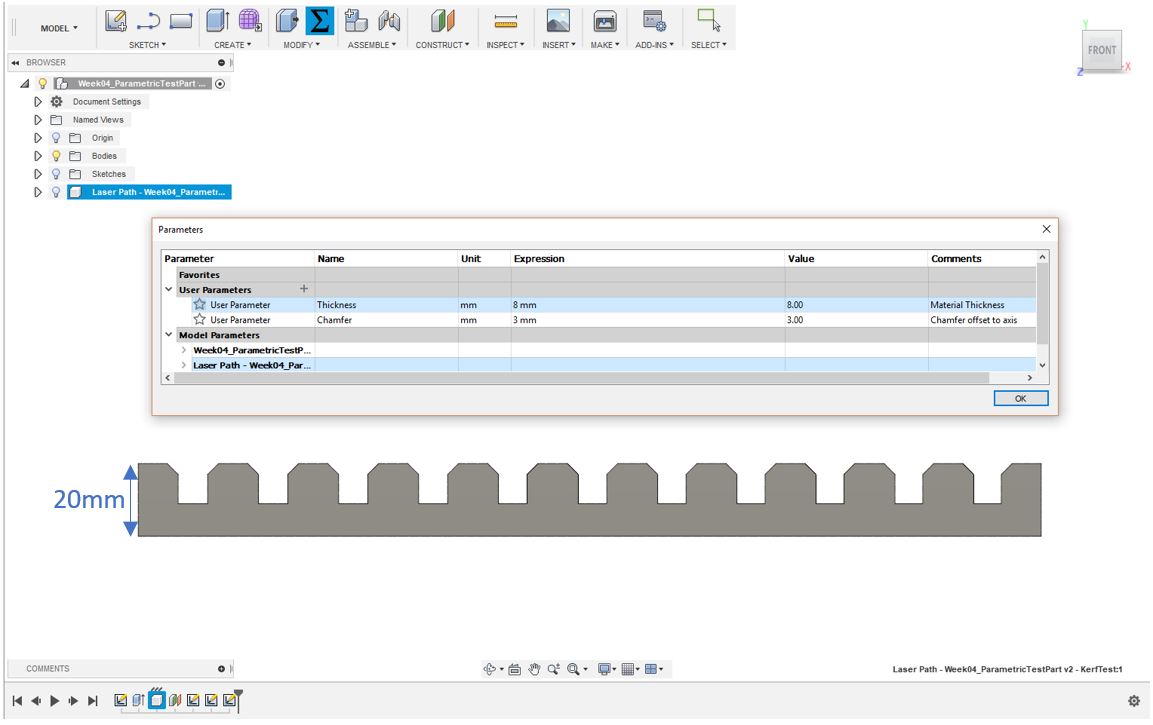
Here we kept the hight of the part always the same (20 mm) so we can measure it after each cut to check how much material we lose each time.
The junction width is function of the thickness of the material. Each time we duplicate it on the right the width is reduce by 0.05mm. This way, using two parts we will be able to see when we have the best fit and identify the kerf of the lasercutter.
We can also adjust the size of the chamfer using a parameter in Fusion 360.
Testing the cut settings for each material
We decided to select lots of material to test. We also 3D printed a test part to see how we can cut PLA as well.
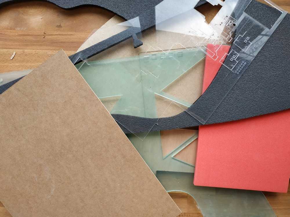 |
 |
For each material we tried different settings to cut it properly. Here are our results :
| Material | Thickness | Speed | Power | Frequency | Passes | Time/pass | Observations |
|---|---|---|---|---|---|---|---|
| Acrylic | 1.4 mm | 5 | 100 | 50 | 1 | 30 s | Cut |
| Acrylic | 3 mm | 5 | 100 | 50 | 1 | 30 s | Cut |
| Acrylic | 5 mm | 6 | 100 | 50 | 2 | 35 s | Cut |
| Acrylic | 5 mm | 2 | 100 | 50 | 1 | 1 mn 30 s | Cut |
| Cardboard | 6 mm | 25 | 30 | 50 | 2 | 20 s | Cut |
| Cardboard | 6 mm | 20 | 30 | 50 | 1 | 19 s | Not cut |
| Cardboard | 6 mm | 15 | 30 | 50 | 1 | 22 s | Not cut |
| Cardboard | 6 mm | 10 | 30 | 50 | 1 | 26 s | Cut |
| Cardboard | 14 mm | 20 | 50 | 50 | 4 | 29 s | Not cut |
| Cardboard | 14 mm | 15 | 50 | 100 | 4 | 39 s | Not cut |
| Cardboard | 14 mm | 15 | 75 | 100 | 4 | 39 s | Not cut |
| Cardboard | 14 mm | 10 | 100 | 100 | 4 | 55 s | Not cut |
| Cardboard | 14 mm | 5 | 100 | 100 | 1 | 1 mn 33 s | /!\ Burn /!| |
| Cardboard | 14 mm | 10 | 70 | 100 | 4 | 55 s | Not cut |
| MDF | 3 mm | 15 | 100 | 50 | 2 | 15 s | Cut |
| MDF | 3 mm | 10 | 100 | 50 | 1 | 18 s | Cut |
| MDF | 5 mm | 8 | 100 | 50 | 2 | 27 s | Cut |
| MDF | 5 mm | 5 | 100 | 50 | 2 | 39 s | Cut |
| MDF | 6 mm | 5 | 100 | 50 | 2 | 46s | Cut but limit |
| MDF | 6 mm | 3 | 100 | 50 | 2 | 57s | Cut |
| Beech wood | 5 mm | 15 | 100 | 50 | 4 | 17 s | Cut |
| Beech wood | 5 mm | 5 | 100 | 50 | 1 | 42 s | Cut |
| Beech wood | 10 mm | 2 | 100 | 50 | 2 | 2 mn 42 s | Cut |
| Beech wood | 10 mm | 3 | 100 | 50 | 2 | 2 mn 48 s | Cut but limit |
| Dense Foam | 5 mm | 50 | 50 | 50 | 1 | 11 s | Not cut |
| Dense Foam | 5 mm | 30 | 50 | 50 | 1 | 14 s | Not cut |
| Dense Foam | 5 mm | 30 | 100 | 50 | 1 | 13 s | Not cut |
| Dense Foam | 5 mm | 20 | 100 | 50 | 1 | 14 s | Cut |
| Dense Foam | 5 mm | 25 | 100 | 50 | 1 | 14 s | Cut but limit |
| Dense Foam | 10 mm | 10 | 100 | 50 | 1 | 39 s | Cut |
| Light Foam | 10 mm | 20 | 100 | 50 | 1 | 40 s | Cut |
| PLA | 3.3 mm | 10 | 100 | 50 | 2 | 15s | Cut |
| PLA | 3.3 mm | 7 | 100 | 50 | 2 | 18s | Cut |
NOTE : We suprisely didn’t manage to cut trough the 14 mm thick cardboard. I think one explaination could be that the laser isn’t straight so it loses its power has we go deep. Maybe we reached the critical thickness. Also cardboard is a material easily inflammabe so we cannot put much power trying to cut it or it started to burn.
Testing the cut accuracy and the machine kerf
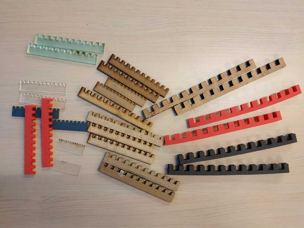
After all these tests we had some parts to work with :
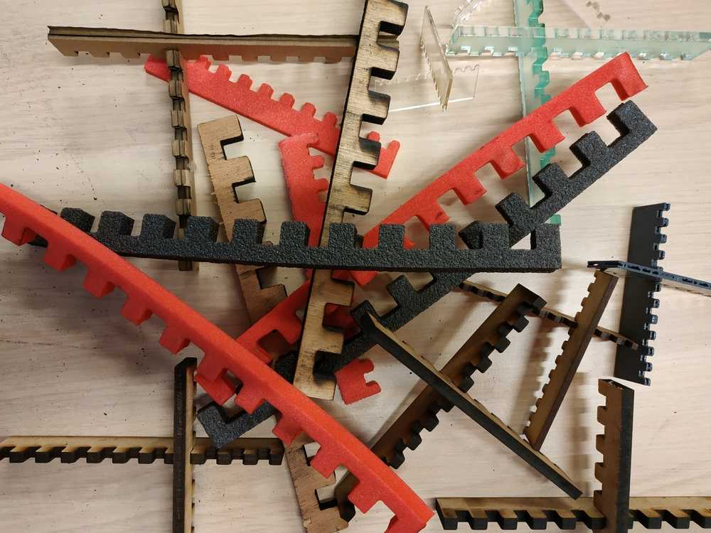
I then measured using a vernier caliper the hight of the parts and check at what dimension the two parts fit better. Here are my results :
| Material | Thickness | Meas01 | Meas02 | Meas03 | Meas04 | Kerf |
|---|---|---|---|---|---|---|
| Acrylic | 1.4 mm | 19.80 | 19.80 | 19.75 | 19.70 | -0.2 mm |
| Acrylic | 3 mm | 19.80 | 19.80 | 19.85 | 19.80 | -0.3 mm |
| Acrylic | 5 mm | 19.90 | 19.70 | 19.80 | 19.75 | -0.2 mm |
| Cardboard | 6 mm | 19.90 | 19.90 | 19.90 | 19.90 | -0.2 mm |
| Dense Foam | 5 mm | 18.80 | 18.60 | 18.90 | 18.50 | >0.5 mm |
| Dense Foam | 10 mm | 18.50 | 18.50 | 18.40 | 18.90 | >0.5 mm |
| Light Foam | 10 mm | 18.80 | 18.50 | 18.90 | 19.90 | >0.5 mm |
| Beech wood | 5 mm | 20.0 | 19.90 | 19.90 | 19.90 | -0.2 mm |
| Beech wood | 10 mm | 19.80 | 19.80 | 19.40 | 19.50 | >0.5 mm |
| MDF | 3 mm | 19.90 | 19.90 | 19.90 | 19.90 | -0.2 mm |
| MDF | 5 mm | 20.0 | 19.80 | 19.80 | 19.90 | -0.2 mm |
| MDF | 6 mm | 19.90 | 19.90 | 19.90 | 19.90 | -0.25 mm |
| PLA | 3.3 mm | 19.80 | 19.80 | 19.70 | 19.70 | -0.2 mm |
From these tests I can say we have a pretty consistant 0.2 mm Kerf with harder materials. Regarding the softer material like the foam, they have a tendancy to burn so we loose the dimension accuracy. The same thing happen with thick harder material like the 10mm beech wood (it burns).
4.2 Individual assignement
Making a pressfit kit
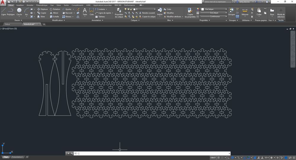
After experimenting with the lasercutter I’ve decided to make a press fit kit using parameter shapes to try to make a tree.
I decided to go with 6 mm thick cardboard with a Kerf setting of 0.2 mm.
I first made a parametric design in Fusion 360.I then wanted to do a test part to check the save DXF for laser cut add-in in Fusion 360 with a 0.2 parameter as the kerf. It worked fine so I prepared all my parts to optimize the positioning in the lasercutter. I’ve noticed that if we have two lines on the top of each other, the laser will cut two times. I used the remove duplicates function in autocad and it worked well, the laser only cut ounce.
 |
 |
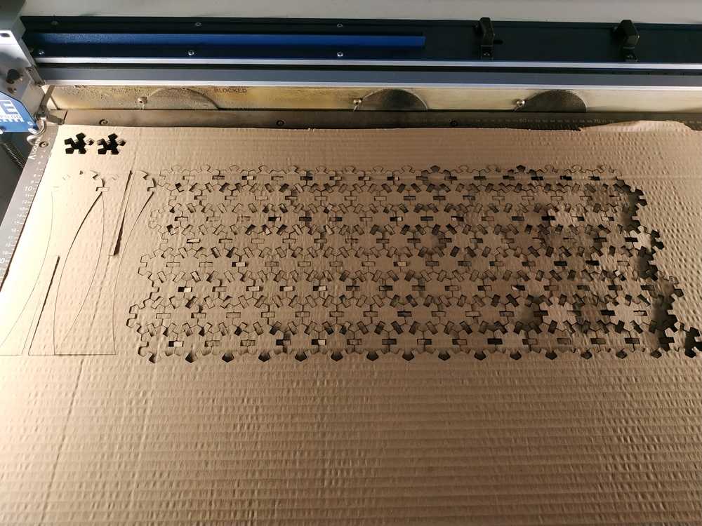
I then cut it in the epilog fusion M2 (75W - CO2). Using the following parameters :
- Speed : 10
- Power : 30
- Frequency : 50
- Passes : 1
- Time : 23 mn 40 s
While I removed my parts some of them went below the lasercutter bed.
 |
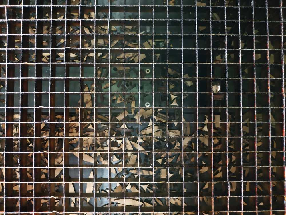 |
I then assembled everything.
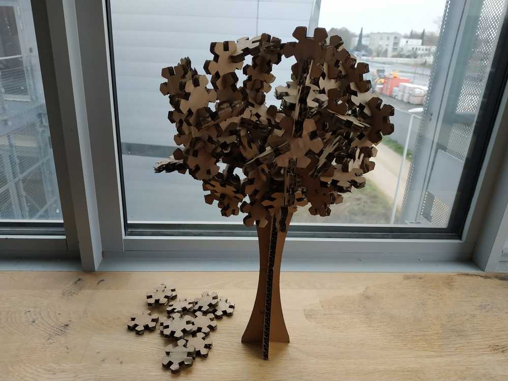
NOTE : It wasn’t a party of pleasure to assemble everything for few reasons :
- I wanted to go for an organic shape so I went random (didn’t work well)
- I reached a critical mass before parts started to fall
- I used the parts many times which leads to a tendancy of damaging them
- I used the “elasticity” of cardboard to connect parts easily creating tension in the system
- I wanted to use all the parts I cut which was a bit too much
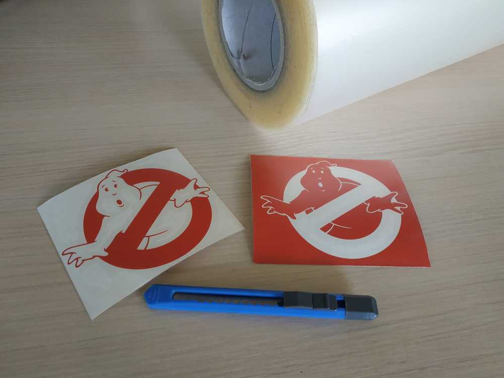
Using the vinylcutter
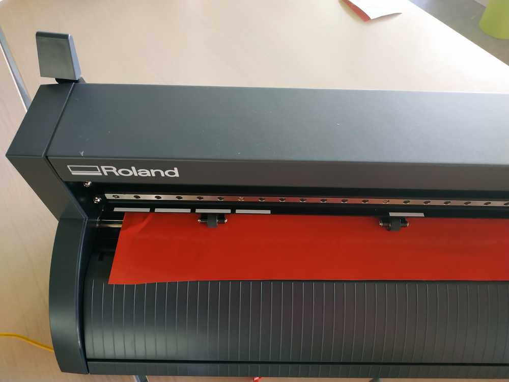
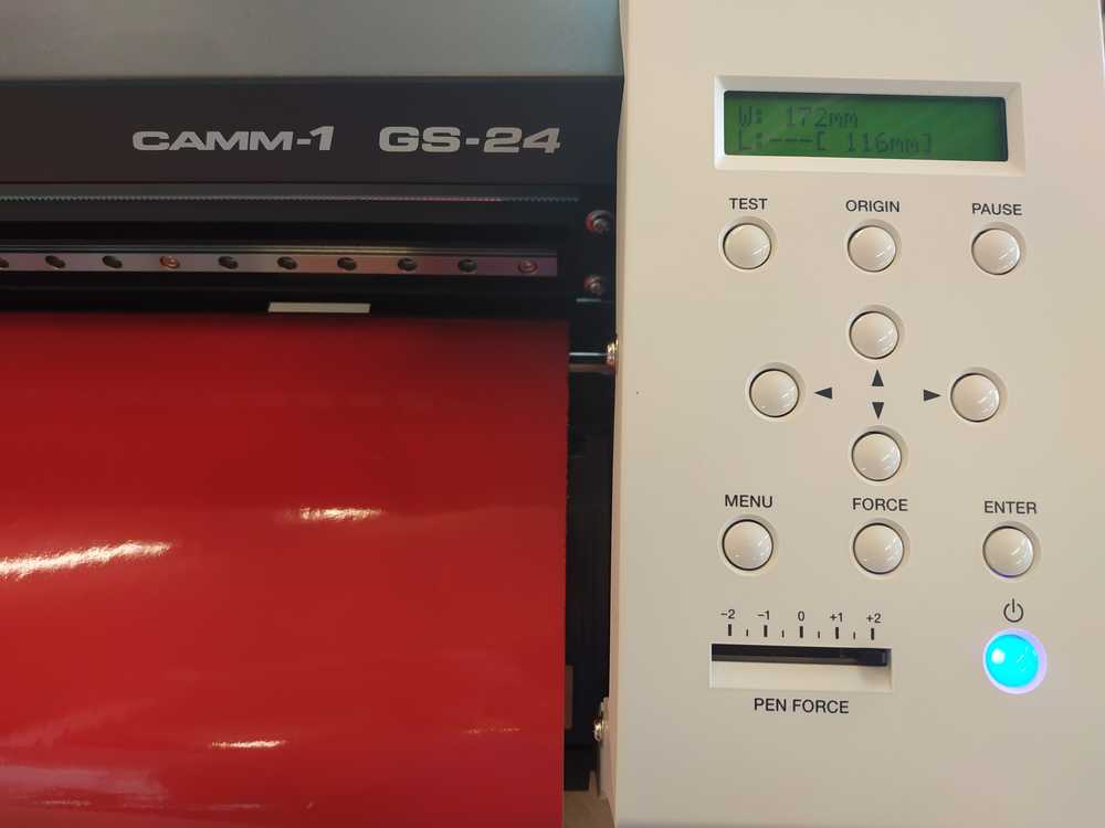
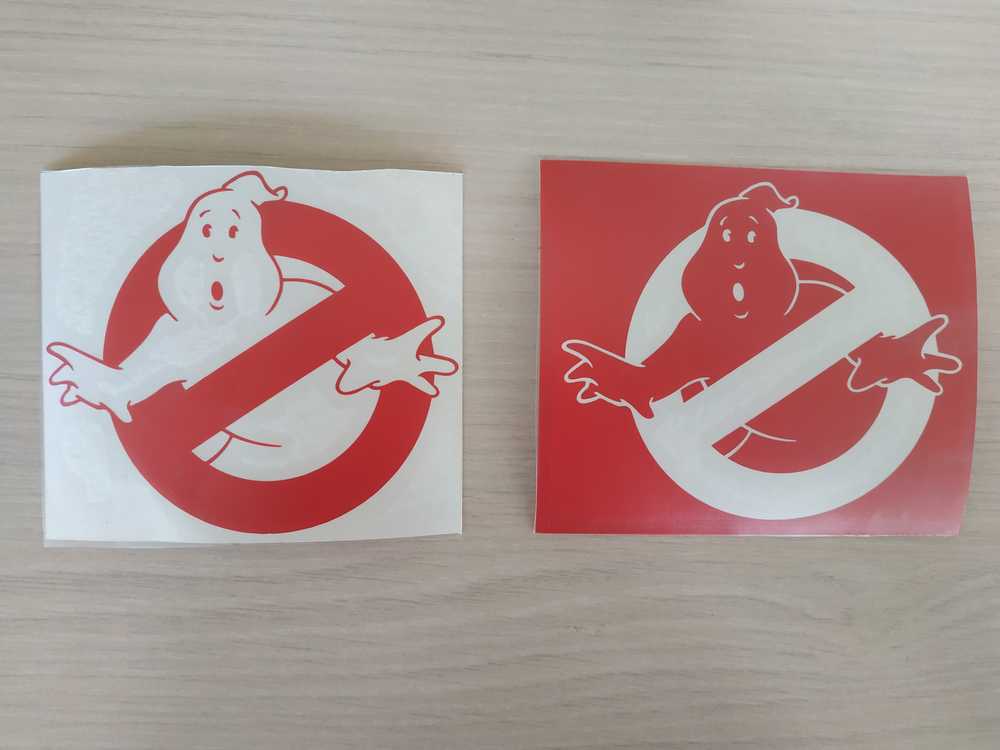
I used the lasercutter to make two ghostbusters signs, one sticker and one stencil to spraypaint it. I’ve used the Roland Camm-1 GS-24.
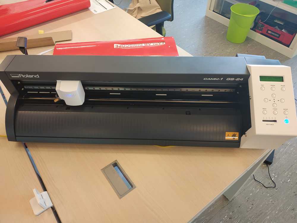
Setup the machine
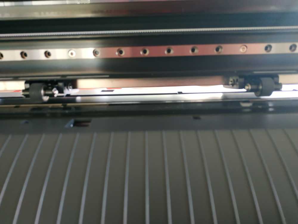
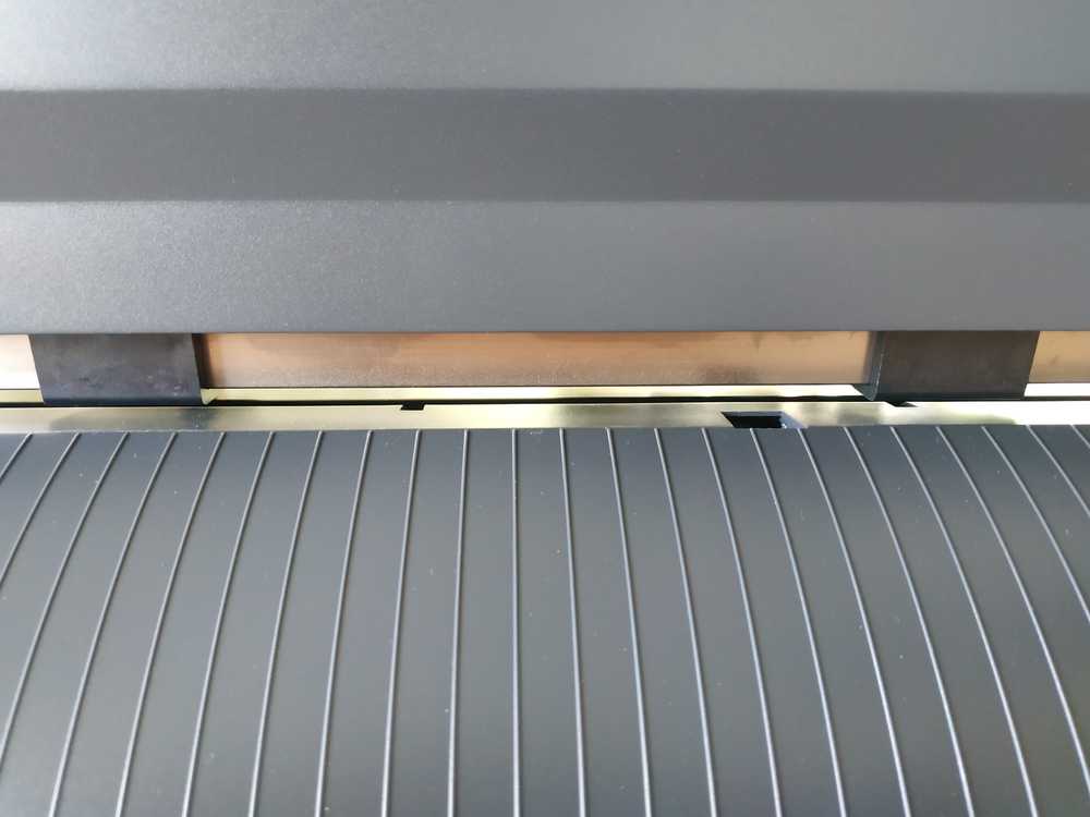
Before using the machine I had to setup it. I manually adjusted the rolls to roughly the width of my cut :
 |
 |
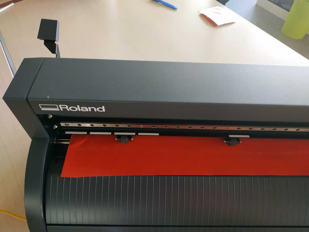
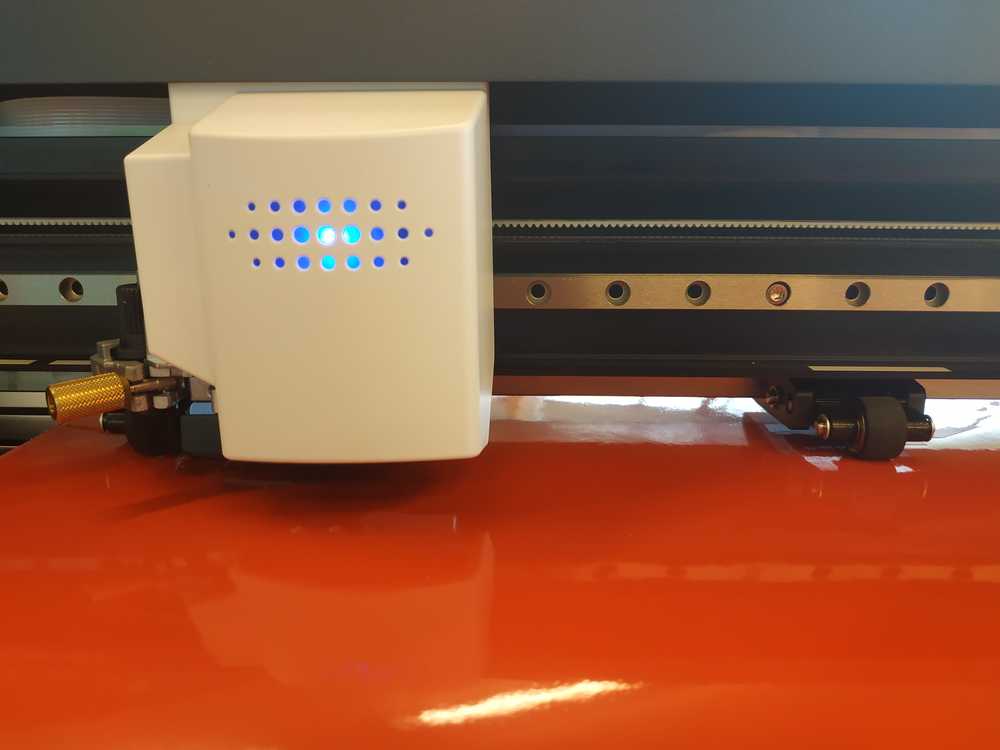
Then I placed a piece of vinyl in the machine and locked it using the lever :
 |
 |
I switched on the machine, it checked its origin and displayed the availabe cutting area (defined by the roller) :
 |
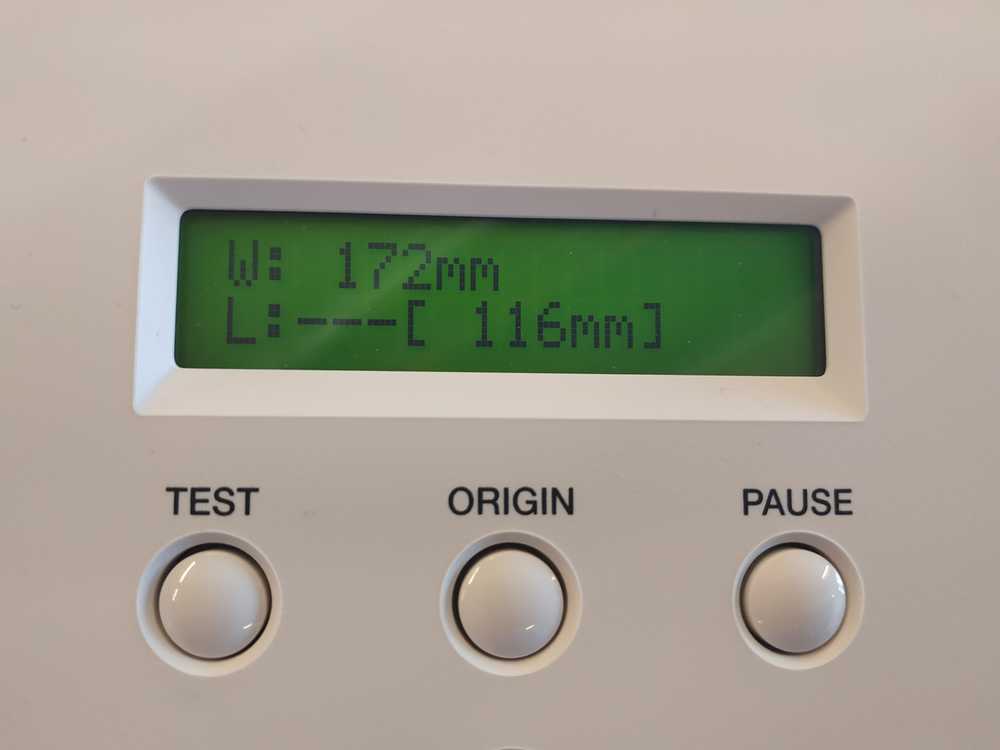 |
You can check if you have enough material for your cut using the controls of the machine. You can also adjust the force of the blade directly on the machine :
Preparing the software
Now I’m ready to prepare my cut file using the machine software CutStudio. First I imported my image into the software :
 |
 |
Then by doing a right click on the image I selected contour outline. This task will only take the contours of your image to make the path for the blade.
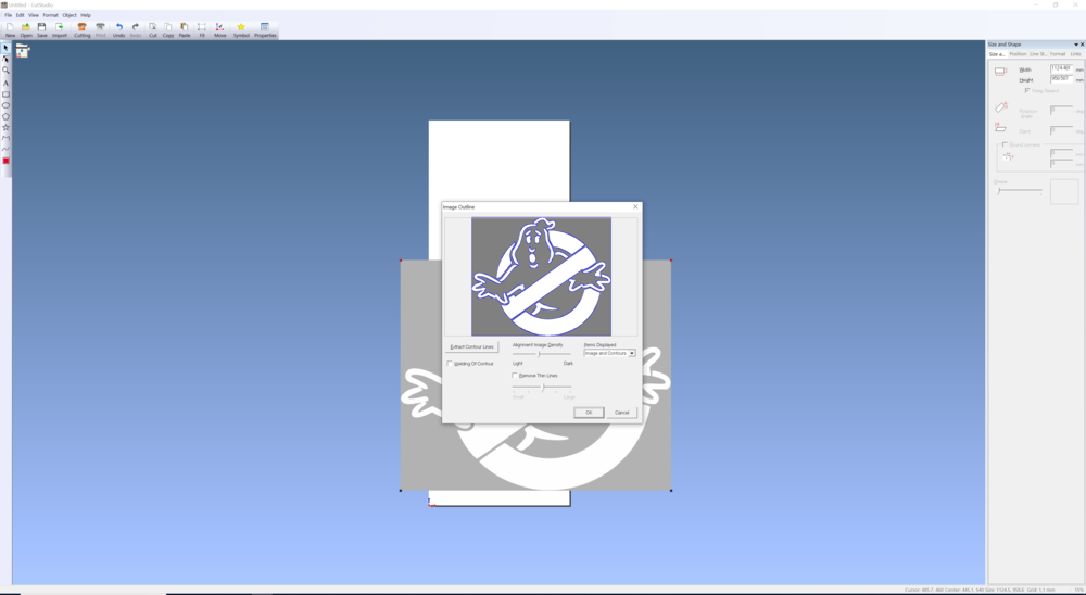 |
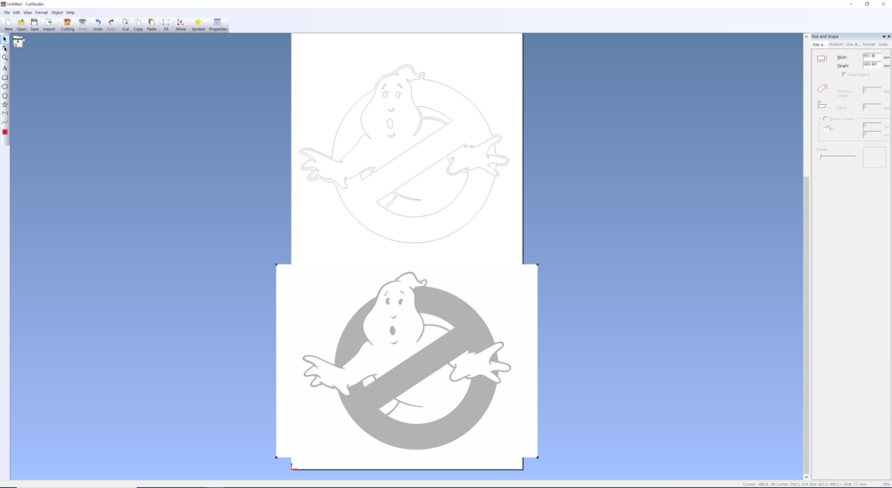 |
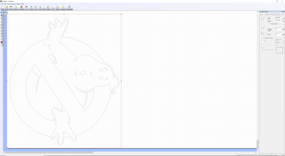
Then I removed the original image and went to the properties of the contours to tune the size of the cut and place it at the origin of the cut area. There’s in the software a few tools to draw manually. I used it to make a rectangle around the logo.
Then I just have to press cut and the machine will start .
 |
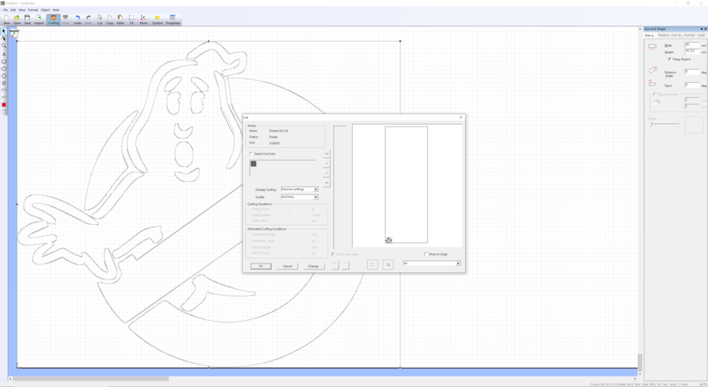 |
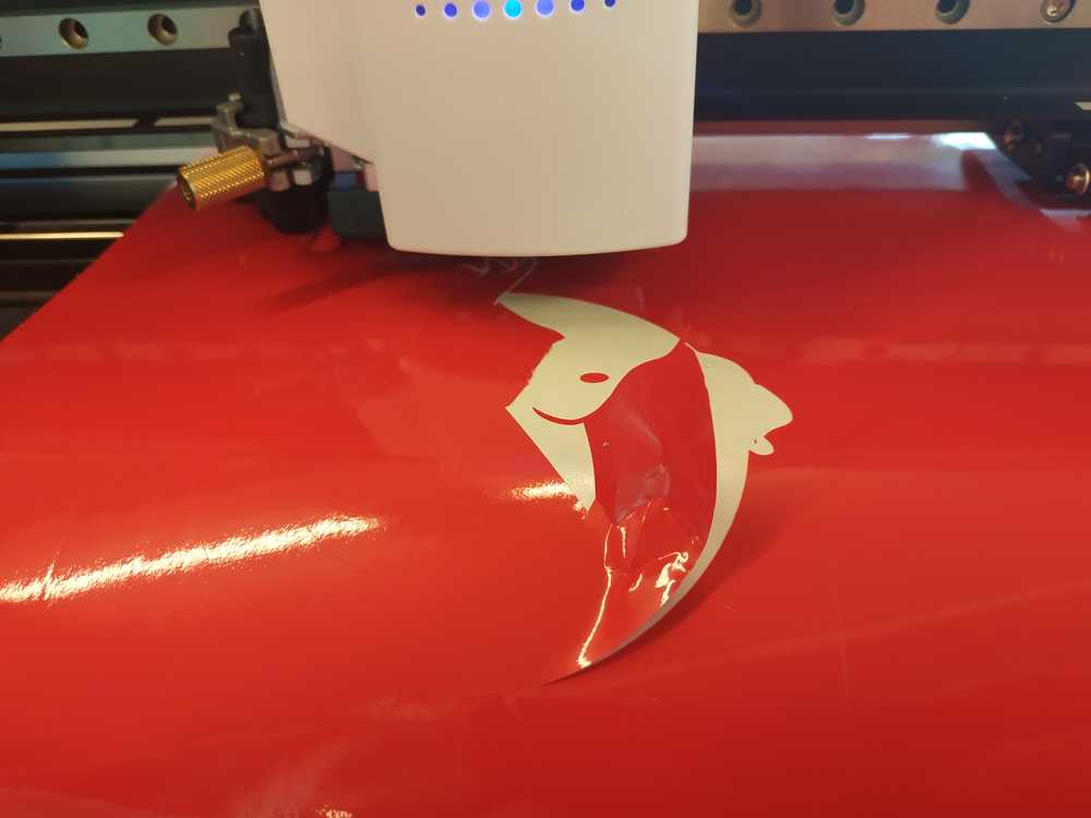
NOTE : My first attemp wasn’t successful because I put too much force into the blade (+2) and the vinyl came off as it was being cut. I made another try reducing the force in the blade (+1) and this time it worked well. I made two cuts.
 |
 |
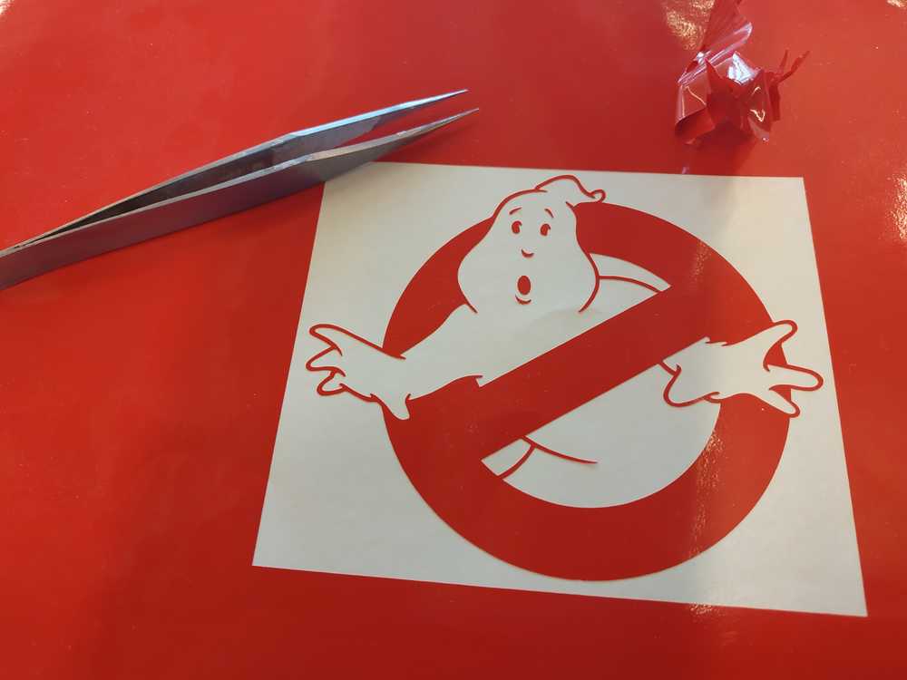
Post processing
Using tweezers I removed the unwanted parts of vinyl and finally I got my two Stickers.
 |
 |
I placed some transferring tape on top of it to easily transfer the two stickers to their final position.
 |
 |
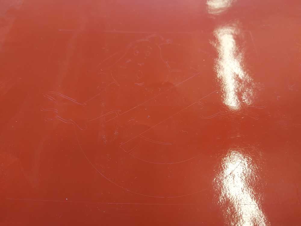
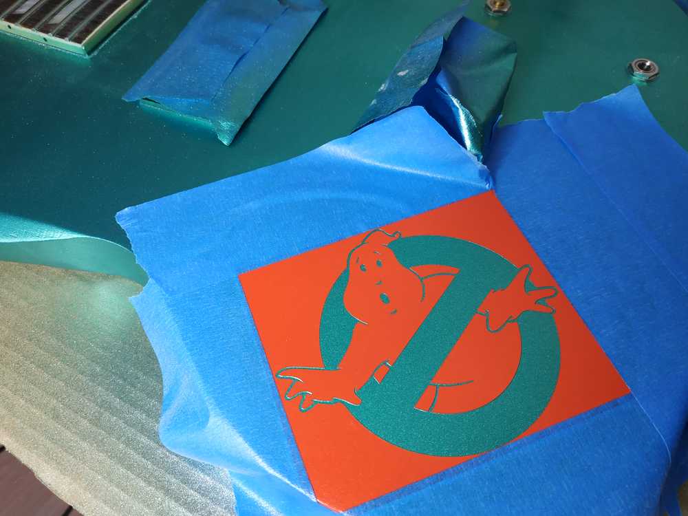
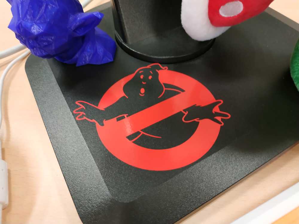
I used the stencil to spray paint a phosphorescent ghost on a guitar and I put the sticker on a monitor.
 |
 |
4.3 Final project work
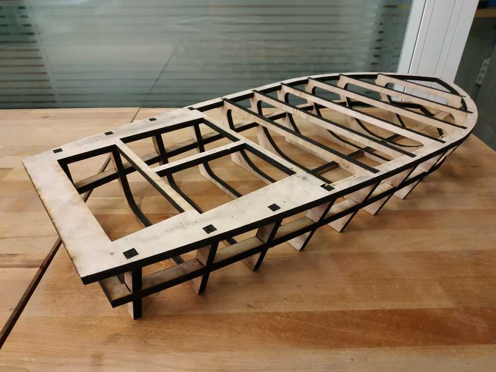
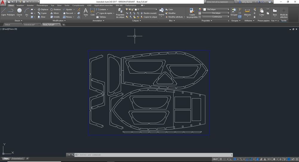
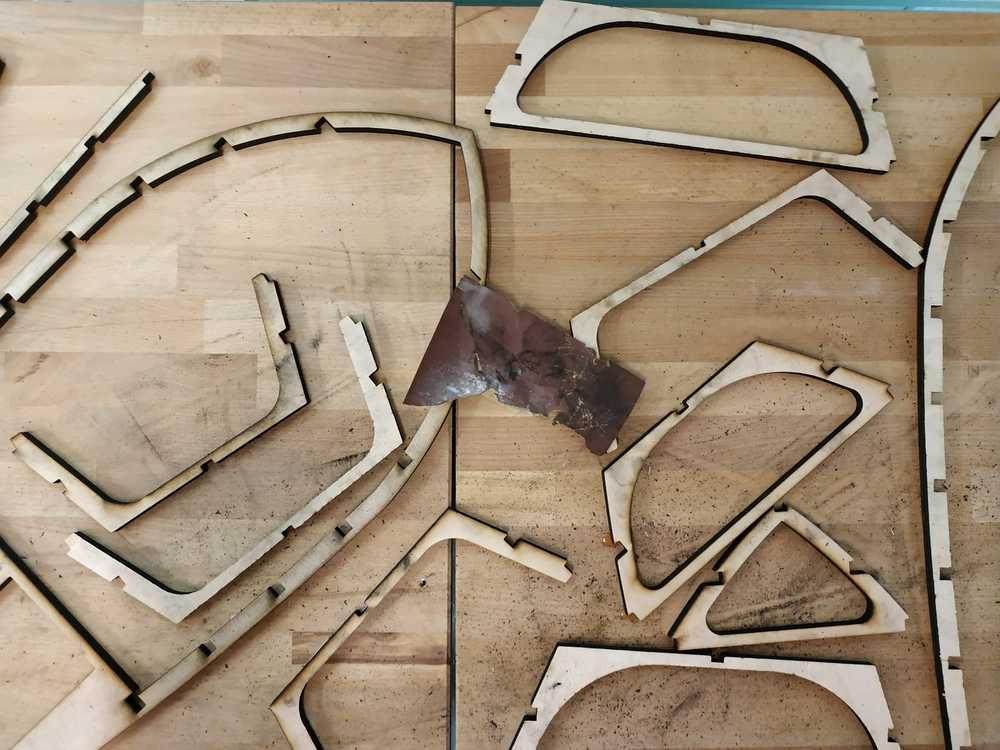
The boat I’m making is divided into four parts. One of these parts is the skeleton which is a press fit structure. This is laser cut in a 10mm beech plank and assemble without glue.
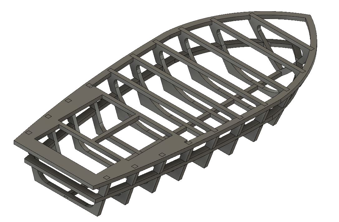
I first used the save DXF for laser cut add-in in Fusion 360 to export all the parts of the skeleton. I then aranged all the parts in autocad and managed to make them all fit in one plank (1000mm x 750mm).
I then cut it in the epilog fusion M2 (75W - CO2). Using the following parameters :
- Speed : 2
- Power : 100
- Frequency : 50
- Passes : 2
- Time : 1 h 20 mn per pass
 |
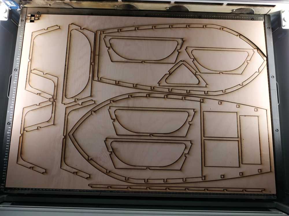 |
After the first pass it seems that some parts where cut but I decided to go for a second one to secure the cut. It was also the parameters I’ve found during my tests so I sticked to it. I missplaced a bit my parts in Coreldraw and add a part cut. It’s not a big issue for my design. I also found out I forgot two lines, that I cut at the end to complete my kit.
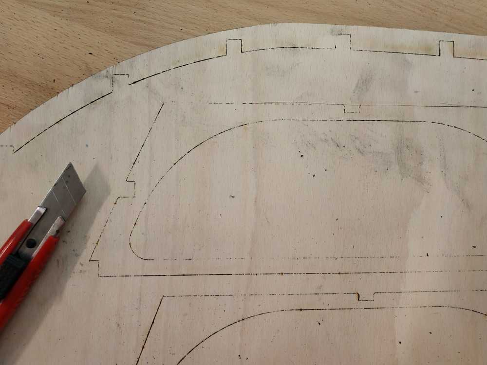
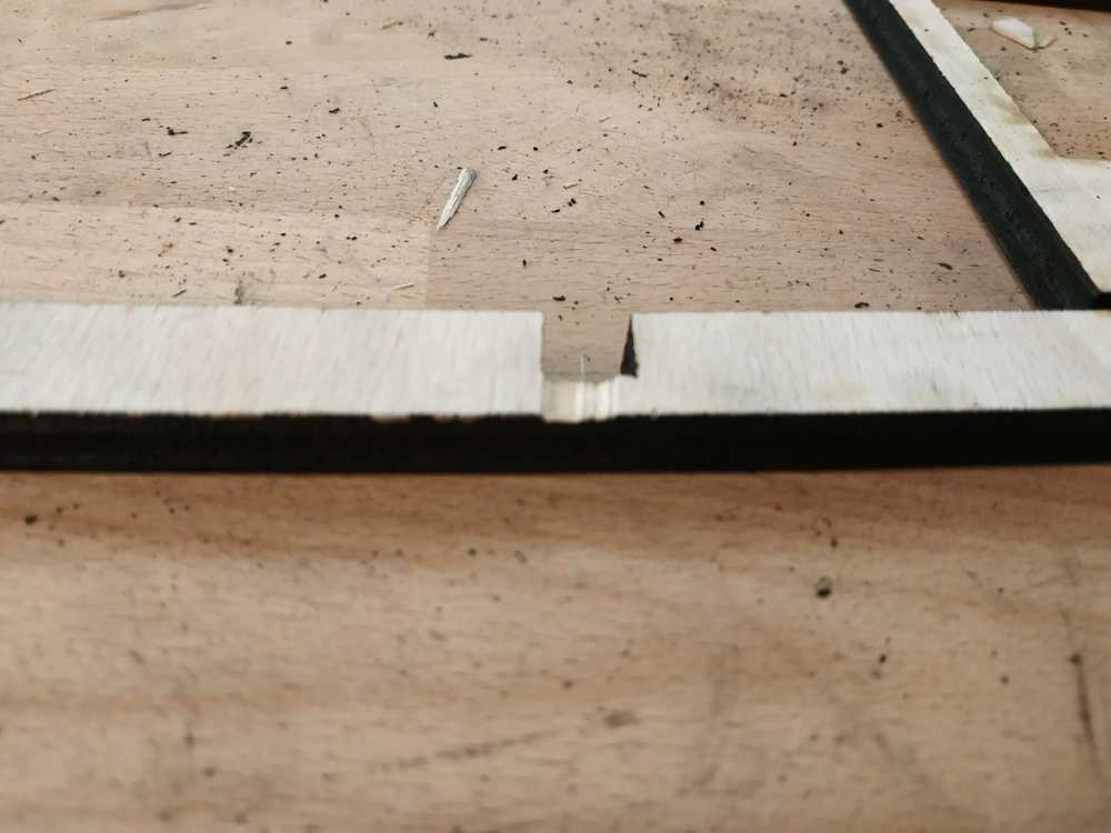
I then tried to remove all the parts from the plank and found out two issues :
- Some parts were burnt (I didn’t have accurate dimensions)
- Some parts weren’t fully cut (I had to use a cutter blade to finish the cuts)
Trying to remove all the parts, I damaged some parts a bit. This should not be a big problem for my design.
 |
 |
Everything became dirty with the burnt part so I decided to use sand paper to clean a bit all the parts.
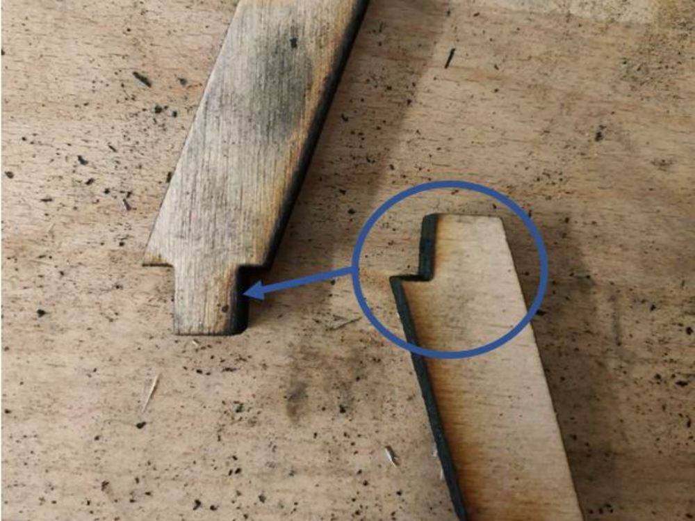
I then assembled evertyhing. I did a mistake in my design and had to cut three parts again to make everything fit properly.
 |
 |
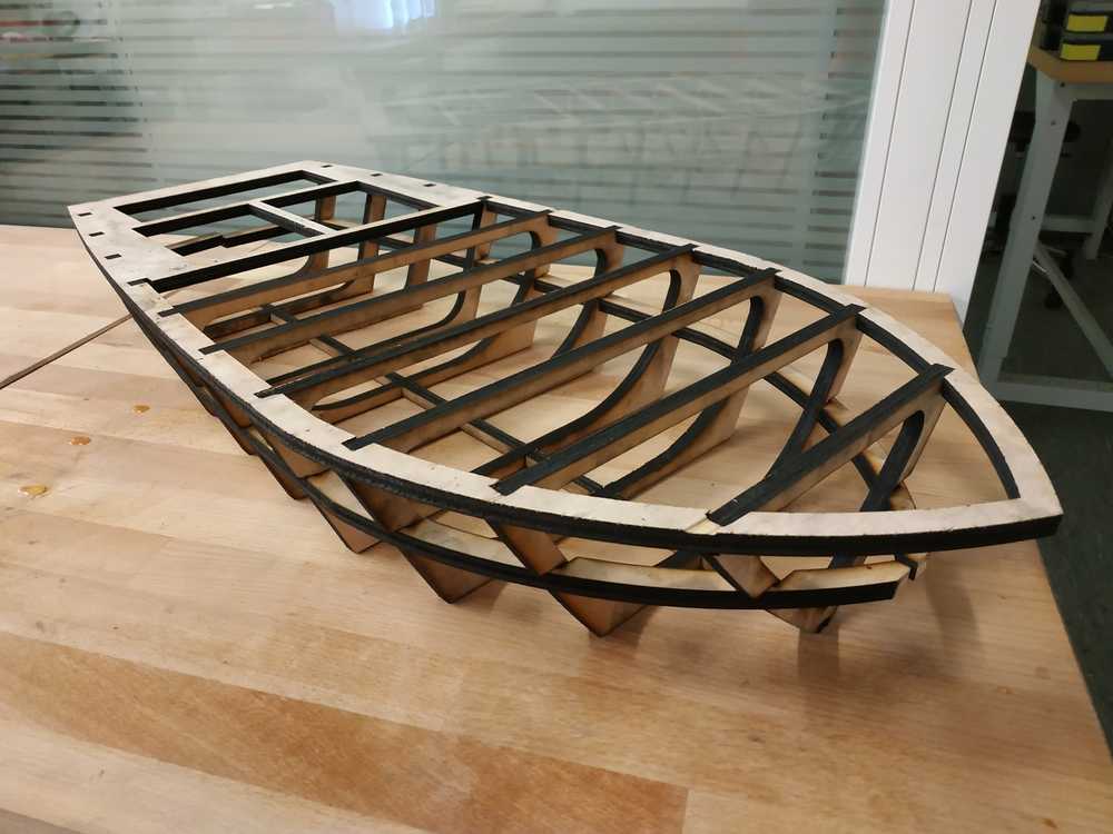
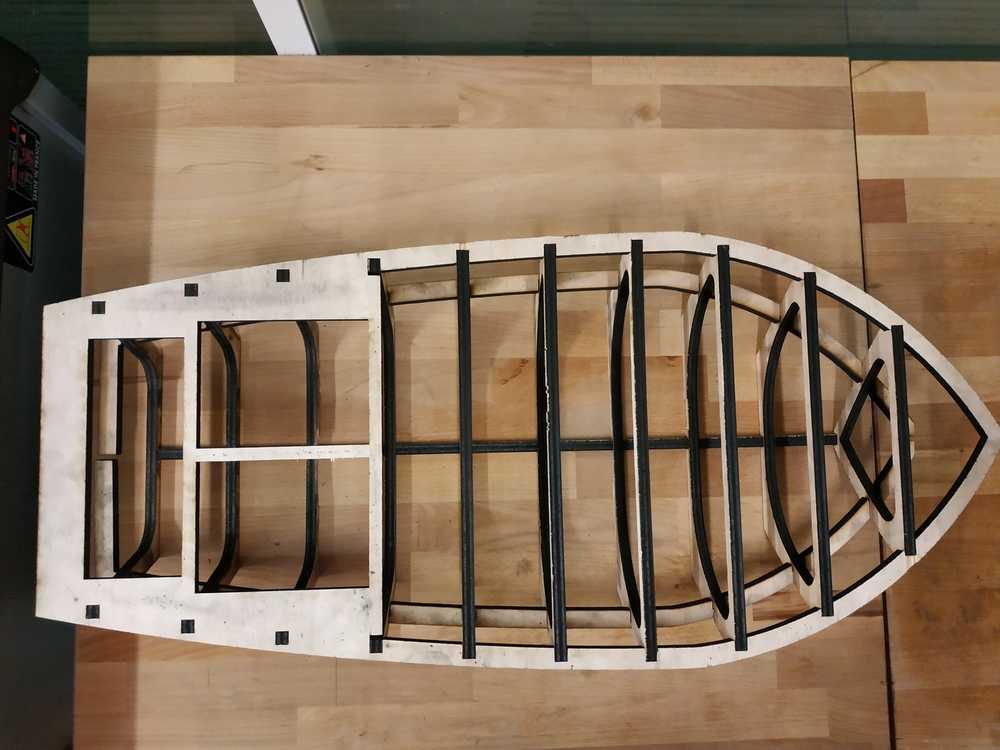
Finally everything fits and looks like the way I expected it to.
 |
 |
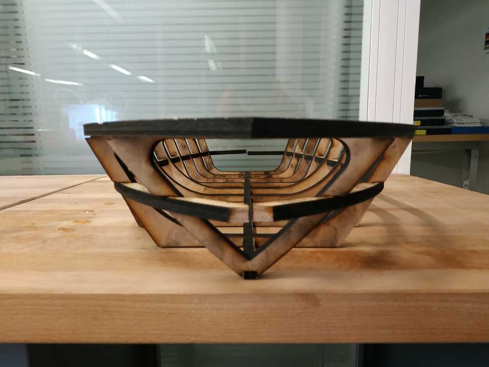 |
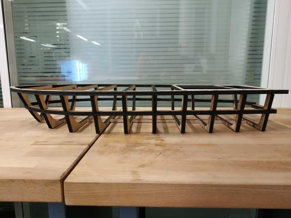 |
However here are some things I can improve to this design :
- Make a fit link for the middle horizontal part
- Redue the damaged parts
- Try to do the skeleton in other materials (maybe with cardboard, i can make it more rigid using epoxy)

Ce(tte) œuvre est mise à disposition selon les termes de la Licence Creative Commons Attribution - Pas d’Utilisation Commerciale - Partage dans les Mêmes Conditions 4.0 International.