7. Electronics design
Group assignment
Use the test equipment in your lab to observe the operation of a microcontroller circuit board
Individual assignment
Redraw the echo hello-world board, add (at least) a button and LED (with current-limiting resistor) check the design rules, make it, and test it, extra credit: simulate its operation, extra credit: render it
| Documentation |
|---|
| 1. HelloBoardTraces.png |
| 2. Main.C |
| 3. EagleFiles |
This week I’m going to learn about the equipments we have in the lab to monitor what’s going on in a PCB. I’m also going to design a hello board and upload a code in it to see if it’s working.
7.1 Group assignment
The purpose of the group assignement is to check the equipements available in the lab to see what’s going on in a circuit board. For this we have two main equipements :
- a multimeter
- an oscilloscope
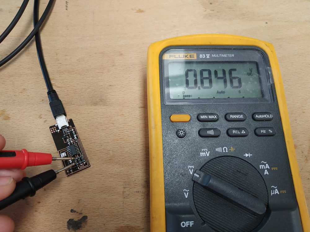
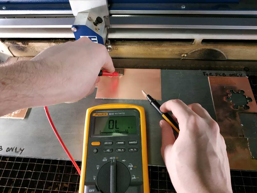
The multimeter
We use this equipement mostly for few reasons :
- Check an electrical potential (voltage)
- Check the value of resistance
- Check the electrical continuity in our paths
 |
 |
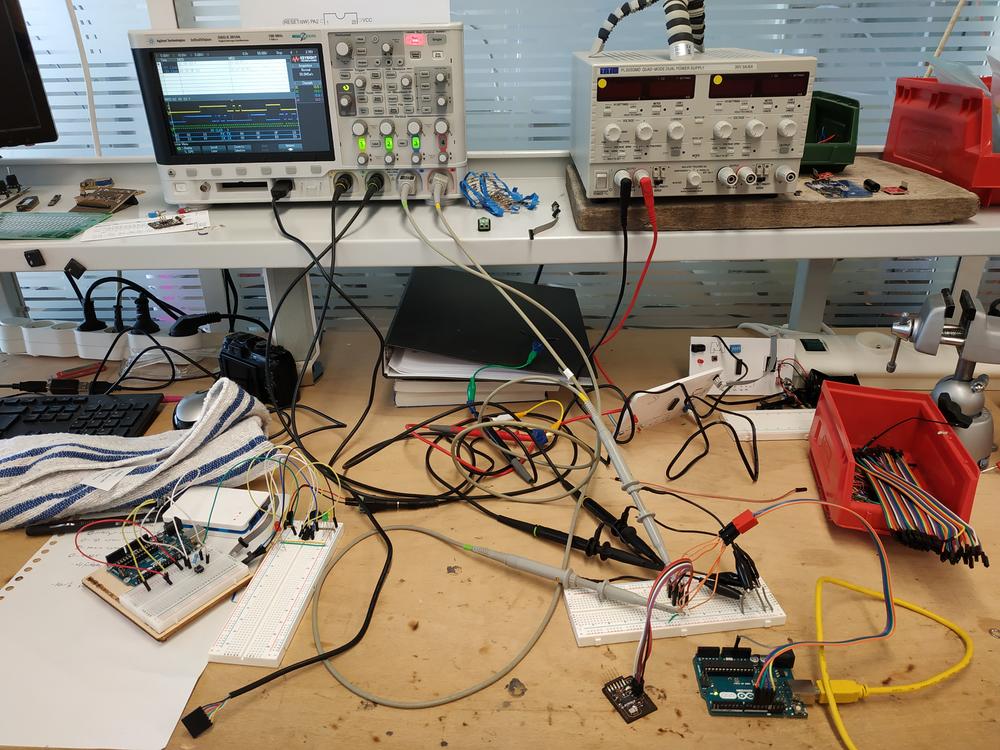
The oscilloscope
This device allows us to visualise the signal in our cirduit board. We use probes to see what’s going on between two electrical potentials.
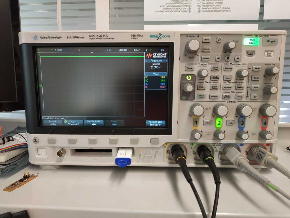 |
 |
Using this oscilloscope, we can make screenshots of the screen and get a clear image of what’s going on. There are four inputs so we can see four signals at the same time in our circuit.
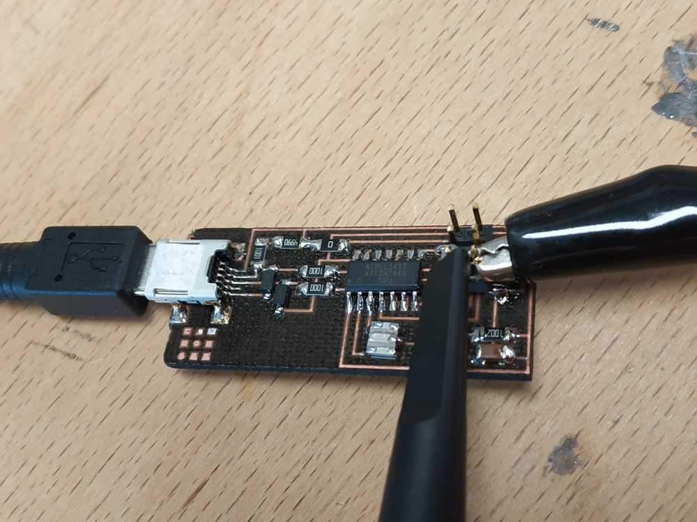
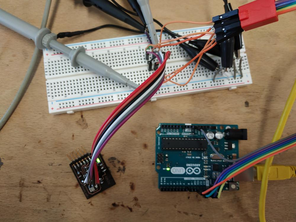
During the Input device week, I’ve made a PCB that I used to visualize on the oscilloscope the ISP connection between my computer and my board while uploading a code.
First I used a breadboard to simplify the connections between the ISP connector, my ISP and the ocilloscope. Then I probed Four pins of my ISP (RESET, MISO, MOSI, SCL).
 |
 |
In our oscilloscope we have a function to analyse the ISP / I²C communication and visualize the hexadecimal code transfered to the board.
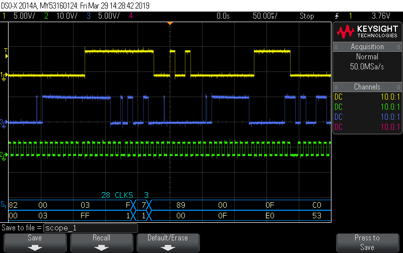
NOTE : Here we can see the MISO (yellow), MOSI (blue) and CLOCK (green). We can clearly see that the clock is here to set time and that MISO is an echo of MOSI.
7.2 Individual assignement
Trying tinkercad.com
Tinkercad.com is a website where you can simulate basic circuits with microcontrollers.
For this week assignment, I tried to make a simple hello world board using an ATtiny45. The very impressive thing with this website is that you can have a visual representation of your system, you can code the Attiny45 (using scratch or C-code) and simulate it.
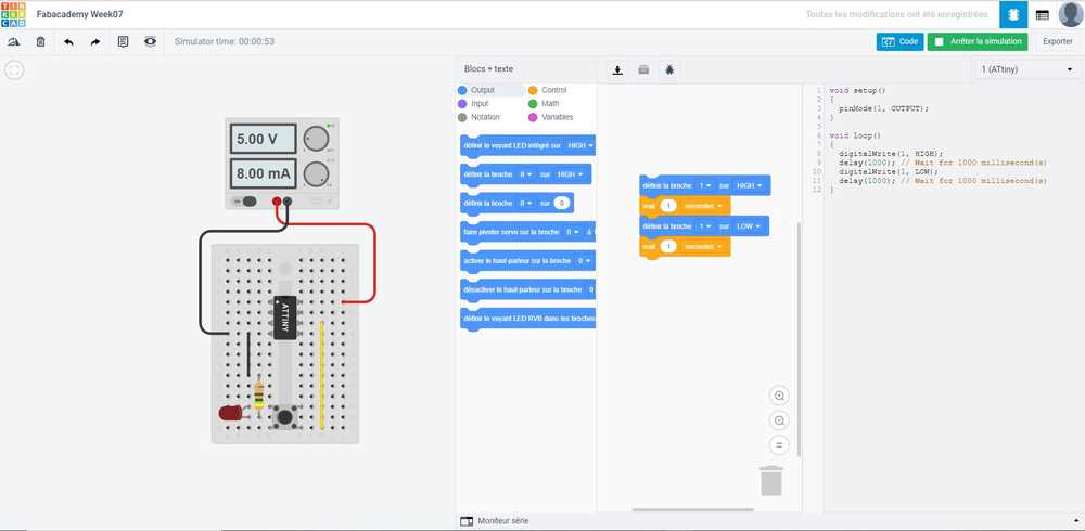
Everything went on well, here is a video of the working design.
This tool is very powerful to learn about coding and microcontrollers but it’s limited in terms of number of components.
Making the PCB using Eagle
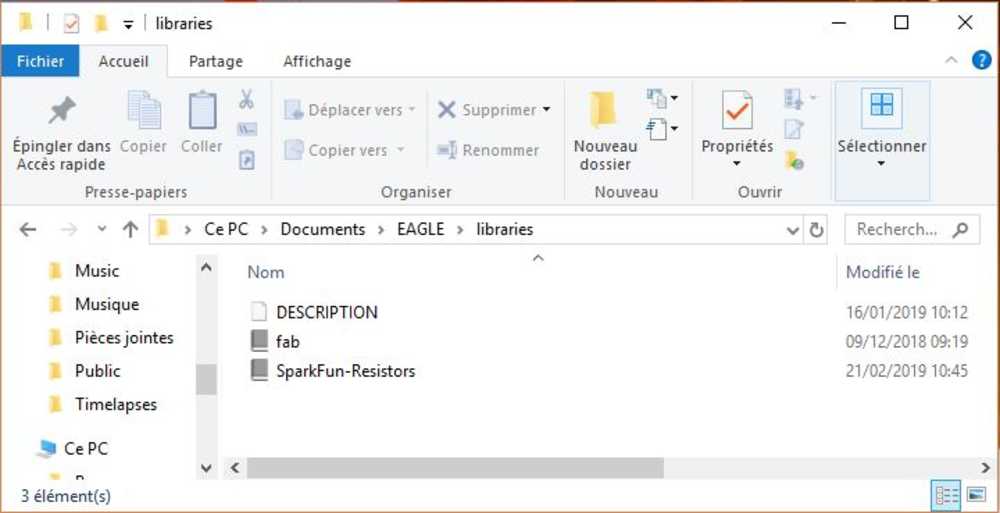
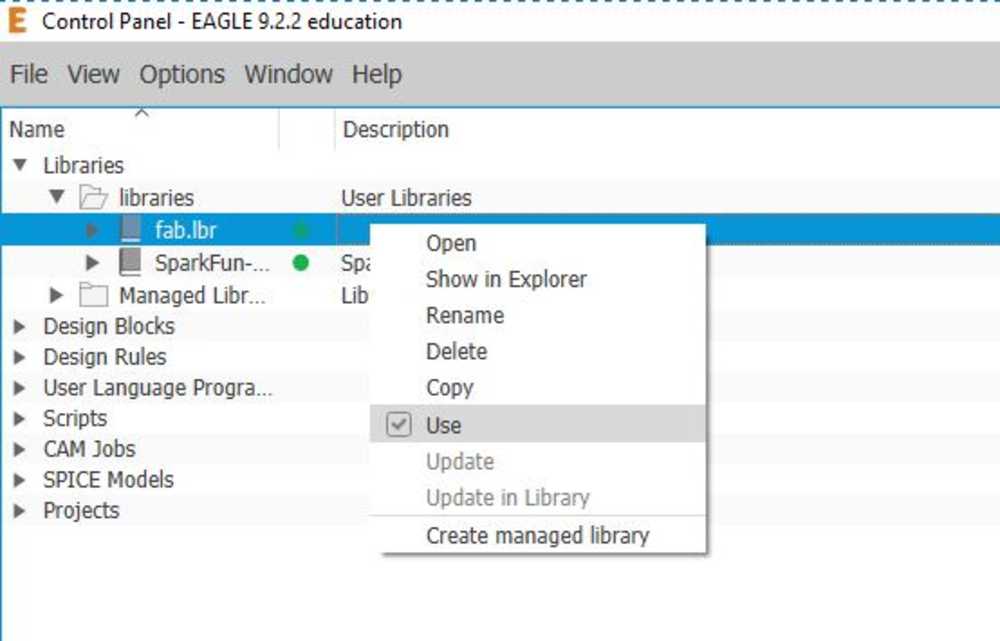
Installing the Fab Library
I used Eagle for the first time for this project. Once I installed it, I also download the fab library I placed it in C:\Users\ducro\Documents\EAGLE\libraries. In eagle after making a new project, I made sure to enable the library.
 |
 |
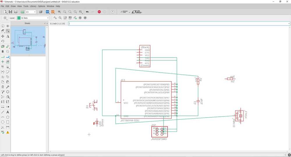
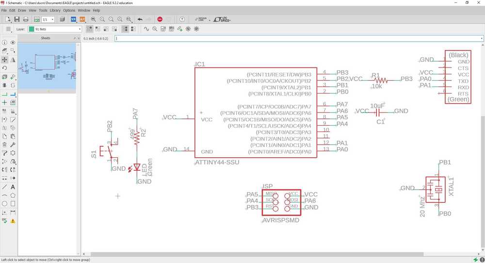
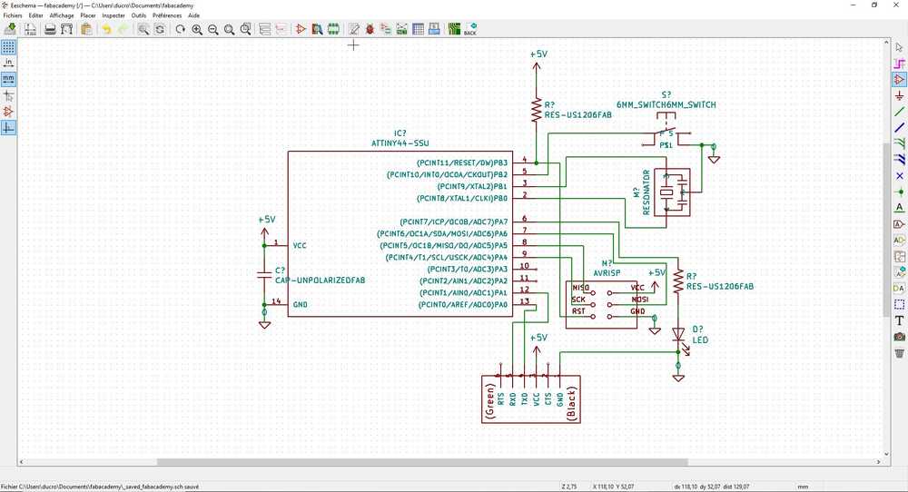
Making the schematic
Then I started a new schematic where I placed the different components. To connect the components together I first made some paths using lines. It quickly started to be a huge mess, so I arranged the parts and used label to connect the components together.
 |
 |
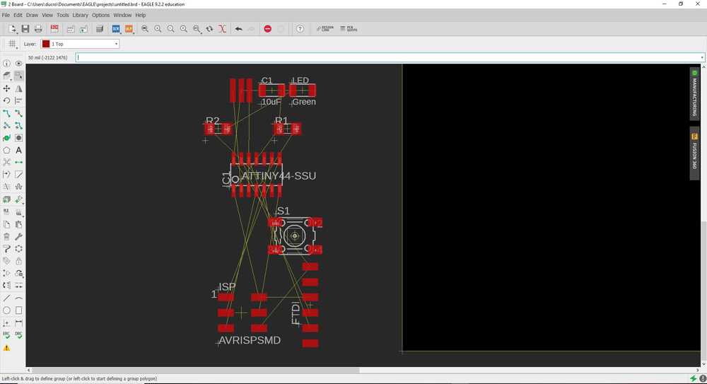
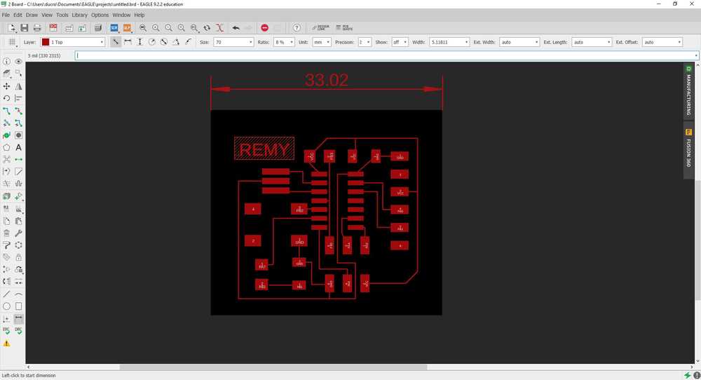
Making the board
Once evertyhing was connected, I switched to the board view. I re-arranged eveything to make all the paths. I also arranged the contour to make the PCB the size I wanted.
 |
 |
NOTE : I let some room for the laser to cut the PCB contour without damaging the paths.
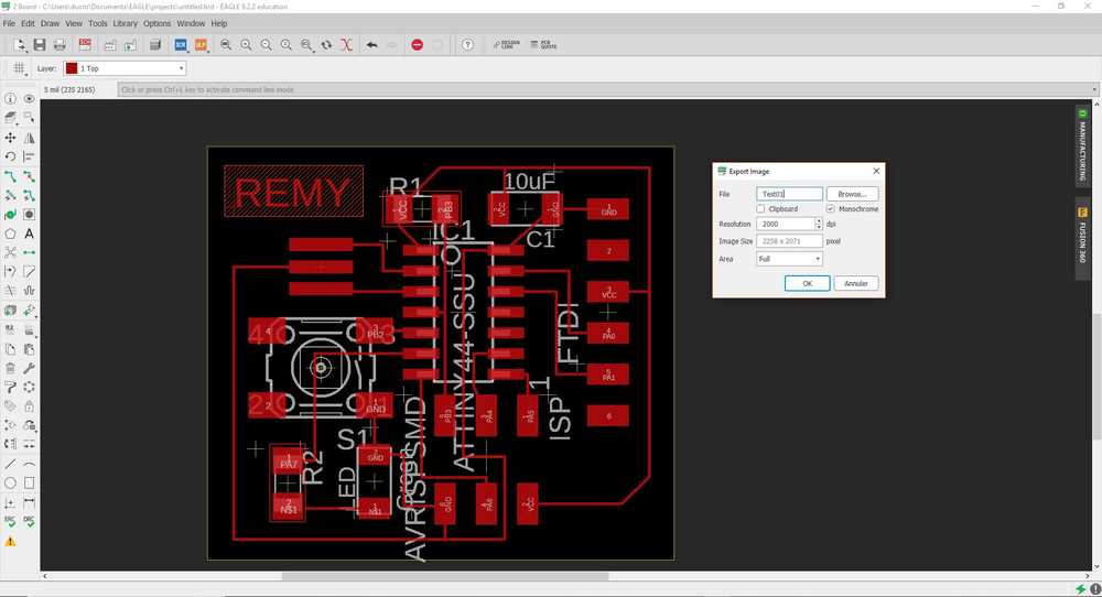
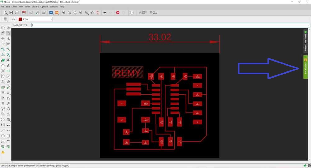
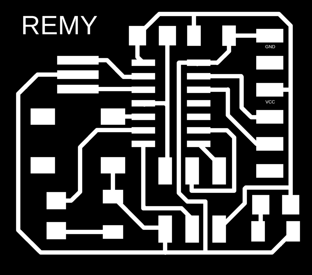
Exporting the paths file
I then selected the layers I wanted to export and exported the layer as a PNG image.
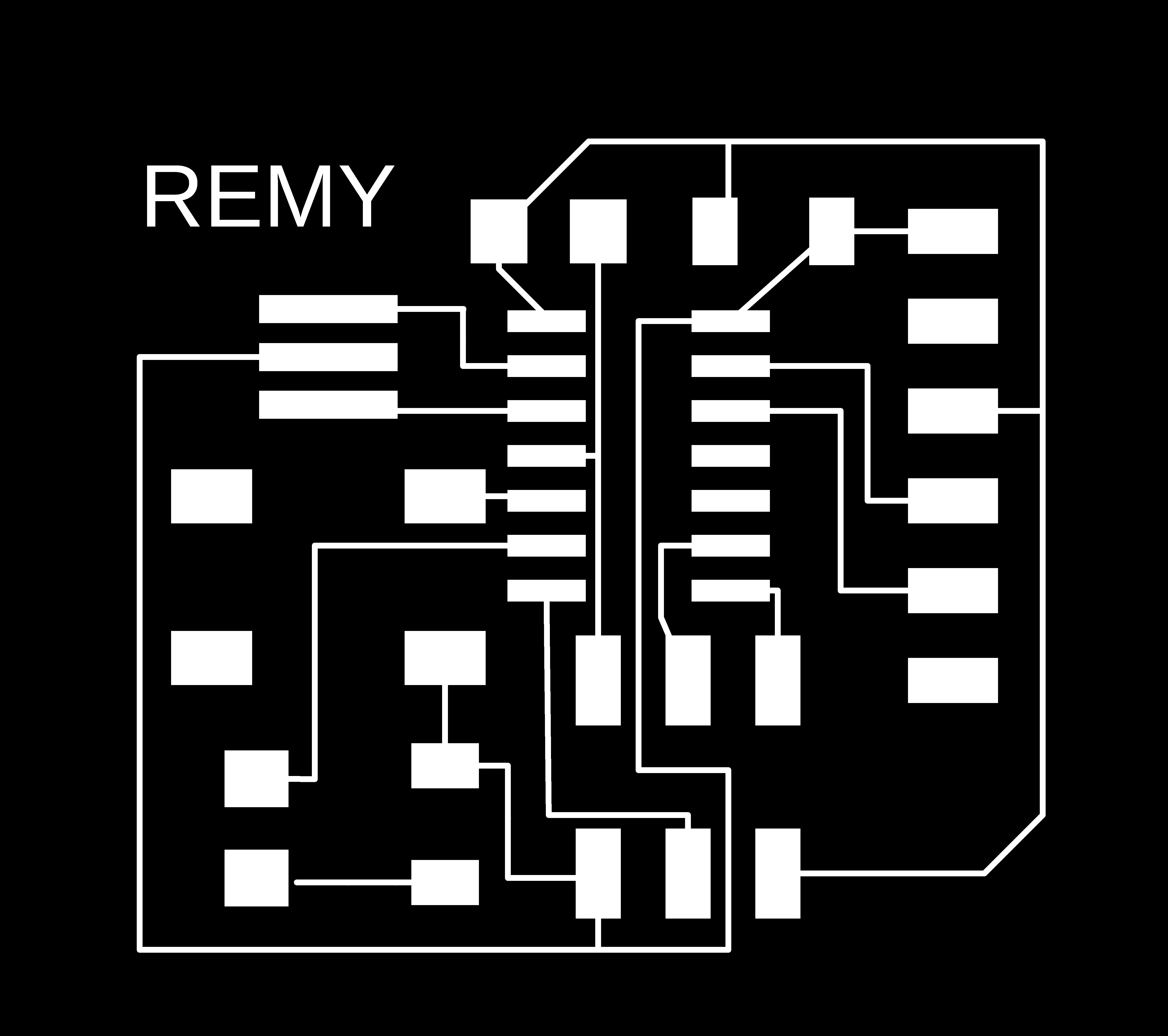
NOTE : the good setting to export the image is 1000dpi .PNG
Rendering the PCB from eagle to fusion360
In the board section in eagle, there is a Fusion360 button on the right. Once you press it, you have to select a folder in your Autodesk cloud to put your PCB and the software will automatically create a PCB in 3D. Here is the result.
 |
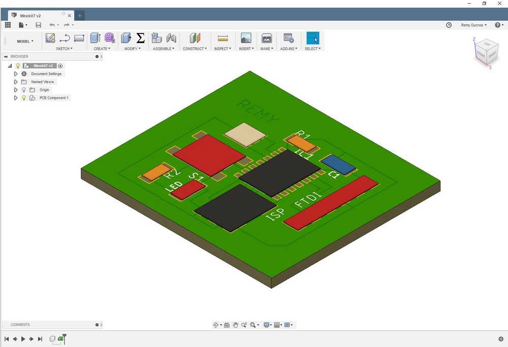 |
This representation can be improved if in the library we put a 3D CAD model of each component. Yet it’s still pretty impressive I think.
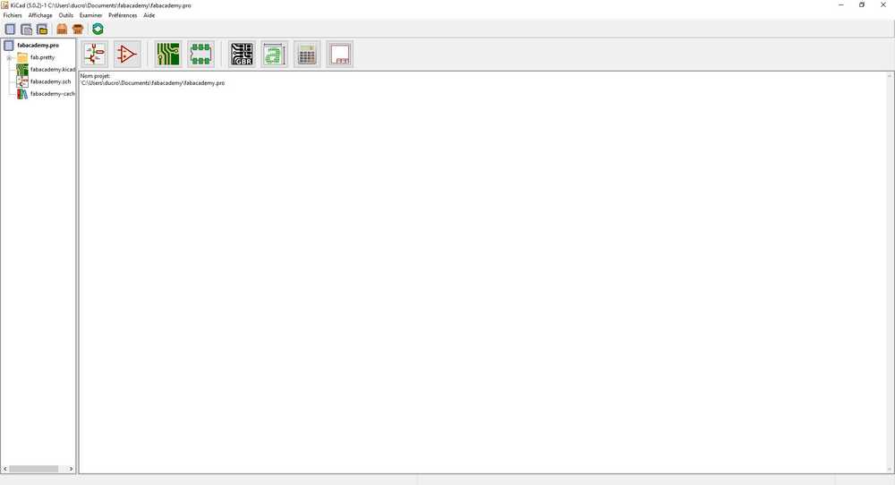
Trying Kicad
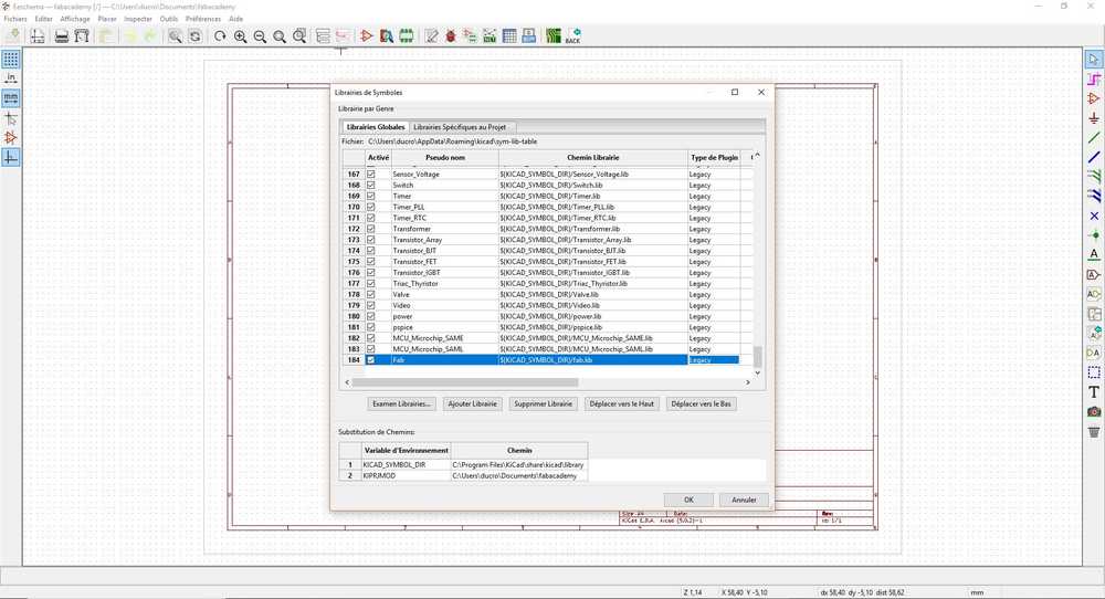
Installing the Fab Library
I wanted to try Kicad as well. Once I installed it, I also add to install the fab Library. After creating a new sketch, I went to Preferences then Library manager and I created a new library named fab and I set the path for the software to get the library.
 |
 |
Making the schematic
In the schematic view, I uploaded the needed components from the Fablibrary. This time I tried to connect all the components using pahts. I used labels only for the power supply and the ground. When everything was done I had to assign the footprints for each component.
 |
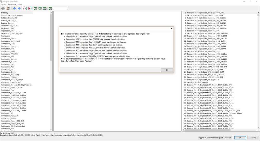 |
I have an issue, I couldn’t find the footprints of the components I used. I’ve made a mistake importing the library somewhere and I’m still trying to figure out what the problem is.
Making the PCB
I made my PCB using the lasercutter and from the PNG image I’ve got from EAGLE. I uploaded the image in CorelDraw and started the raster but the size was not accurate. I went back to Eagle and found a dimension tool and I measured the lenght of my PCB.
 |
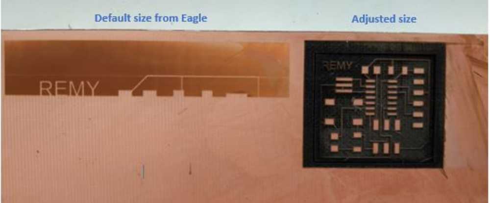 |
I ajusted the dimensions in CorelDraw and started the raster, and everything went on smooth. I cleaned the PCB using silicon and alcohol. I used the following parameters to make the board :
- Type of laser : FIBER
- Power : 100
- Speed : 16
- Frequency : 1
- Passes : 11
I made the soldering and my PCB was complete.
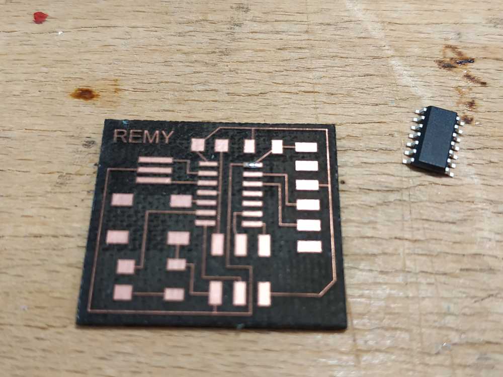 |
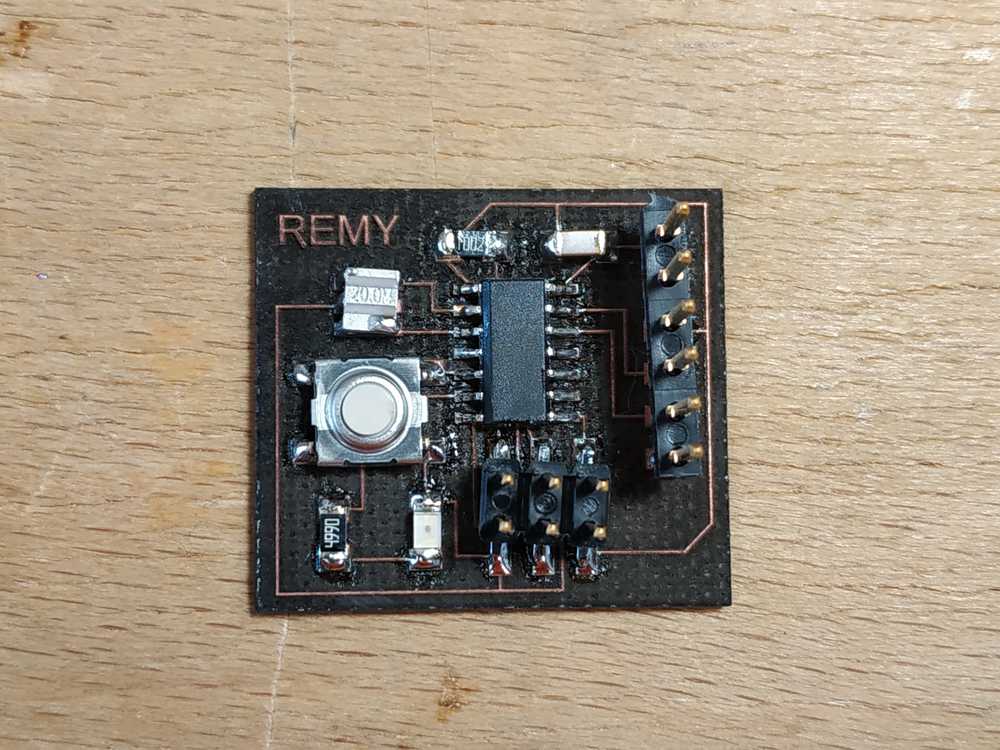 |
Programming the microcontroller
Using the provided code
I first dowloaded the files hello.ftdi.44.echo.c and hello.ftdi.44.echo.c.make in a folder. I opened my montior and changed directory to the folder. I tried to upload the provided code using my FabISP. However when I run the make -f hello.ftdi.44.echo.c.make I had an error : Error 1
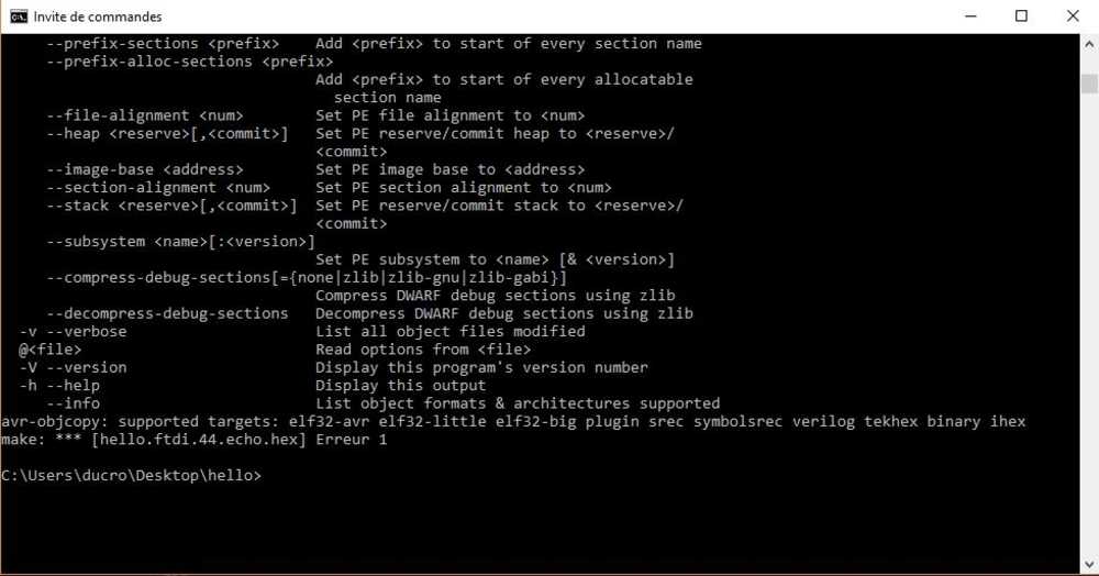
I’m still not quite sure that my FabISP is working properly. To go further, I tried to upload my own code.
Trying to program everything on my own
- I made a C-code to make the LED blink every second
main.c
/*
  * Blink Attiny84.c
  * Created: 19/01/23 4:44:29 PM
  */
#include <avr/io.h>
#include <util/delay.h>
int main(void)
{
   DDRB = 0b11111111;
   DDRA = 0b11111111;
     while (1)
     {
                PORTB = 0b11111111;
                PORTA = 0b11111111;
                _delay_ms(1000);

                PORTB = 0b00000000;
                PORTA = 0b00000000;
                _delay_ms(1000);
     }
        return (0);
}
- I connected the board with my FabISP and I gave a 5V DC supply to the board.
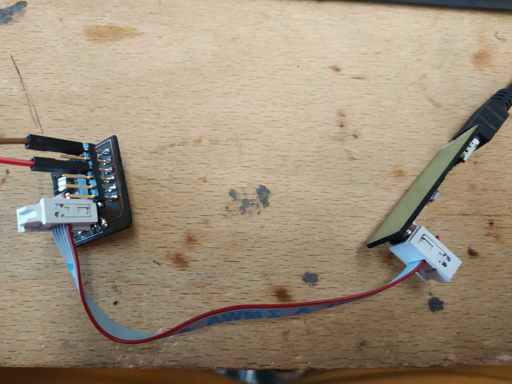
-
I placed the code in a folder where my files are and ran the command
avr-gcc -g -Os -mmcu=attiny44 -o main.elf main.o. It created the main.o file -
I ran the command
avr-objcopy -j .text -j .data -O ihex main.elf main.hex, it created the hex file -
I ran the command
avrdude -p t44 -c avrisp2 -U flash:w:main.hexto flash the program, but I had a problem. My fabISP was here in my device manager but I wasn’t able to identify the COM it was plugged in.
After some investigation I’ve identified two potentiel problems :
- The width of the path may be too tight
- The line going below the microcontroller may be too close from the pads
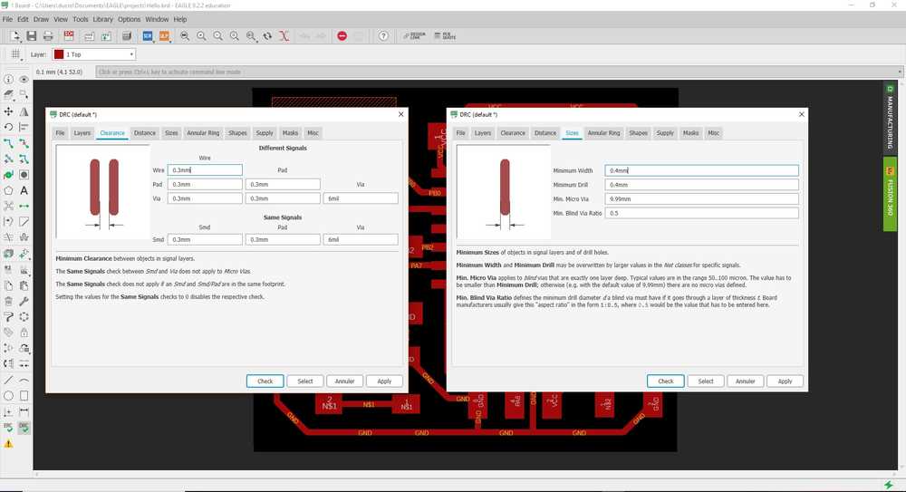
Adjusting my design
Considerng the possible mistakes, I added some design rules in the file :
- Width of the path = 0.4 mm
- Clearance = 0.3 mm
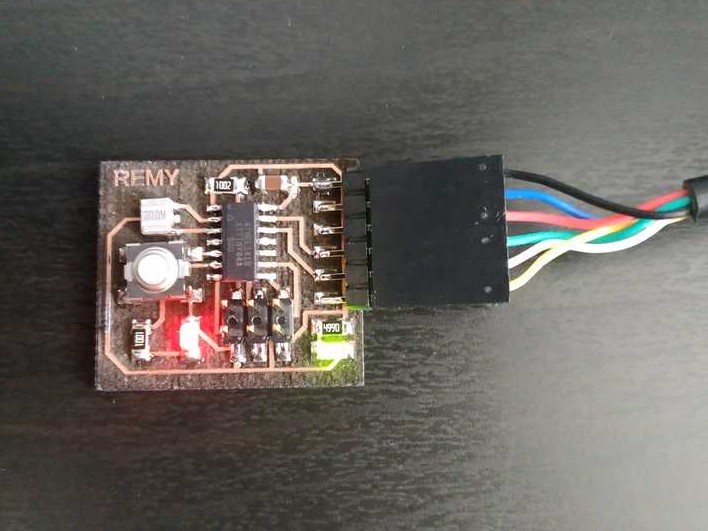
Then I made the routing job another time. I also decided to improve the user experience for this PCB and I put an LED (with a current limiting resistor) on the 5V pin so we know if the board get its power supply. I also tried to add some signs to know where is the VCC and GND pin in the FTDI connection.
 |
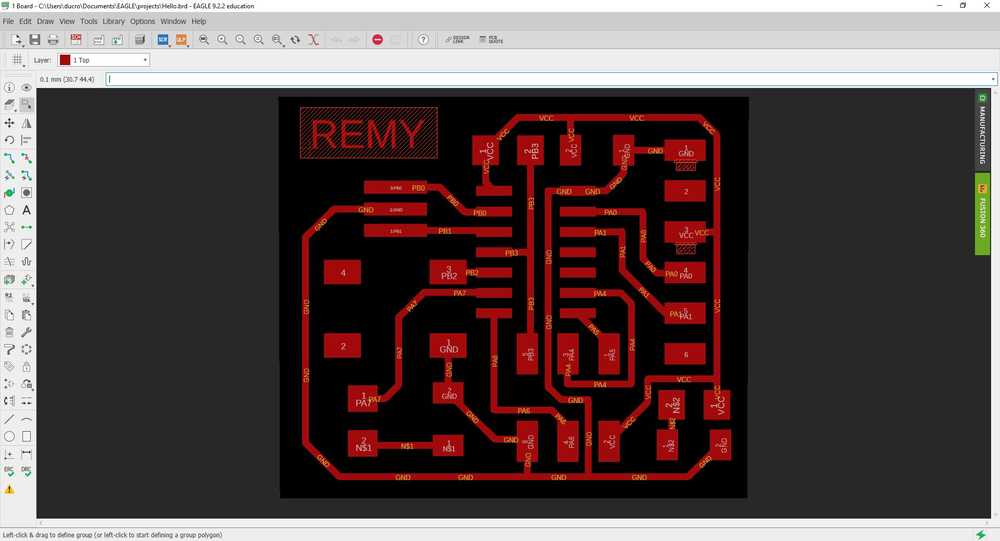 |
Then I made the PCB and solder the components.
 |
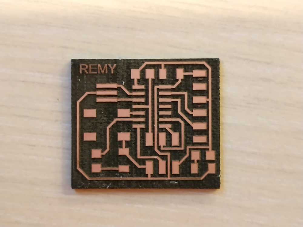 |
NOTE : The VCC and GND signs were too small so it didn’t work.
Finally I uploaded a code in it and it worked well this time.

Ce(tte) œuvre est mise à disposition selon les termes de la Licence Creative Commons Attribution - Pas d’Utilisation Commerciale - Partage dans les Mêmes Conditions 4.0 International.