17. Machine design
Group assignment
- Actuate and automate your machine
- Document the group project and your individual contribution
| Documentation |
|---|
| 1. 3DPrintFiles.stl |
| 2. PCBEagleFiles |
This week, I’m going to actuate and automate my machine to make it work. To understand this work you have to check what I ‘ve done during the mechanical design week.
The spooling system
Actuation
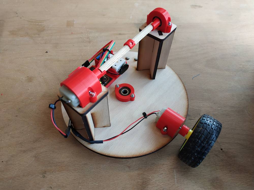
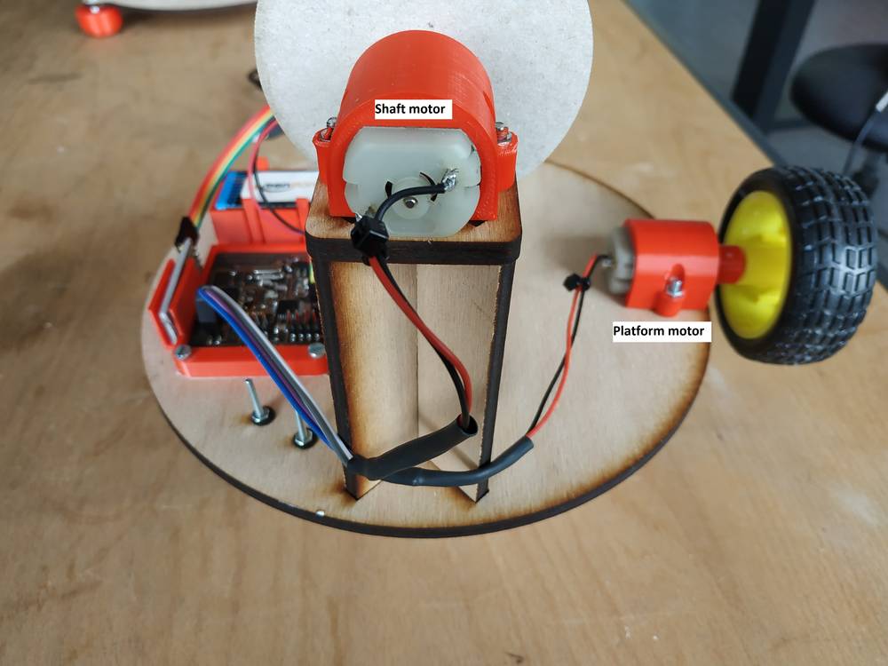
For this level I’ve decided to connect :
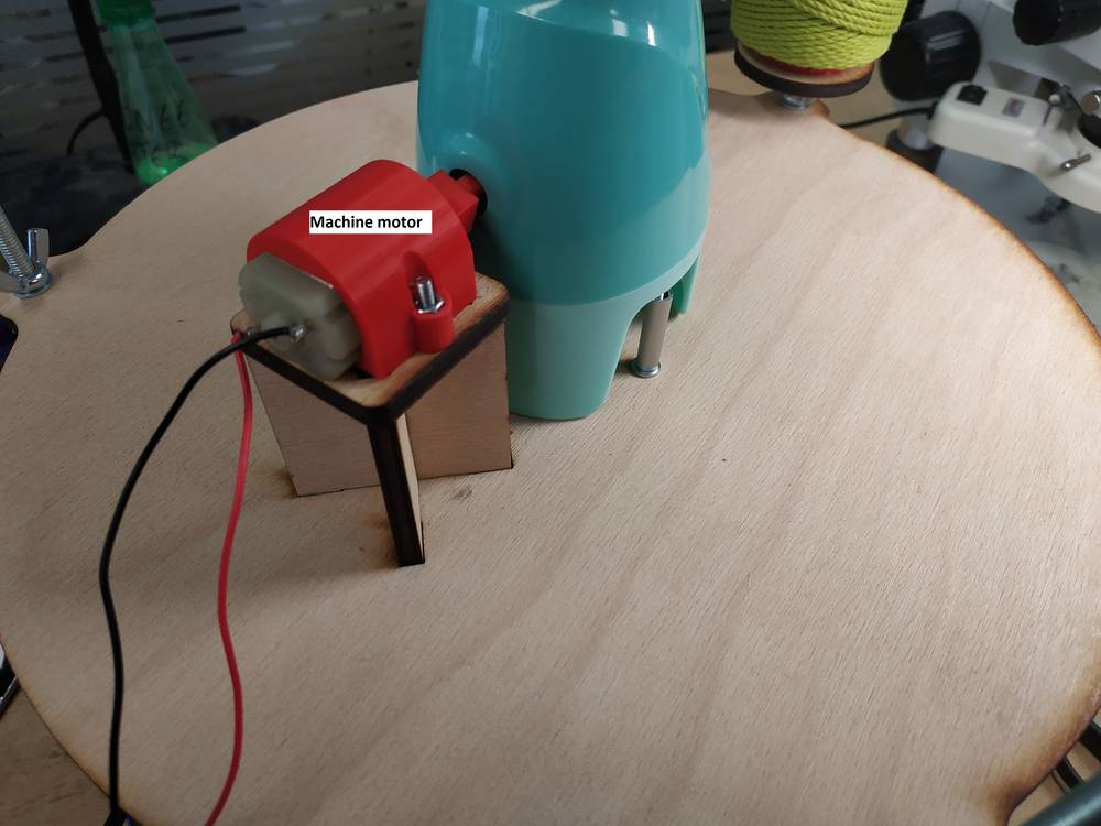
- one DC motor to the wheel to rotate the platform as I needed to rotate the platform fast enough
- one DC motor to the shaft to have a good range of speed
Automation
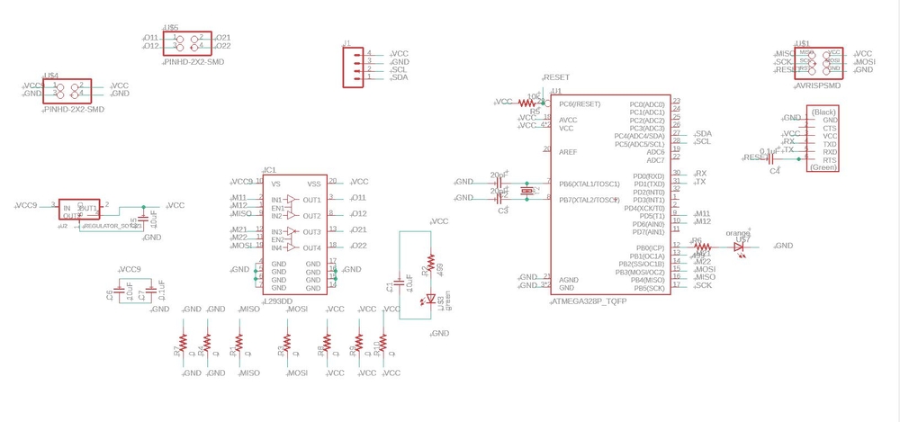
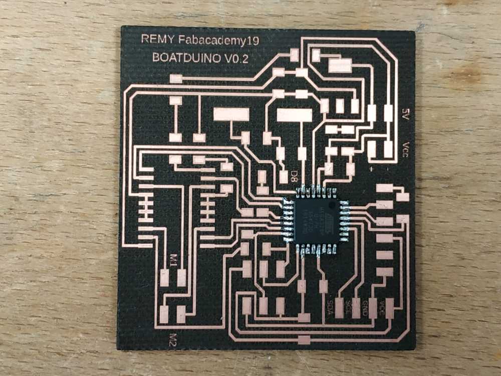
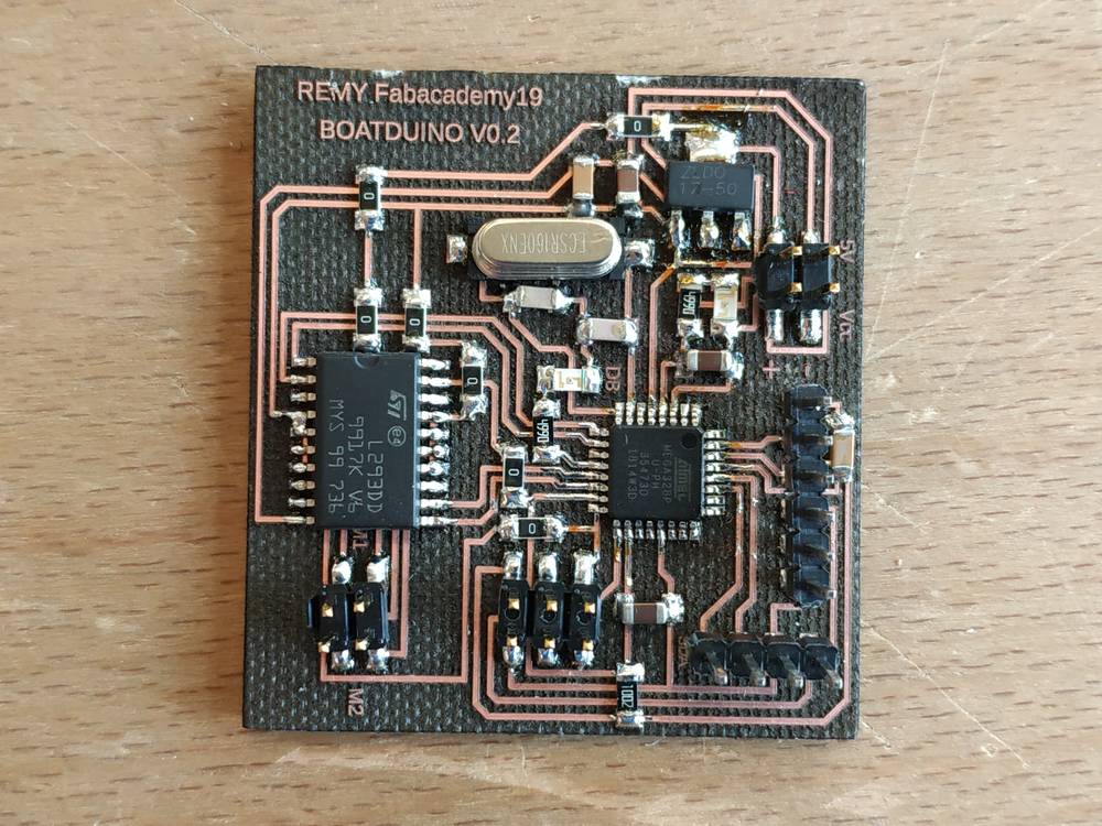
PCB Design
During the output device week I’ve made a PCB to control two DC motors using a H bridge and an Atmel328p. This PCB fits for this project so I used this design.
I took my previous design made on eagle :
 |
 |
Bill of material :
| Atmega328p | x1 |
| 2x3 connector | x1 |
| 2x2 connector | x2 |
| 6 pin header | x1 |
| 4 pin header | x1 |
| LDO5V - ZLDO17-50 | x1 |
| Green led | x1 |
| Orange led | x1 |
| Capacitor 10uF | x3 |
| Capacitor 0.1uF | x2 |
| Capacitor 22pF | x2 |
| L293DD H-bridge | x1 |
| Resistor 0 ohm | x7 |
| Resistor 449 ohms | x2 |
| Resistor 10 Kohms | x1 |
| Resonator 16MHz | x1 |
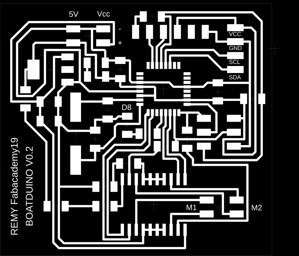
PCB Fabrication
I made the board using the lasercutter. I’ve used the following parameters :
- Laser source : Fiber
- Tupe : Raster
- Speed : 16
- Power : 100
- Frequency : 1
- Passes : 7
 |
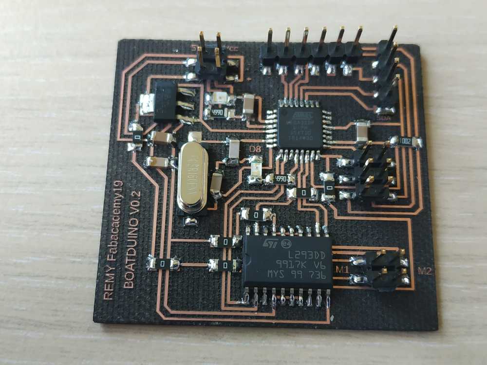 |
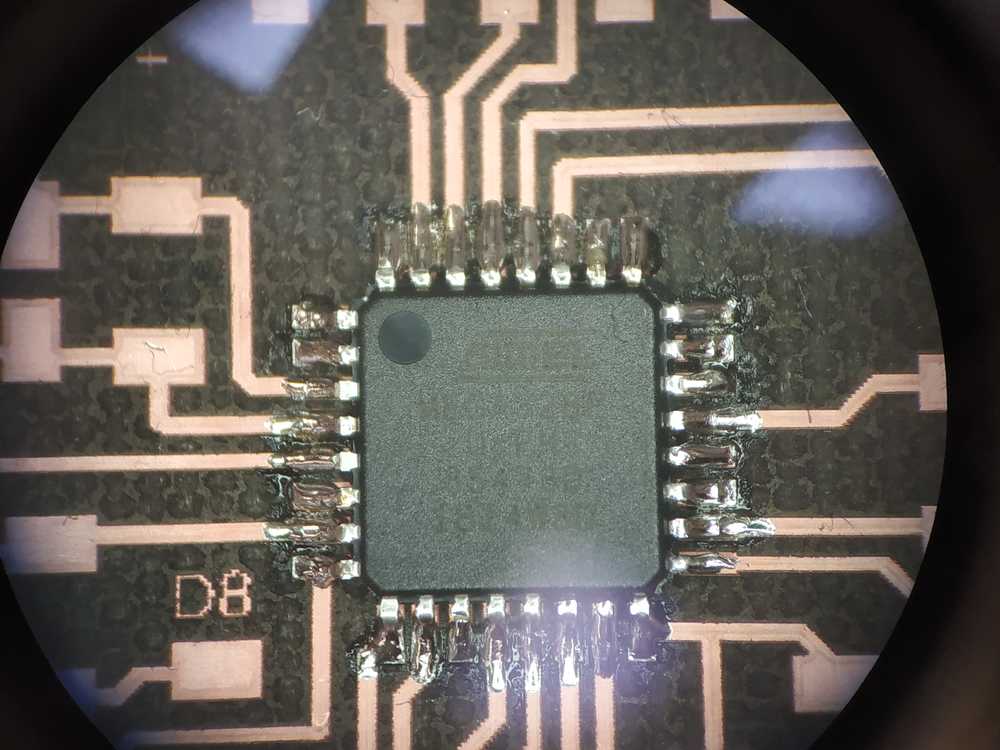
I cheked the connections and soldering using the multimmeter and the microscope.
Everything seemed good so I plugged it to my arduino board to burn the bootloader.
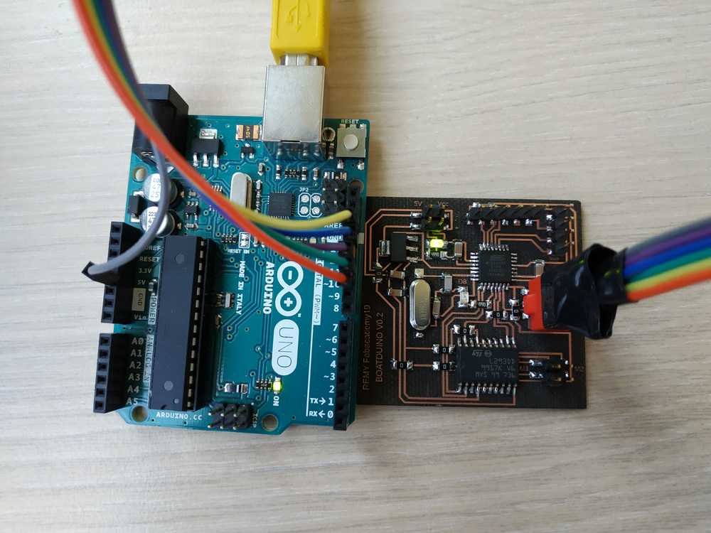 |
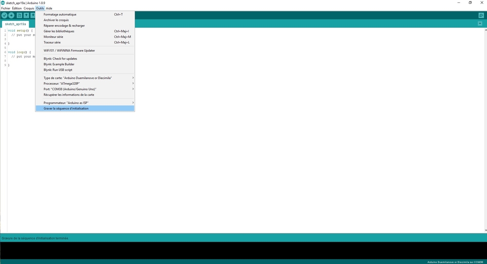 |
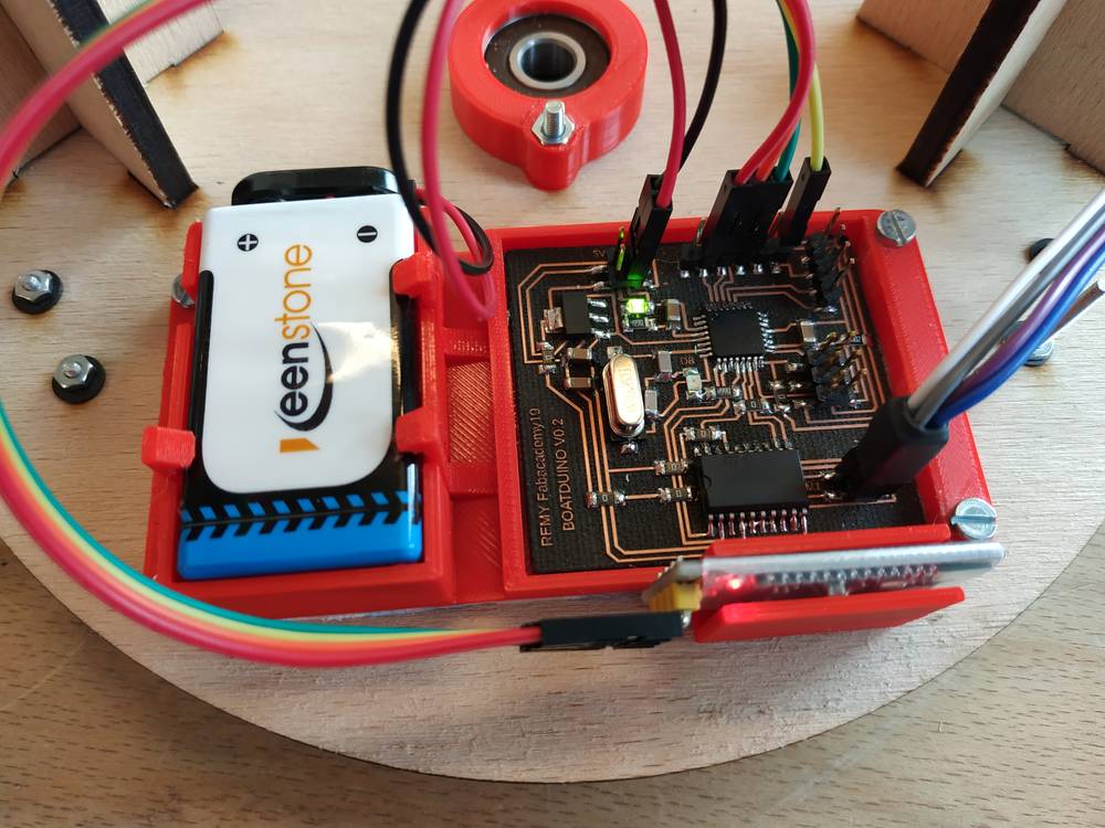
Here I have a board where I can plug a bluetooth module on it and directly control two dc motors.
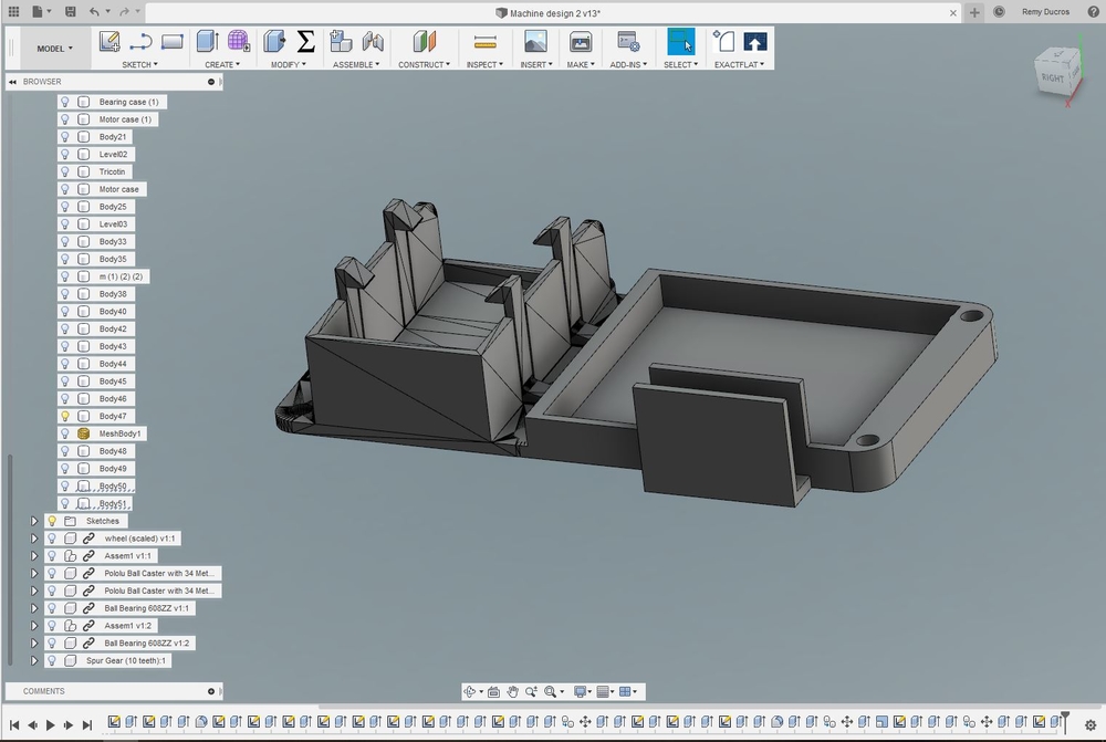
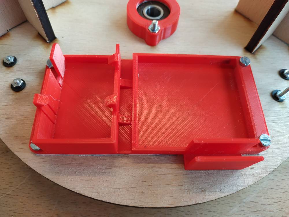
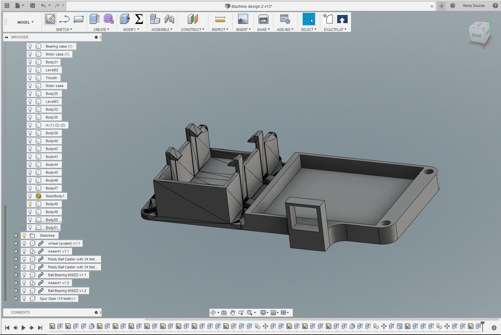
Installation
To fit everything (PCB, battery and bluetooth module) in the machine, I’ve designed a case that I 3D printed.
 |
 |
Here’s how I wired everything.
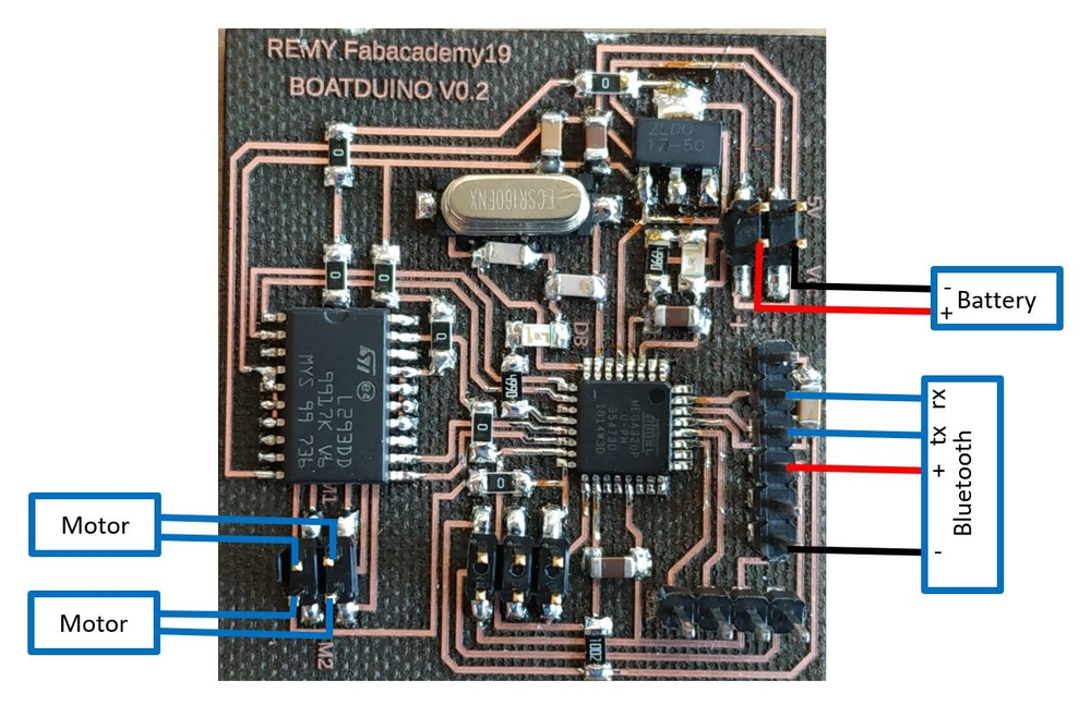
I’ve used zip ties and heat-shrinkable sheath to fit everything properly
 |
|
NOTE : You’ll need two M3x12 screws, two M3x16 screws, 4 M3 washers and four M3 nuts to assemble the case on the platform.
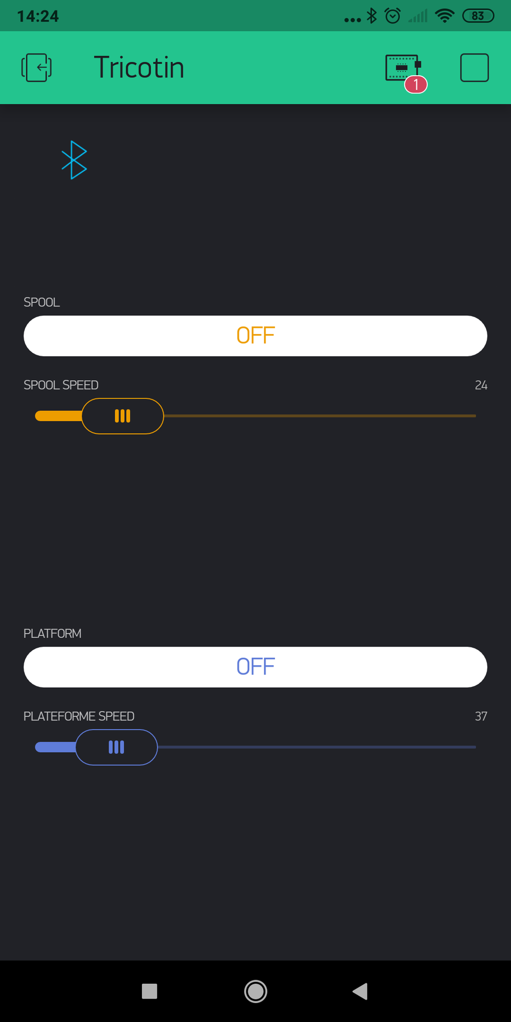
User interface
We want to control the speed of each motor but as the actuator are on a moving platform we have to do it remotly. During the Interface and application programming week, I’ve used blynk to control my project via bluetooth. I did the same here.
Here are the features I wanted in my app :
- ON/OFF button for each motor
- A slider to control the speed of each motor
Here’s how I setup the app in Blynk :
 |
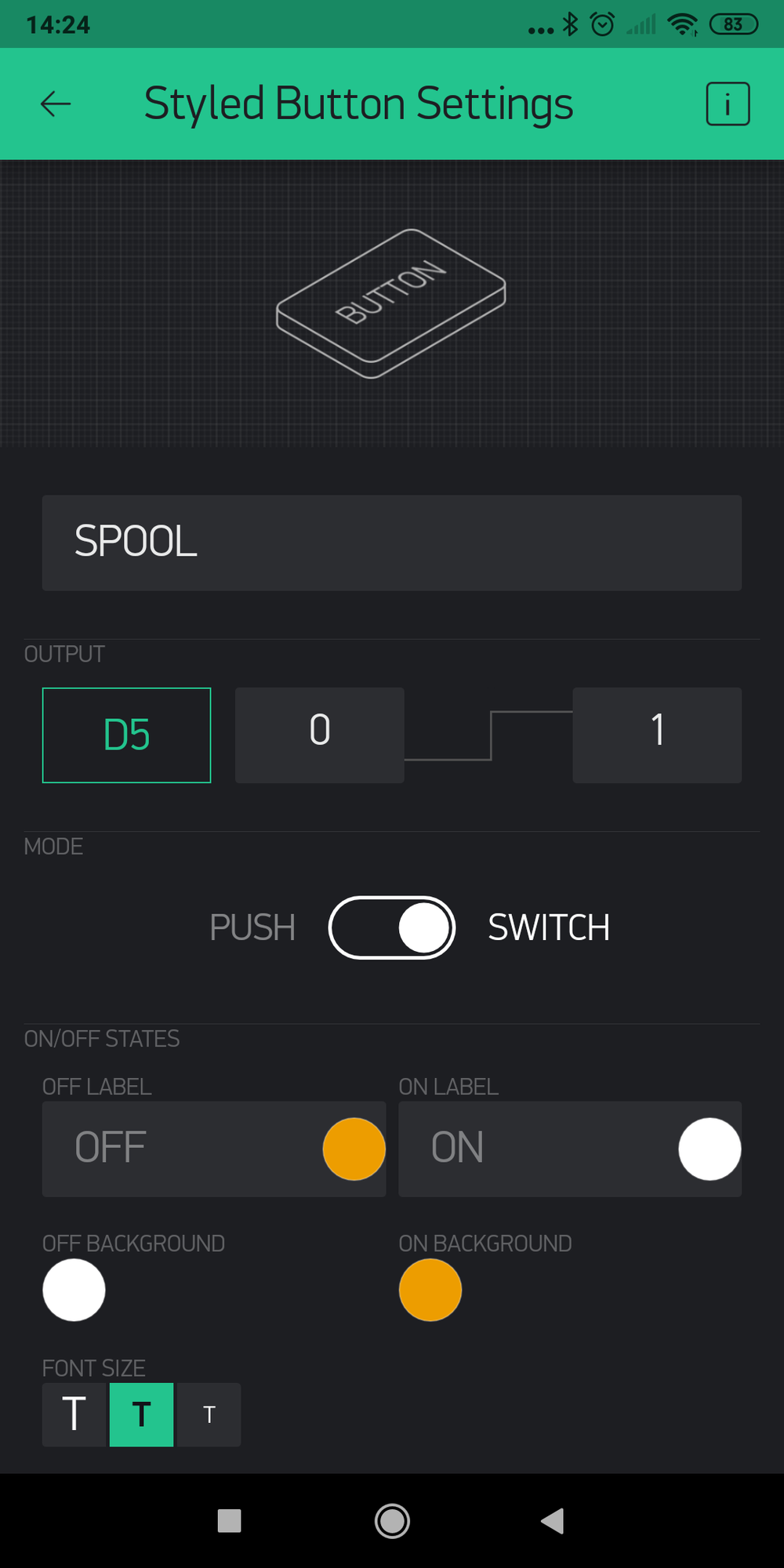 |
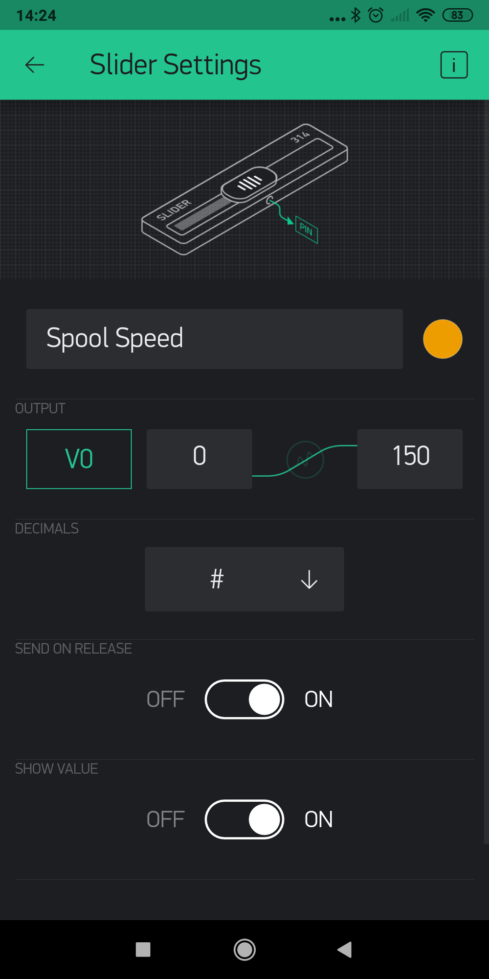 |
For the ON/OFF button I just had to configure one output of the configuration pin of the H-bridge to enable the motor and make it start. To control the speed however, I had to create a virtual pin and refer to it to send a PWM command to my microcontroller.
Here’s the code I’ve made :
const int controlPin1 = 5; // connected to pin 7 on the H-bridge
const int controlPin2 = 12; // connected to pin 2 on the H-bridge
const int enablePin = 6;   // connected to pin 1 on the H-bridge
int motorEnabled = 0; // Turns the motor on/off
int motorSpeed = 0; // speed of the motor

const int controlPin3 = 9; // connected to pin 7 on the H-bridge
const int controlPin4 = 11; // connected to pin 2 on the H-bridge
const int enablePin2 = 10;   // connected to pin 1 on the H-bridge
int motor2Enabled = 0; // Turns the motor on/off
int motor2Speed = 0; // speed of the motor

#define BLYNK_USE_DIRECT_CONNECT
// You could use a spare Hardware Serial on boards that have it (like Mega)
#include <SoftwareSerial.h>
SoftwareSerial DebugSerial(2, 3); // RX, TX

#define BLYNK_PRINT DebugSerial
#include <BlynkSimpleSerialBLE.h>

// You should get Auth Token in the Blynk App.
// Go to the Project Settings (nut icon).
char auth[] = "4ffc1cdc209e4059952419e62f82ba02";

void setup()
{
  // Debug console
  DebugSerial.begin(9600);

  DebugSerial.println("Waiting for connections...");

  // Blynk will work through Serial
  // 9600 is for HC-06. For HC-05 default speed is 38400
  // Do not read or write this serial manually in your sketch
  Serial.begin(9600);
  Blynk.begin(Serial, auth);

    // initialize the inputs and outputs
  pinMode(controlPin1, OUTPUT);
  pinMode(controlPin2, OUTPUT);
  pinMode(controlPin3, OUTPUT);
  pinMode(controlPin4, OUTPUT);
  pinMode(enablePin, OUTPUT);
  pinMode(enablePin2, OUTPUT);

  // pull the enable pin LOW to start
  digitalWrite(enablePin, LOW);
  digitalWrite(enablePin2, LOW);

  // turn on a motor
    digitalWrite(controlPin1, LOW);
    digitalWrite(controlPin2, LOW);

    digitalWrite(controlPin3, LOW);
    digitalWrite(controlPin4, LOW);

}

    BLYNK_WRITE(V0)  // Slider widget - this function gets called every time slider is moved.
{
  int slideValue = param.asInt();  // Get the slider value.
  analogWrite(enablePin, slideValue);  // Send value to digital pin
}

    BLYNK_WRITE(V1)  // Slider widget - this function gets called every time slider is moved.
{
  int slideValue = param.asInt();  // Get the slider value.
  analogWrite(enablePin2, slideValue);  // Send value to digital pin
}

void loop()
{
  Blynk.run();
}
Tests
First I tested everything without load and it worked fine :
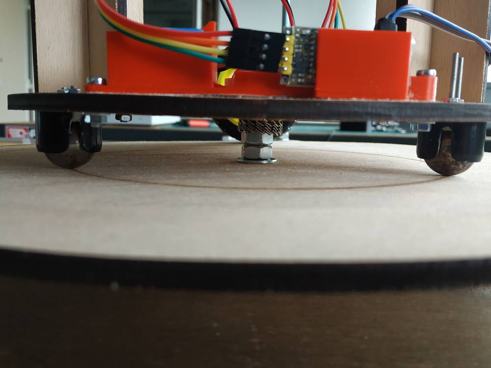
Then, when I placed the platform it wasn’t moving as expected. Few possible reasons for that :
- The PCB couldn’t deliver enough current for the motors to start
- The motor didn’t have enough torque
- The battery was maybe low
- The wheels and balls created a too big resistance on wood so the required force to move was too big
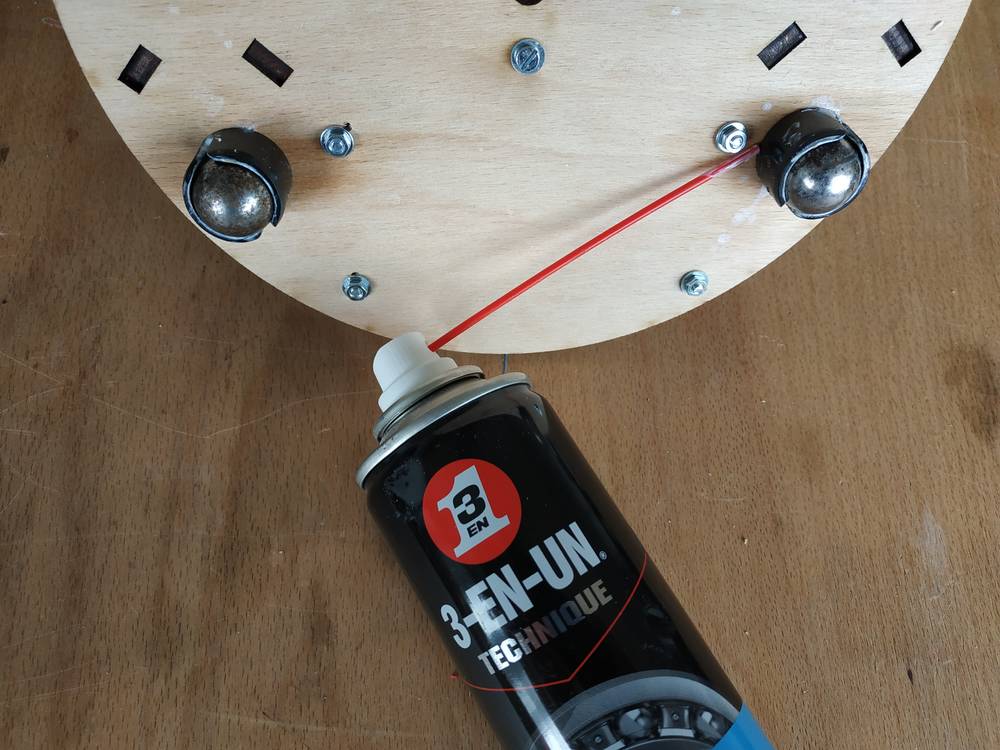
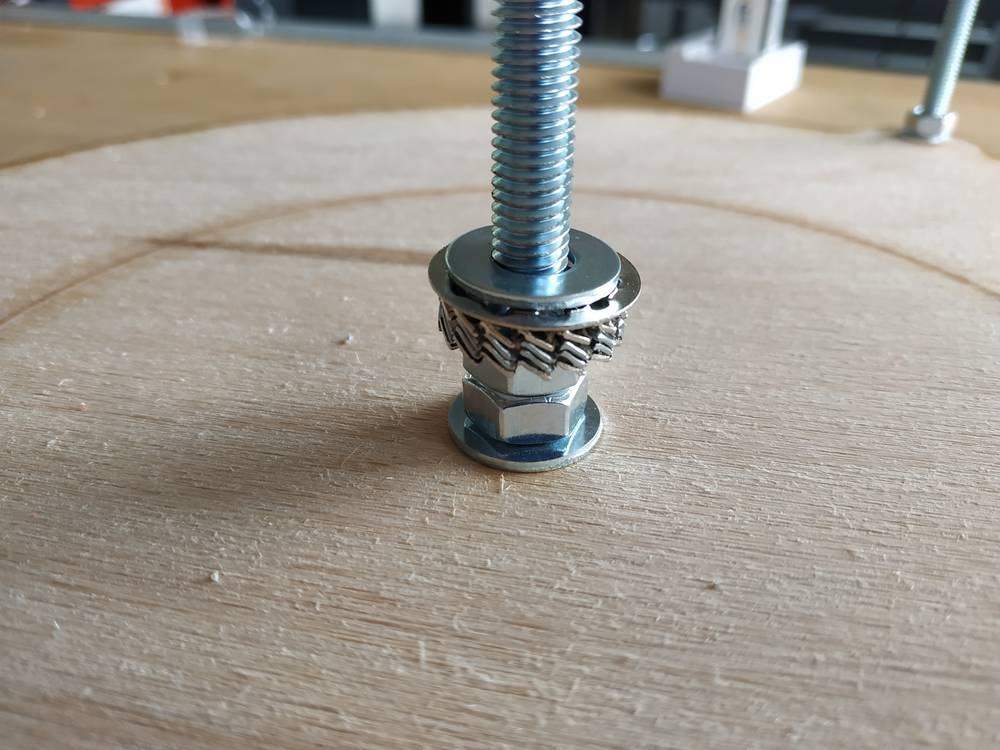
After a day of reflection I did the following :
- I put a new battery
- I lubricate the balls
- I put washers so the balls will have less resistances with the platform
 |
 |
 |
Then it worked fine :
NOTE : It seems to work but the problem is that I don’t have enough controls on the speed of each motor. I could observe two things :
- It’s difficult for the motors to start and when they do, they do it on a certain speed (two much speed for the shaft)
- It’s difficult to have consistant speed. We have variations per rotation or we can see the speed slowly decrease
This issues can be fix :
- by adding encoders to each rotation to control the machine in a closed loop
- by adding a reductor so the machine will go slower but with a higher torque
- by changing the motors to a more powerful on or a stepper motor
- by changing wood to a smoother surface
The knitting system
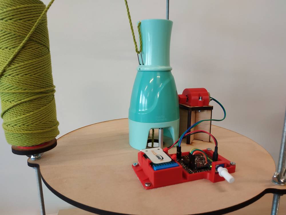
Actuation
For this level based on Camille’s work, we’ve put another DC motor to actuate the knitting machine.
Automation
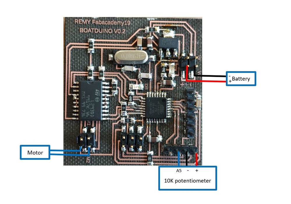
Here the platform is not moving so we can put a pcb to control the motor and a potentiometer to control the speed of the motor.
PCB
I’ve used the same PCB as before, I made a second one for this level.
FUN FACT : After making the PCB using the lasercutter, I’ve checked the connections using a multimeter and found there was a bridge between two lines. I checked on the microscope and see this small bridge.
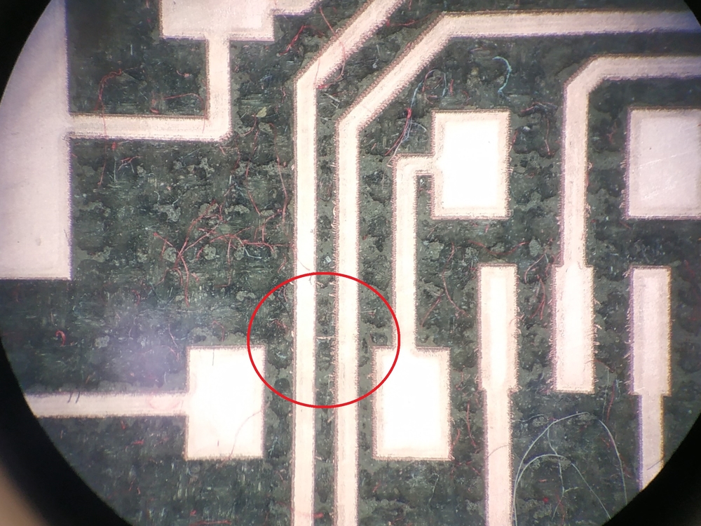
For information each line is 0.3mm width so the bridge is very small yet big enough to create a connection between two lines. After cutting it with a small blade everything was fine again and I had my second PCB.
Code
I made a code to control the speed of the motor using a 10K potentiometer.
const int controlPin1 = 9; // connected to pin 7 on the H-bridge
const int controlPin2 = 11; // connected to pin 2 on the H-bridge
const int enablePin = 10;   // connected to pin 1 on the H-bridge
int motorEnabled = 0; // Turns the motor on/off
int motorSpeed = 0; // speed of the motor
int potPin = A5;// Pin of the potentiometer

void setup() {
  // initialize the inputs and outputs
  pinMode(controlPin1, OUTPUT);
  pinMode(controlPin2, OUTPUT);
  pinMode(enablePin, OUTPUT);

  // pull the enable pin LOW to start
  digitalWrite(enablePin, LOW);
}

void loop() {

  // read the value of the pot and divide by 4 to get a value that can be
  // used for PWM
  motorSpeed = analogRead(potPin) / 4;


  // turn on a motor
    digitalWrite(controlPin1, HIGH);
    digitalWrite(controlPin2, LOW);

    // PWM the enable pin to vary the speed
    analogWrite(enablePin, motorSpeed);

}
Installation
To fit everything (PCB, battery and potentiometer) in the machine, I’ve designed a case that I 3D printed.
 |
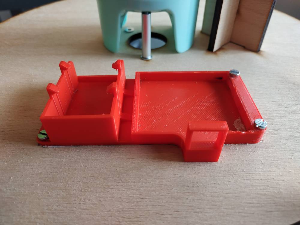 |
Here’s how I wired everything.
I’ve used zip ties and heat-shrinkable sheath to fit everything properly.
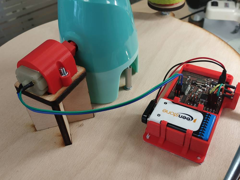 |
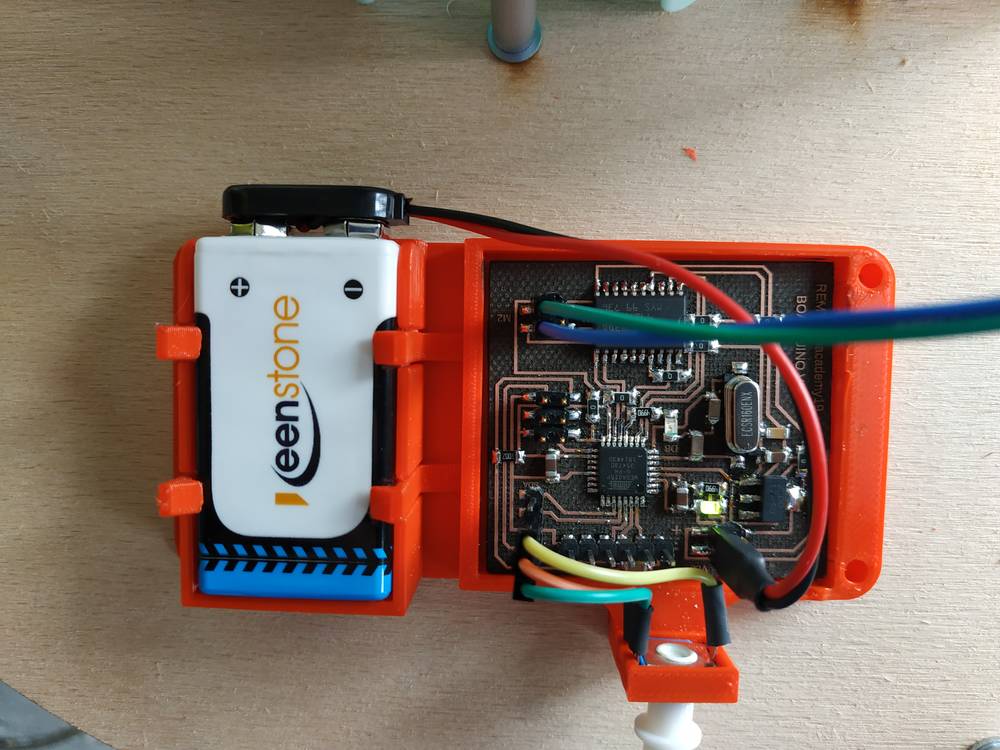 |
NOTE : You’ll need two M3x12 screws, two M3x16 screws, 4 M3 washers and four M3 nuts to assemble the case on the platform.
Tests
My first test was to check if I could control the motor with the potentiometer and it worked fine.
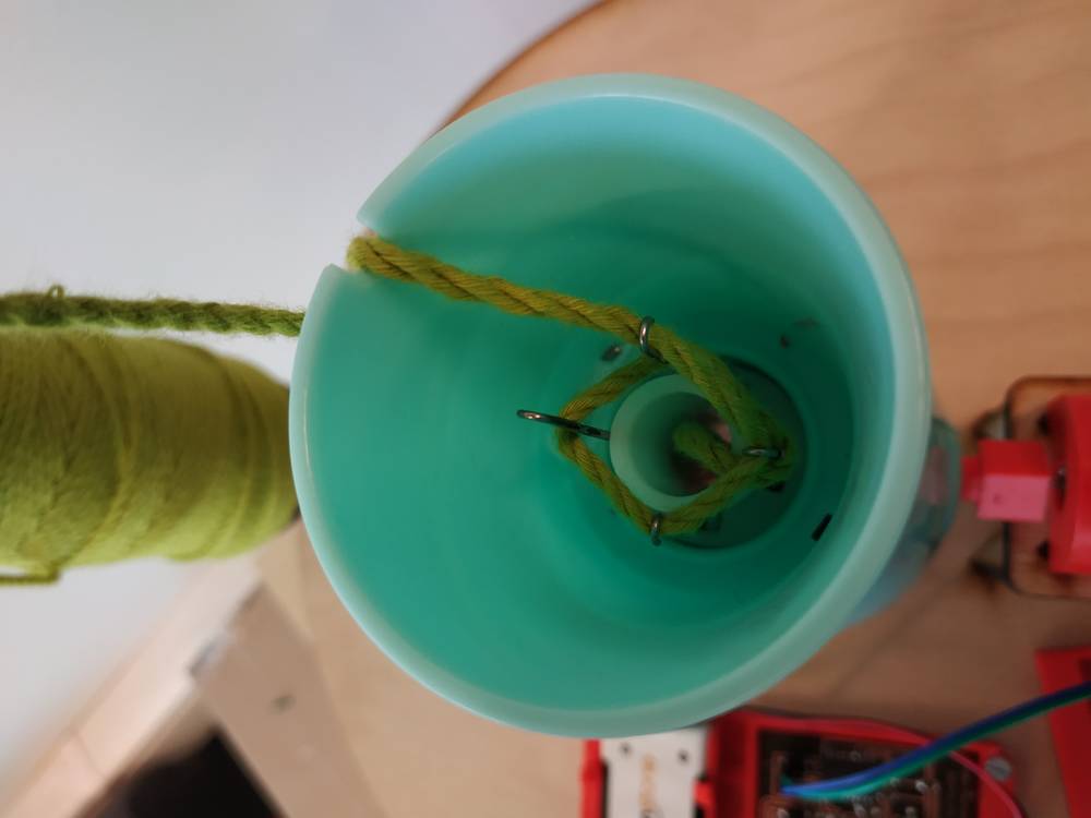
When I plugged the motor to the machine, I could see some mechanical constraints. The result was that the motor needed mor energy to rotate. It worked but it’s difficult to tune it so it goes slow.
Also once we put the yarn in the machine we can feel that the mecanical constraint is even greater. I didn’t manage to make it work with the yarn.
Conclusion
These two weeks were a good effort to start making the machine. I’m glad I could implement the technical solutions I had in mind. I wish I had more time to adjust my design to make the whole thing work. Camille will continue working on the machine based on what we’ve done.
What’s working
- The whole design of the machine is modular
- The whole machine can be made using tools available in the fablab
- The whole machine is made with standard parts
- The platform is working as expected and remotly controlled via a bluetooth app
- The knitting system has been motorised
- We have done all the parts including the PCB
Possible improvements
- Change the material of the first level to have a smoother surface or the platform to move on
- Change the DC motors of the shaft and knitting machine to motoreductors to have higher torque and lower rotation speed
- Add encoders to each rotation to control the machine in a closed loop
- Find a way for both PCB to communicate to synchronize all the motors

Ce(tte) œuvre est mise à disposition selon les termes de la Licence Creative Commons Attribution - Pas d’Utilisation Commerciale - Partage dans les Mêmes Conditions 4.0 International.