Networking and Communications
Introduction
This week our assignments are the following:
•individual assignment:
design, build, and connect wired or wireless node(s)
with network or bus addresses
•group assignment:
send a message between two projects
For this week I decide to make serial bus boards and test them.
Before starting this week assignement I have to learn more about networking protocols,
communication processes,
serial and parallel communications, etc.
Communication
protocol is a digital language through which we communicate with others on the
Internet.
It is a set of rules followed by the network, which defines communication between two or
more devices over a network.
They define rules and conventions for communication.
Network protocols must be confirmed and installed by the sender and receiver to ensure
network\data communication.
It also applies software and hardware nodes that communicate on a network.
There are different
types of network protocols.
• TCP
• IP
• HTTP
• Ethernet
• FTP etc.
Multiple protocols often describe different aspects of a 1 communication. A group of
protocols designed to work together are known as a protocol suite, when implemented in
software they are a protocol stack.
Internet communication protocols are published by the Internet Engineering Task Force
(IETF).
The IEEE handles wired and wireless networking, and the International Organization for
Standardization (ISO) handles other types. The ITU-T handles telecommunication protocols and
formats for the public switched telephone network (PSTN).
As the PSTN and Internet converge, the standards are also being driven towards convergence.
Embedded electronics is all about interlinking circuits to create a symbiotic system. In
order for those individual
circuits to swap their data, they must share a common communication protocol. A lot of
communication protocols have been defined to achieve this data exchange, and, in general,
each can be separated into one of two categories parallel and serial.
This is an example of serial communication
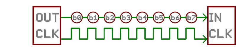
Serial interfaces stream their data, one single bit at a time.
These interfaces can operate on as little as one wire, usually no more than four.
Asynchronous serial communication is a form of serial communication in which the
communicating endpoints' interfaces aren't continuously synchronized by a common clock
signal. Instead of a common synchronization signal, the data stream contains synchronization
information in form of start and stop signals, before and after each unit of transmission,
respectively. The start signal prepares the receiver for arrival of data and the stop signal
resets its state to enable triggering of a new sequence.
This is an example of parallel communication
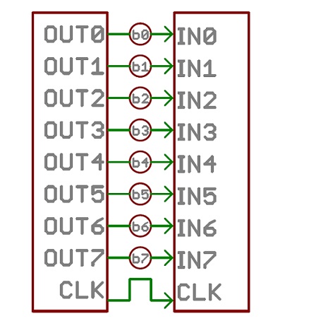 Parallels transfer multiple bits at the same time.
They usually require buses of data transmitting across eight and more wires.
Parallel buses are still used in some applications. But with high-speed data so common
today, a serial interface is the only practical option for communications over any distance
greater than several feet.
Parallels transfer multiple bits at the same time.
They usually require buses of data transmitting across eight and more wires.
Parallel buses are still used in some applications. But with high-speed data so common
today, a serial interface is the only practical option for communications over any distance
greater than several feet.
In telecommunication and data transmission, serial communication is the process of sending
data one bit at a time, sequentially, over a communication channel or computer bus. This is
in contrast to parallel communication, where several bits are sent as a whole, on a link
with several parallel channels.
Serial buses are becoming more common even at shorter distances, as improved signal
integrity and transmission speeds in newer serial technologies have begun to outweigh the
parallel bus's advantage of simplicity and to outstrip its disadvantages .
Network topology has different classifications: Bus, Mesh, Point-to-Point, Hybrid,etc.
Each node in this topology connects to 1 cable. This cable is essentially the spine of the
network.
Data is sent through either side of the cable and into the device, where device either
ignore the data or accept it.
This is considered inexpensive due to there being only one cable, but this can make it
extremely detrimental to the
company if it were to fail as it is the only wire connecting the different computing
devices.
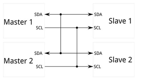
"Master" is a device or a process, which always controls other devices or processes. "Slave"
is a process or a device,
which controls by others ("master"). Once the "master"and "slave" connection is established,
the direction of control is always from the "master" to the "slaves".
"Master" device sends the data (and updates of the data) to slave devices. The
"slave" can only receive it and inform the master about the receiving the data.
The "slave" doesn't have any control to stop receiving the data.
The difference of them is the "master" can operate independently and the slave is dependent on
the 'master".
Many communication systems were generally designed to connect two integrated circuits on the
same printed circuit board, connected by signal traces on that board.Integrated circuits are
more expensive when they have more pins. To reduce the number of pins in a package, many ICs
use a serial bus to transfer data when speed is not important. Some examples of such
low-cost serial buses include RS-232, I²C,etc.
One of the oldest serial interfaces is generically called RS-232.
It is best for short-distance low-speed requirements. It is simple and low cost, and plenty
of components like line drivers and receivers, UARTs, and connectors are available to build
the interface.
The RS-232 standard was defined as a single-ended standard for increasing
serial-communication distances at low baud rates (20kbps). Over the years the standard changed
to accommodate
faster drivers like the MAX3225E, which offers 1Mbps data-rate capability. For RS-232
compliance, a transceiver
such as the MAX3225E must meet the electrical specifications listed down bellow.
A typical RS-232 signal (CH1) swings positive and negative. Note the relative location of the 0V
trace markers on the
left axis. Although the RS-232 data is inverted, an overall translation from TTL/CMOS to RS-232
and back to TTL/CMOS
restores the data's original polarity. Typical RS-232 transmissions seldom exceed 100 feet for
two reasons. Firstly,
the difference between transmitted levels (±5V) and receive levels (±3V) allows only 2V of
common-mode rejection.
Secondly, the distributed capacitance of a longer cable can degrade slew rates by exceeding the
maximum specified load (2500pF).
Because the RS-232 was designed as a point-to-point rather than multidrop interface, its drivers
are specified for single loads
from 3kΩ to 7kΩ. Therefore, a daisy-chain scheme is typically implemented for multidrop
interface applications.
The main purpose of a serial interface is to provide a single path for data transmission
wirelessly or over a cable.
More information about RS-232 you can download
Useful to read
• Serial communication parameters
• Asynchronous communication methods
• RS-232
• Common network protocols and their ports
Step 1 - Make the boards
I downloaded serial bus board make files and prepared them for cutting process.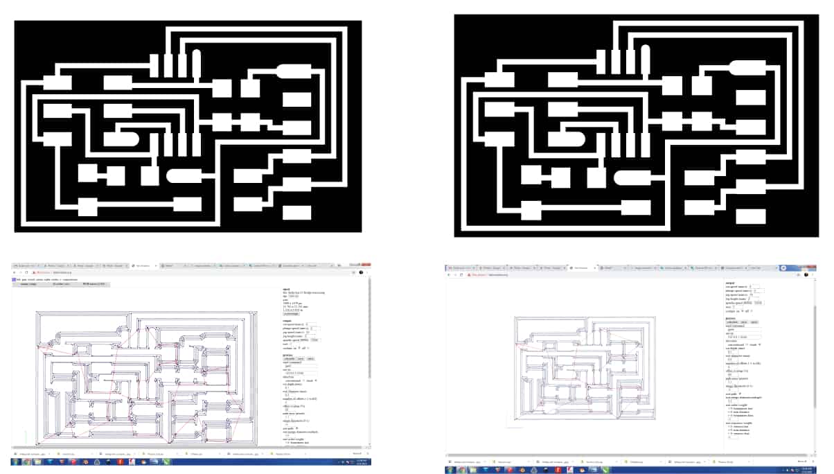
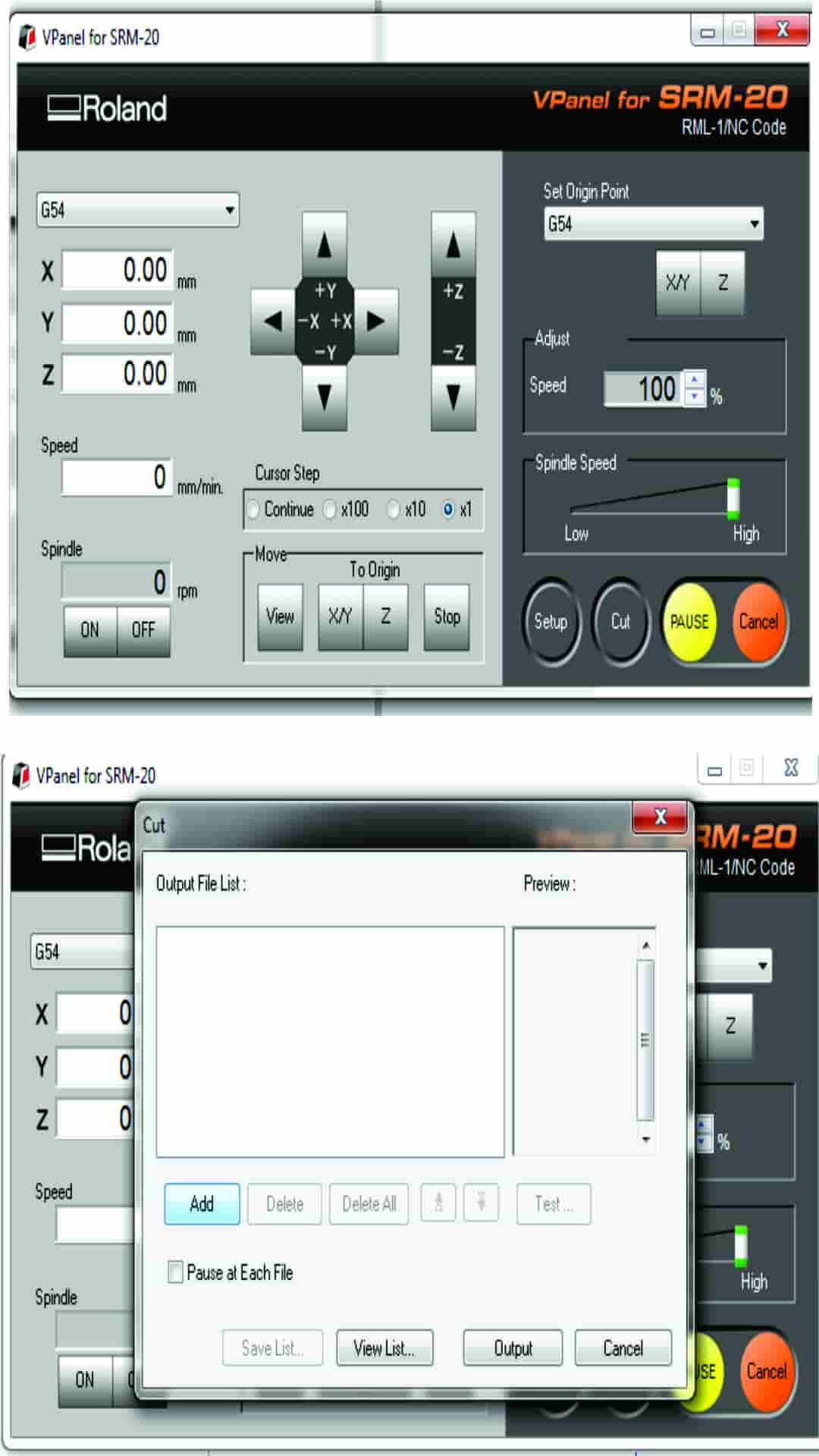
Setting up the machine
• Turn on the machine
• Put the material in the machine, fixed it with double sided stick
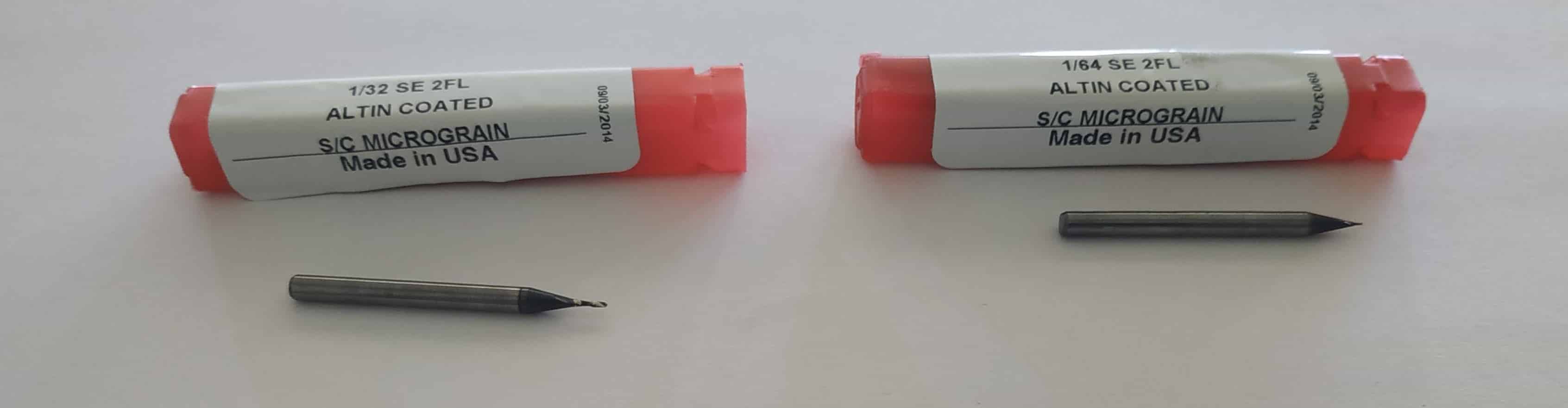
• Attached end mill 1/64 for milling traces Repeated the standart actions for Srm-20 milling machine(x-0, y-0, z-0), put the board on the table of the machine.
• Opened fab modules and upload my files there, then saved
• Setted the origin point chose"Machine Coordinate System" in our case I will use "G54" and "G55" that's the first 2 of 6 Work Coordinate Systems. During this process I used Vpanel pointers "right" "left" "up" "down"
• Went back to fab modules and chose image "png"- Gcode "nc"-PCB traces "1/64" - "selected calculate" - "save".
When the files had been saved I sent them to machine for cutting. Started the cutting process and paused to check how it was going on. For cutting out the boards I opened fab modules chose image "png"- Gcode "nc"-PCB interior "1/32" - "selected calculate" - "save". Then I cleaned the board and started soldering process.
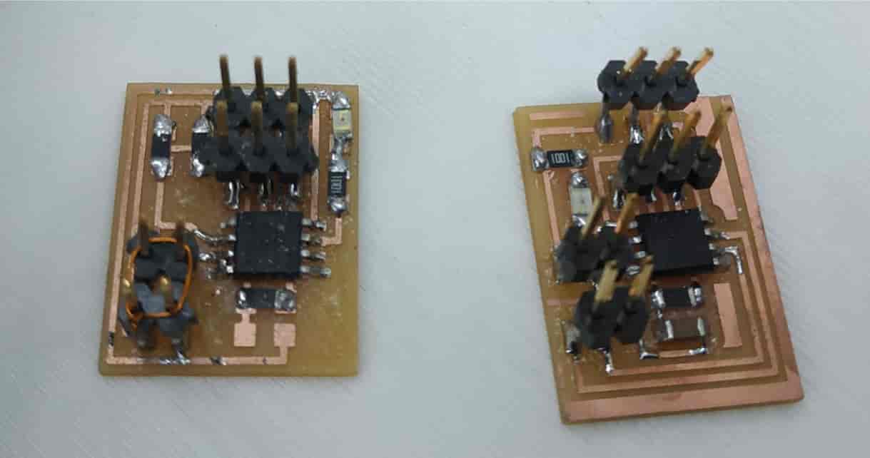
During the soldering process I made some mistakes and had to solder some parts again. In the photo above you can see the mistakes.
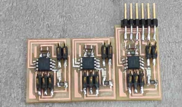
This the final soldered boards and already conected.
I used the following components for the boards
• ATtiny 45 microcontroller
• 1k SMD resistor
• 10k SMD resistor
• SMD LED
• 1uF SMD capacitor
• pin headers
Bridge board had male pin headers for Fab ISP, male pin headers for power and com, pinheader FTDI cabel and the node had only male pin headers for Fab ISP, male pin headers for power and com.
Step 2 - Programming
For programming board I used Fab ISP and FTDI cabel for serial communicate.Connect your usbtiny (Fab ISP) to the hello.bus.45.bridge board's Fab ISP port using the Fab ISP cable, connect FTDI cable to board's FTDI pins and connect FabISP to the USB port of the computer.In order to program board I need
• FTDI cable to communicate
• Need to be installed "avrdude" and "avr-gcc"
• Fab ISP with ISP cable
• Codes (on .c ) and makefiles from Neil's website
cd to network folder and enter make -f hello.bus.45.make program-usbtiny command.
-f scecifies the makefile's name in this case it's "hello.bus.45.make" program- specifies the programmer we're going to use in our case "usbtiny"
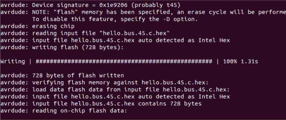
Overall this command makes the " .hex " file based on the libraries and the C code. If everything goes right we should see the message. After type avrdude -p t45 -P usb -c usbtiny -U flash:w:hello.bus.45.c.hex -p scecifies the AVR device in our case t45 (ATtiny45) -P specifies the connection port in our case USB port (ISP) -c specifies the programmer type in our case it's usbtiny .
-U specifies a memory operation (multiple options available) "flash" flashes the ROM, "w" reads the .hex file and writes it to the memory.
If everything goes right you should see this message. Close the terminal.
Here is the makefile I used
and "C" code
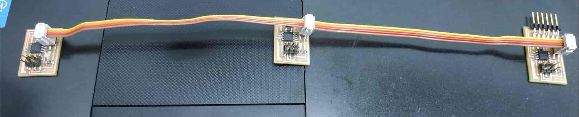
In order to make connection between bridge and nodes we to make 4 wire ribbon cable about 30cm and 4 2x2 connectors. Now find the #define node_id '0' line in the C code and change '0' to '1' in order to have unique id for each board. Save the file.
Connect our FabISP to the node board's ISP port using the Fab ISP cable as shown in the image above. Again open the "network" folder right click and select "Open in Terminal" option type this command and push enter: -f hello.bus.45.make program-usbtiny.
Next type this command and push enter avrdude -p t45 -P usb -c usbtiny -U flash:w:hello.bus.45.c.hex.
Now find #define node_id '1' line in the C code and change '1' to '2' in order to have unique ID for the next board.
Save the file. Connect our Fab ISP to the next node board's Fab ISP port using the Fab ISP cable as shown in the image below.
Again open the "network" folder right click and select "Open in Terminal" option again type this command nd) and push enter: make -f hello.bus.45.make program-usbtiny.
Next type this command and push enter avrdude -p t45 -P usb -c usbtiny -U flash:w:hello.bus.45.c.hex.Remove the Fab ISP cable.
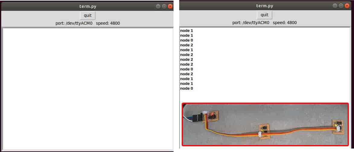
Download term.py to the same "network" folder.
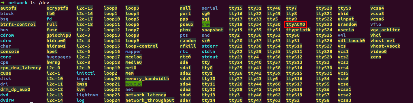
We need term.py to send and monitor serial data. Open the "network" folder right click and select "Open in Terminal". Type this command ls /dev ls /dev and hit enter. This command lists the devices connected. FTDI cable should be "ttyUSB0". Now type this command sudo python term.py /dev/ttyUSB0 9600 push enter
Summarize We have 3 boards, one of them is a "master board", 2 others are nodes (slave boards). Each board has it's own digit 0,1,2. The code gets chr simbol from the computer by FTDI (we call it bridge). The bridge send the chr to all nodes.
while (1) {
get_char(&serial_pins, serial_pin_in, &chr);
flash();
if (chr == node_id) {
output(serial_direction, serial_pin_out);
static const char message[] PROGMEM = "node ";
put_string(&serial_port, serial_pin_out, (PGM_P) message);
put_char(&serial_port, serial_pin_out, chr);
put_char(&serial_port, serial_pin_out, 10); // new line
led_delay();
flash();
input(serial_direction, serial_pin_out);
}
If chr = node id, for example 0, 1 or 2. The "node" blinks when it gets its id.
Code
		//
		//
		// hello.bus.45.c
		//
		// 9600 baud serial bus hello-world
		//
		// Neil Gershenfeld
		// 11/24/10
		//
		// (c) Massachusetts Institute of Technology 2010
		// Permission granted for experimental and personal use;
		// license for commercial sale available from MIT.
		//

		#include
		#include
		#include
		#include

		#define output(directions,pin) (directions |= pin) // set port direction for output
		#define input(directions,pin) (directions &= (~pin)) // set port direction for input
		#define set(port,pin) (port |= pin) // set port pin
		#define clear(port,pin) (port &= (~pin)) // clear port pin
		#define pin_test(pins,pin) (pins & pin) // test for port pin
		#define bit_test(byte,bit) (byte & (1 << bit)) // test for bit set
		#define bit_delay_time 100 // bit delay for 9600 with overhead
		#define bit_delay() _delay_us(bit_delay_time) // RS232 bit delay
		#define half_bit_delay() _delay_us(bit_delay_time/2) // RS232 half bit delay
		#define led_delay() _delay_ms(100) // LED flash delay

		#define led_port PORTB
		#define led_direction DDRB
		#define led_pin (1 << PB0)

		#define serial_port PORTB
		#define serial_direction DDRB
		#define serial_pins PINB
		#define serial_pin_in (1 << PB3)
		#define serial_pin_out (1 << PB4)

		#define node_id '0'

		void get_char(volatile unsigned char *pins, unsigned char pin, char *rxbyte) {
		   //
		   // read character into rxbyte on pins pin
		   //    assumes line driver (inverts bits)
		   //
		   *rxbyte = 0;
		   while (pin_test(*pins,pin))
			  //
			  // wait for start bit
			  //
			  ;
		   //
		   // delay to middle of first data bit
		   //
		   half_bit_delay();
		   bit_delay();
		   //
		   // unrolled loop to read data bits
		   //
		   if pin_test(*pins,pin)
			  *rxbyte |= (1 << 0);
		   else
			  *rxbyte |= (0 << 0);
		   bit_delay();
		   if pin_test(*pins,pin)
			  *rxbyte |= (1 << 1);
		   else
			  *rxbyte |= (0 << 1);
		   bit_delay();
		   if pin_test(*pins,pin)
			  *rxbyte |= (1 << 2);
		   else
			  *rxbyte |= (0 << 2);
		   bit_delay();
		   if pin_test(*pins,pin)
			  *rxbyte |= (1 << 3);
		   else
			  *rxbyte |= (0 << 3);
		   bit_delay();
		   if pin_test(*pins,pin)
			  *rxbyte |= (1 << 4);
		   else
			  *rxbyte |= (0 << 4);
		   bit_delay();
		   if pin_test(*pins,pin)
			  *rxbyte |= (1 << 5);
		   else
			  *rxbyte |= (0 << 5);
		   bit_delay();
		   if pin_test(*pins,pin)
			  *rxbyte |= (1 << 6);
		   else
			  *rxbyte |= (0 << 6);
		   bit_delay();
		   if pin_test(*pins,pin)
			  *rxbyte |= (1 << 7);
		   else
			  *rxbyte |= (0 << 7);
		   //
		   // wait for stop bit
		   //
		   bit_delay();
		   half_bit_delay();
		   }

		void put_char(volatile unsigned char *port, unsigned char pin, char txchar) {
		   //
		   // send character in txchar on port pin
		   //    assumes line driver (inverts bits)
		   //
		   // start bit
		   //
		   clear(*port,pin);
		   bit_delay();
		   //
		   // unrolled loop to write data bits
		   //
		   if bit_test(txchar,0)
			  set(*port,pin);
		   else
			  clear(*port,pin);
		   bit_delay();
		   if bit_test(txchar,1)
			  set(*port,pin);
		   else
			  clear(*port,pin);
		   bit_delay();
		   if bit_test(txchar,2)
			  set(*port,pin);
		   else
			  clear(*port,pin);
		   bit_delay();
		   if bit_test(txchar,3)
			  set(*port,pin);
		   else
			  clear(*port,pin);
		   bit_delay();
		   if bit_test(txchar,4)
			  set(*port,pin);
		   else
			  clear(*port,pin);
		   bit_delay();
		   if bit_test(txchar,5)
			  set(*port,pin);
		   else
			  clear(*port,pin);
		   bit_delay();
		   if bit_test(txchar,6)
			  set(*port,pin);
		   else
			  clear(*port,pin);
		   bit_delay();
		   if bit_test(txchar,7)
			  set(*port,pin);
		   else
			  clear(*port,pin);
		   bit_delay();
		   //
		   // stop bit
		   //
		   set(*port,pin);
		   bit_delay();
		   //
		   // char delay
		   //
		   bit_delay();
		   }

		void put_string(volatile unsigned char *port, unsigned char pin, PGM_P str) {
		   //
		   // send character in txchar on port pin
		   //    assumes line driver (inverts bits)
		   //
		   static char chr;
		   static int index;
		   index = 0;
		   do {
			  chr = pgm_read_byte(&(str[index]));
			  put_char(&serial_port, serial_pin_out, chr);
			  ++index;
			  } while (chr != 0);
		   }

		void flash() {
		   //
		   // LED flash delay
		   //
		   clear(led_port, led_pin);
		   led_delay();
		   set(led_port, led_pin);
		   }

		int main(void) {
		   //
		   // main
		   //
		   static char chr;
		   //
		   // set clock divider to /1
		   //
		   CLKPR = (1 << CLKPCE);
		   CLKPR = (0 << CLKPS3) | (0 << CLKPS2) | (0 << CLKPS1) | (0 << CLKPS0);
		   //
		   // initialize output pins
		   //
		   set(serial_port, serial_pin_out);
		   input(serial_direction, serial_pin_out);
		   set(led_port, led_pin);
		   output(led_direction, led_pin);
		   //
		   // main loop
		   //
		   while (1) {
			  get_char(&serial_pins, serial_pin_in, &chr);
			  flash();
			  if (chr == node_id) {
				 output(serial_direction, serial_pin_out);
				 static const char message[] PROGMEM = "node ";
				 put_string(&serial_port, serial_pin_out, (PGM_P) message);
				 put_char(&serial_port, serial_pin_out, chr);
				 put_char(&serial_port, serial_pin_out, 10); // new line
				 led_delay();
				 flash();
				 input(serial_direction, serial_pin_out);
				 }
			  }
		   }
Here is the result of the testing