Final project / Mechanical part
Introduction
For my final project I need to make a desk using Computer-controlled machining processes(ShopBot), and 3D printing. The aim of this part is to make a beautiful and functional desk, that all electronics can fit inside of it. And also I need to perform 3D and 2D modeling skills, for that I will use Autodesk Inventor Pro.On Computer-controlled machining processes(ShopBot) I must cut the legs of my desk using plywood material, and surface of my desk using MDF material(inside of the surface must fit my 3D block). For 3D printing, I must print boxes for changing coils , each about 100x100mm.
3D modeling
Tools
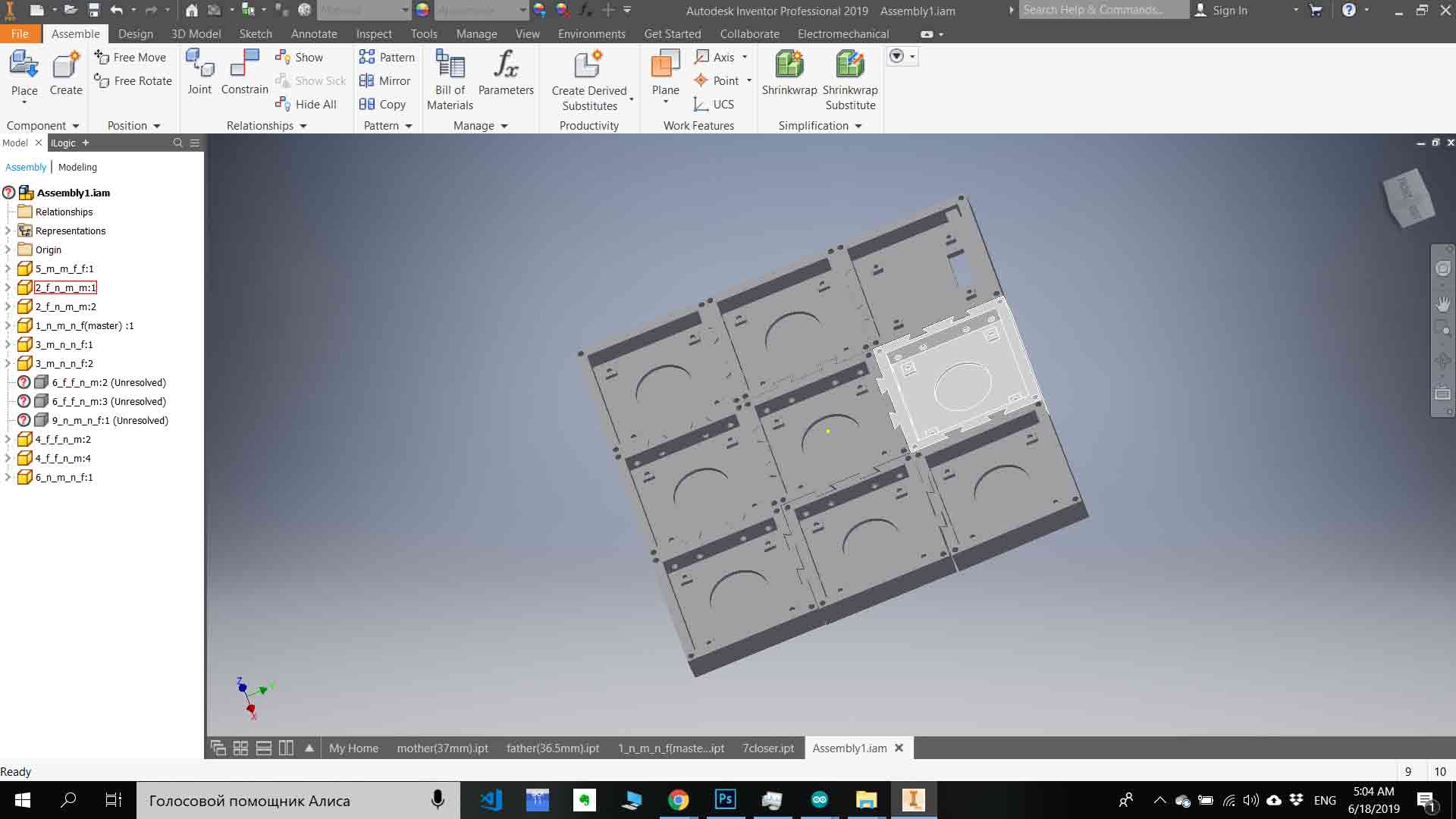
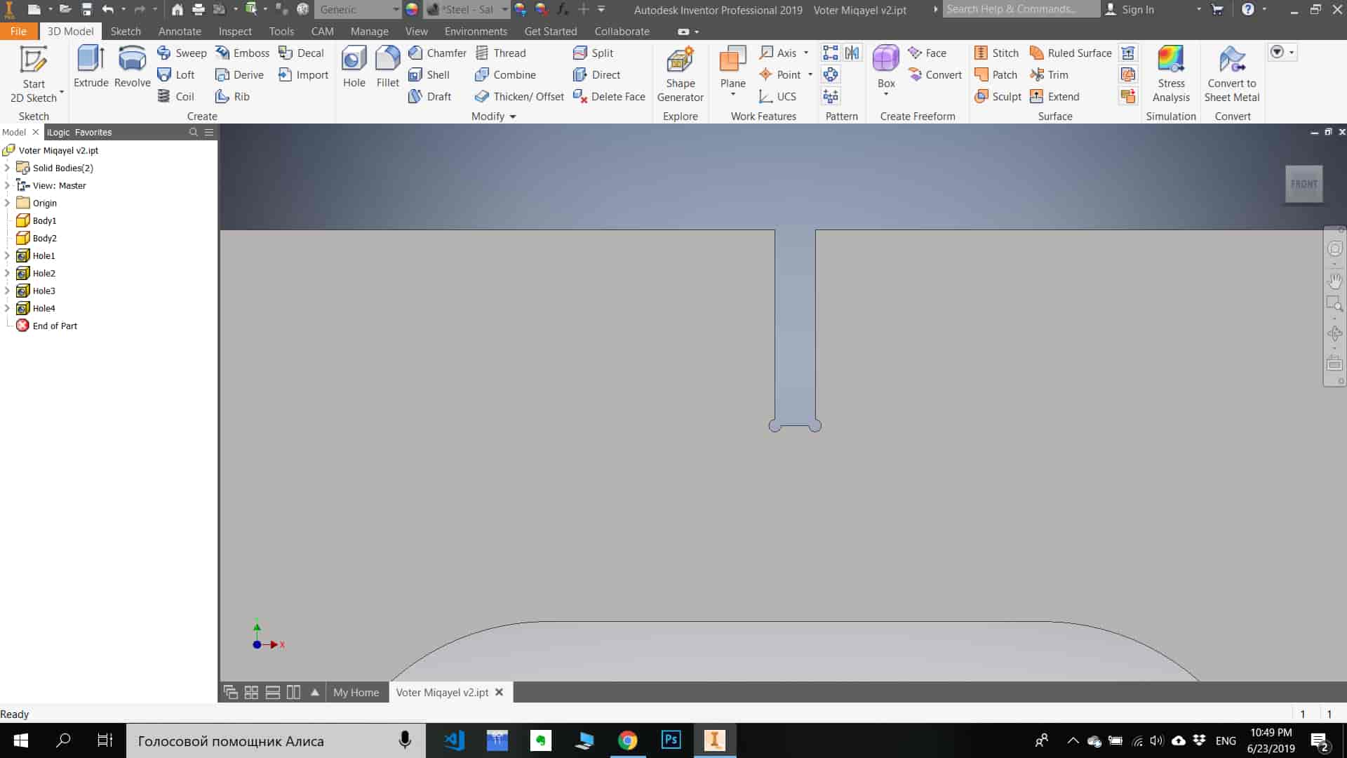
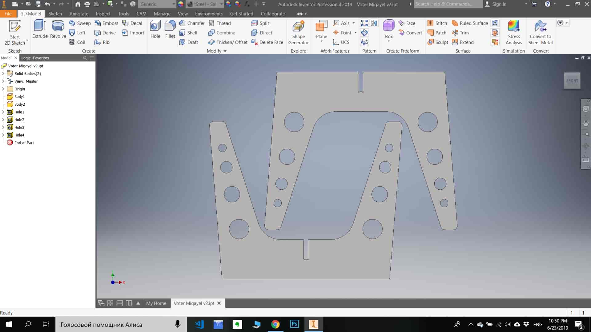
I have created 3D models of all parts of the desk (legs, surface, 3d printing). I have used Autodesk Inventor Pro for 3D printing parts modeling, and for legs and surface modeling I used Fusion 360.Main to that I used in process off modeling
Fill the frameDialog to create over multiple edges selected in the viewport the beams of the type of that previously chosen among those present in the model.Reverse orientationool to spin one object around the "X" axis of its shape by 180 degrees.Insert a curveBeside the common widgets with other "Insert..." dialogs, the Trim/Extend button allow to adjust the length of selected pipes to the selected edge of the curve.Insert a pathool to create a continuous DWire over the path defined by the edges selected in the viewport, even if these are not touching or are intersecting in the middle or belongs to different objects.Quick move objectsTo move quickly any part, to access the underlying objects for instance, this tool provides a graphic handle (green arrow) by clicking on which it's possible to displace and rotate the selected objects.Rotate workplaneRotates the WP around one of its axis. Also in this case a green arrow is displayed in the viewport to identify the present orientation of the WP: the arrow is pointed in the Z direction and the long base of the arrow is layed over the X direction.For more infoClick here .
3D printing parts
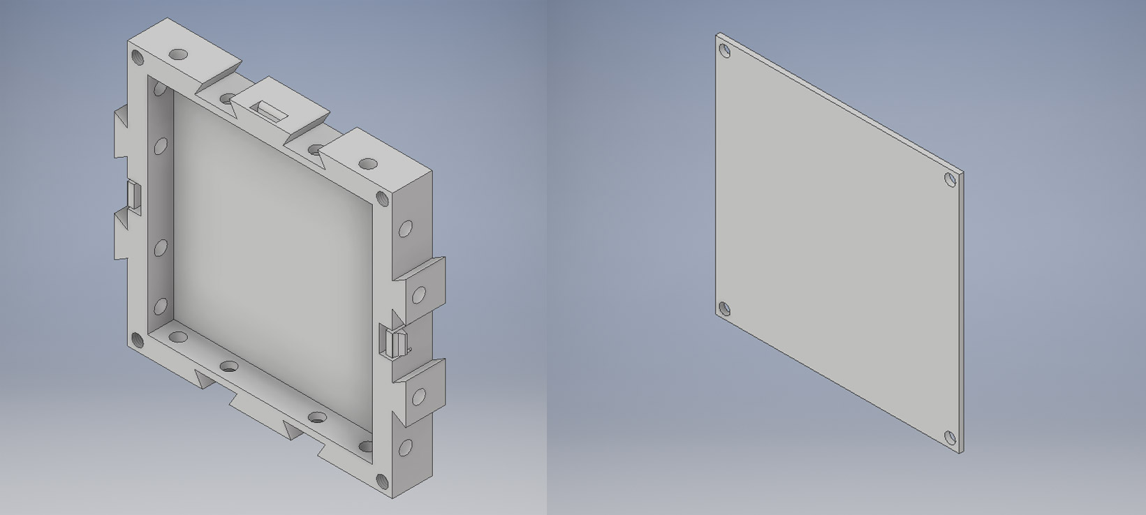
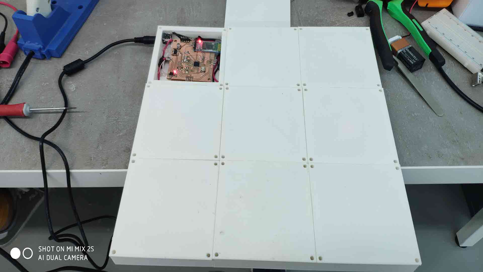
Afterall when I design the desk I have got 7 different parts (similar, but different ). The charging surface is about 300x300mm, and each block is 100x100mm(with different snaping part combinations ), so we have 8 boxes for coil and 1 is a controlling system, a total of 9 boxes.
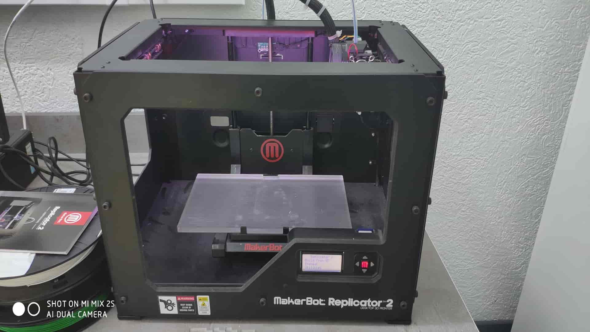
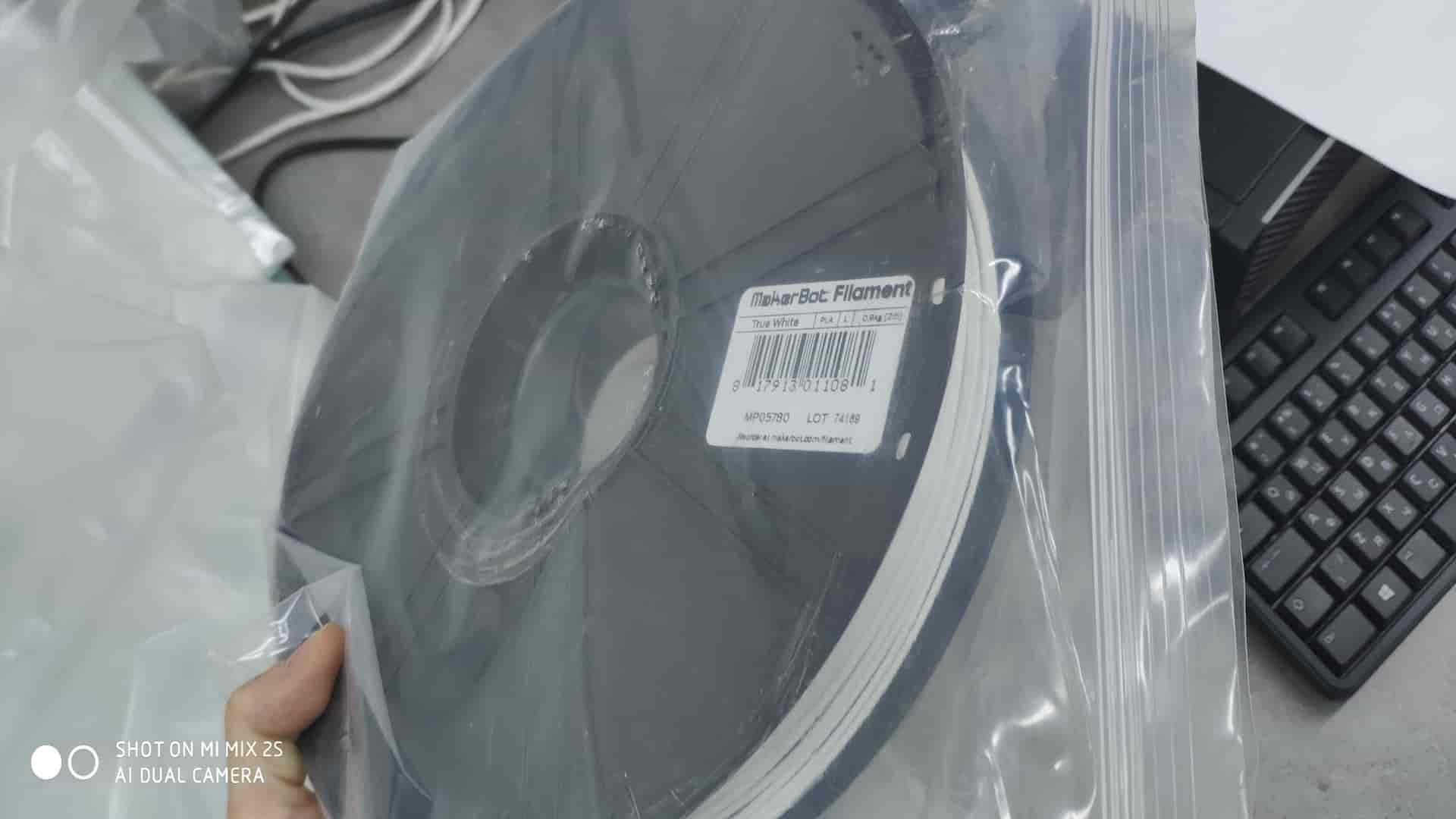
For 3D printing I used Makerbot Replicator 2. As a filament, I used Makerbot Filament “True White, PLA, L, 0.9kg”.After loading filament, I set parameters of printing
After generating an animation with these parameters, the time estimate for printing is 3h 36m(but it printed much faster about 2h), the material needed for printing is about 70,93g.
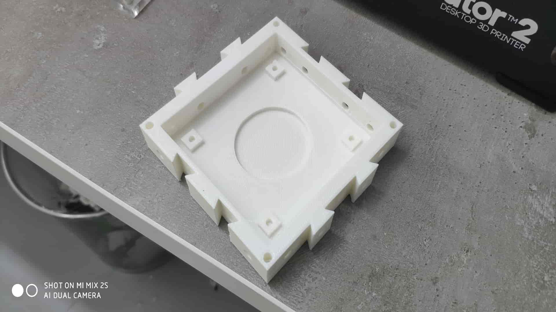
After printing first 2 parts, I tested to fit one into the other (using hammer), and connection between two parts was very strong and I like it because I need my surface to be much more stable.After printing all parts and assembling I get what I wanted 300x300x22,5mm boxes for wireless charging coils.
CAM
Autodesk Inventor is a favorite tool of engineering professionals. To fabricate your Inventor designs on the Bantam Tools Desktop PCB Milling Machine, a few steps are required. Because Inventor is only a design application, an additional CAM (computer-aided manufacturing) application or plugin is required to generate toolpaths and G-code that the milling machine can follow to mill the design. For more information on the overall CAD and CAM process, see our CAD and CAM Guide.
Option 1: Model your part in Inventor, generate toolpaths and G-code from within Inventor using an integrated CAM plugin such as Inventor HSM, and then load the G-code file into the Bantam Tools Desktop Milling Machine Software.
Option 2: Model your part in Inventor, export it as a STEP file, generate toolpaths and G-code from that file in a separate CAM application such as Fusion 360, and then load the G-code file into the Bantam Tools Desktop Milling Machine Software.
Option 1 (using an integrated CAM plugin) is easier, more convenient, and provides a higher-end feature set. It allows you to skip the added steps of exporting a STEP file and loading it into a separate CAM program. The only trade-off is that it’s usually more expensive. However, if you expect to be iterating rapidly and milling a lot of prototypes of your parts, the extra speed and convenience may be worth it. This guide shows the process of generating G-code from Inventor using the Inventor HSM integrated plugin. If you choose to go with Option 2 and use a separate CAM application, this guide also demonstrates the process of exporting a STEP file from Inventor, which you can then import into a CAM application such as Fusion 360. From there, you can generate a G-code file that can be imported into the software and milled on the milling machine.
Steps
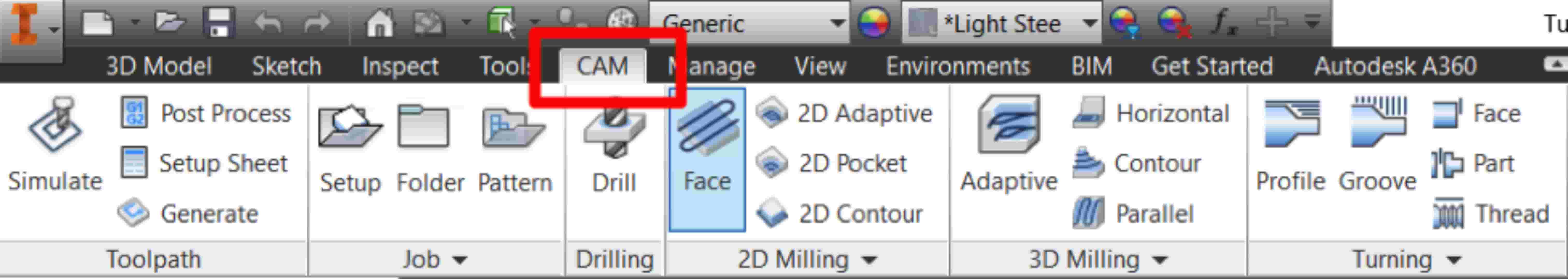
Step 1: Switch to the CAM tab.)Once you’re done modeling your part in Inventor, switch to the CAM tab. The CAM tab contains all the available milling strategies that you can use to mill your part.
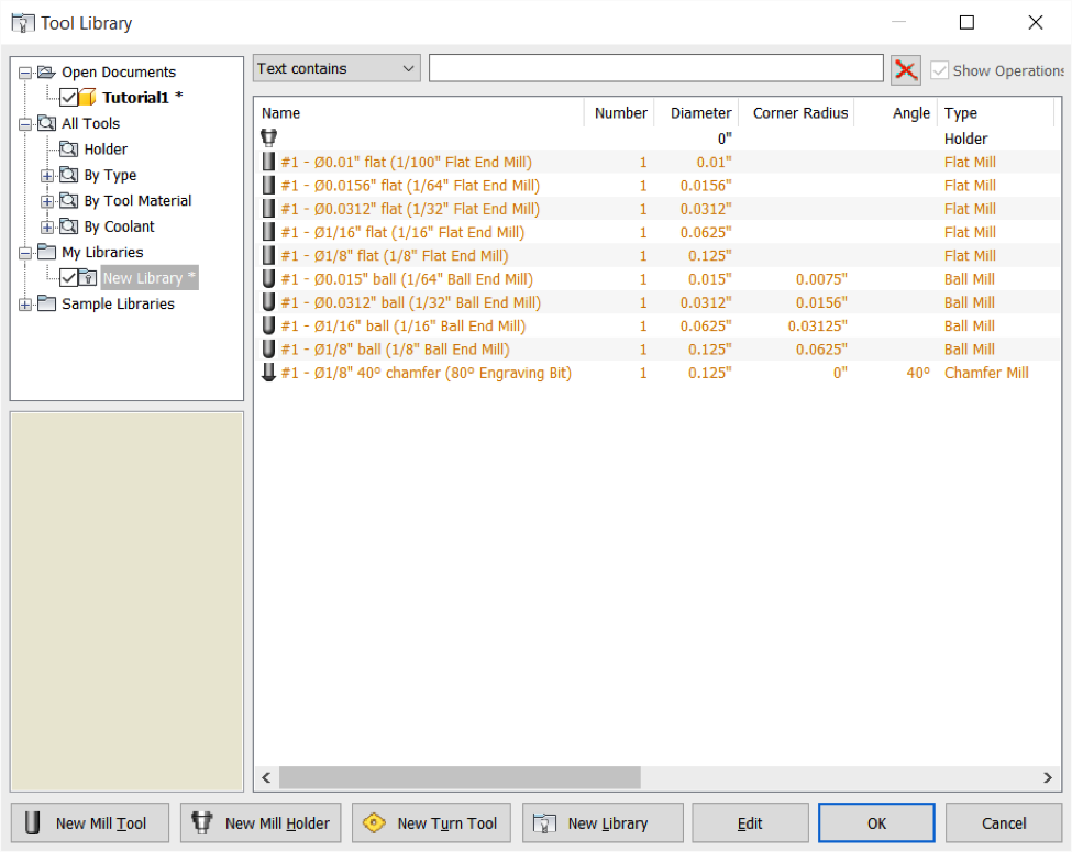
Step 2: Install the Othermill tool library.)The Othermill tool library contains digital versions of all the tools we sell. By accurately representing the geometry of the tools you’ll be using to mill your part, you can produce physical parts that match your digital designs.
Step 3: Choose your machining strategies.)Here's where you decide how you’re going to machine each feature of your part. If you’re new to CAM, there’s a bit of a learning curve. CAM is a pretty deep subject, but each CAM application has tutorials to help you learn how to use it. Here are Autodesk’s Inventor HSM tutorials.
Step 4: Post-process your toolpaths.)Once you’ve generated your toolpaths, you’re ready to post-process them:
OPTION 2: USE A SEPARATE CAM APPLICATION
If you’d prefer to use a separate application for CAM, here’s how to export a file that can be imported into that application.
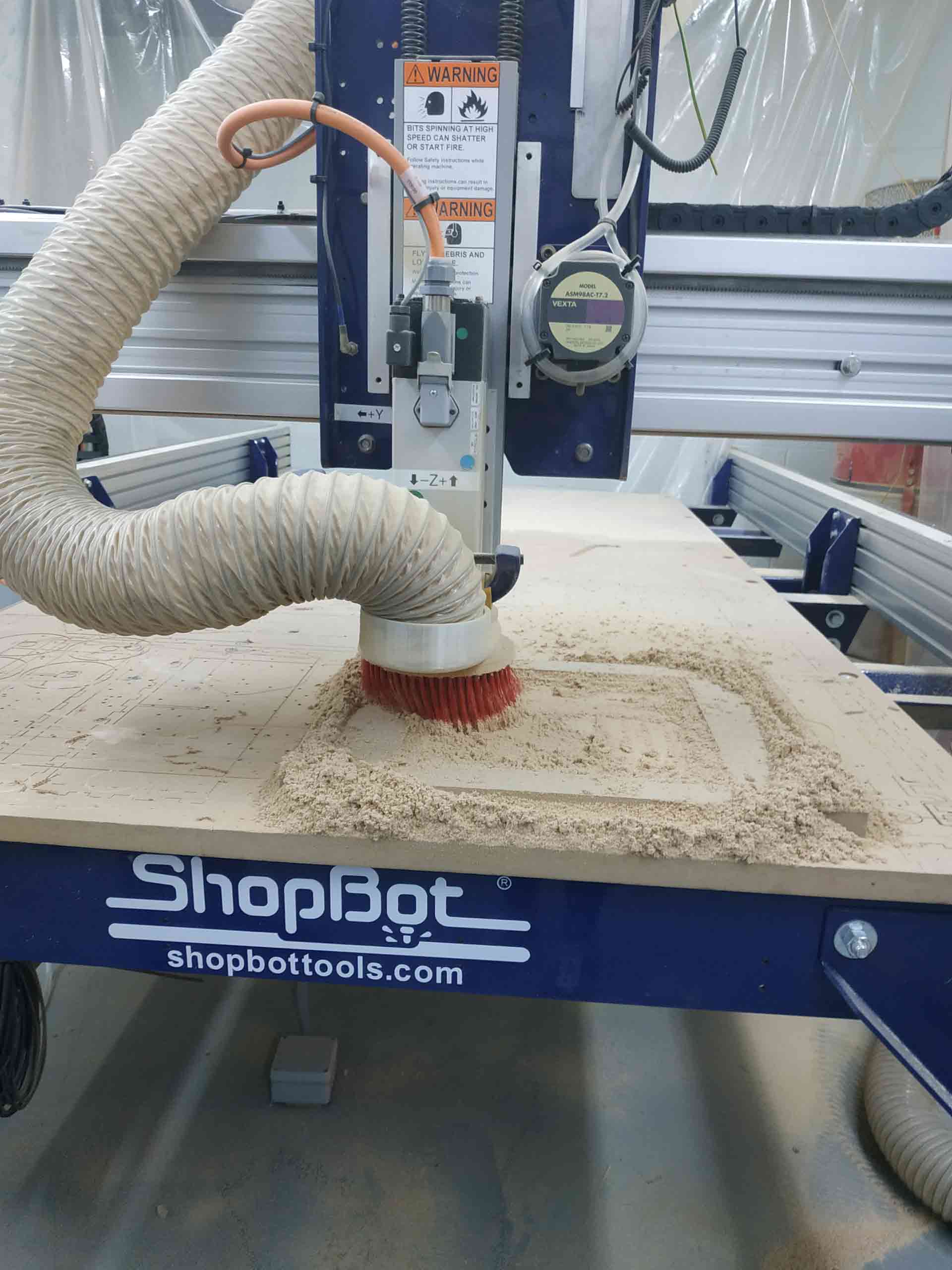
Computer-controlled machining processes
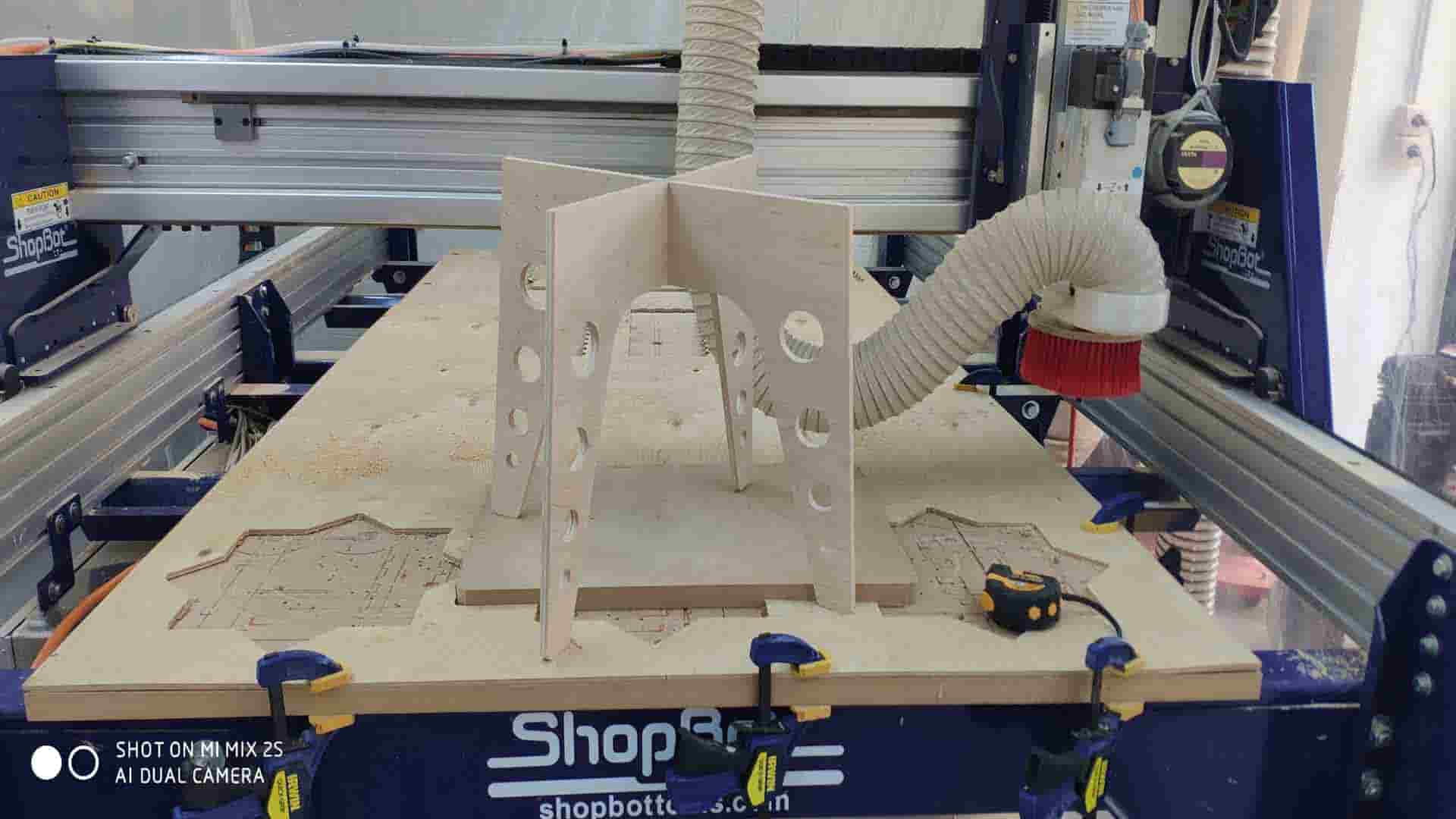
On Computer-controlled machining processes I need to cut the legs and surface of the desk using ShopBot. I have created 2 3D models one for Surface and one for legs using Fusion 360 and Audodesk Inventor Pro. I generated g code for ShopBot using Fusion manufacturing tools. For legs, I cut plywood 10mm thick using 1/8 inch tool(LMT ONSRUD 57-240 1/8”). For Surface cutting I used MDF 25mm think using 1/4 inch tool(ONSRUD 57-910 1/4“).

When MDF or other wood sheet is cut, a large number of dust particles are released into the air. It's important a respirator is worn and that the material is cut in a controlled and ventilated environment. It's good practice to seal exposed edges to limit emissions from binders contained in this material. So I turned on vacuum cleaner when I started to cut MDF.
When I cuted plywood (which is soft wood) I have given this parametrs for 1/8 inch end mill
And for MDF I have given this parametrs(for 1/4 inch end mill)
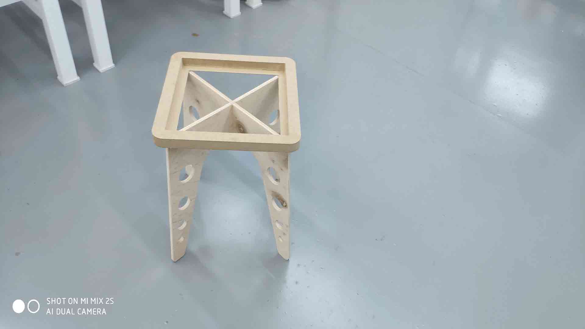
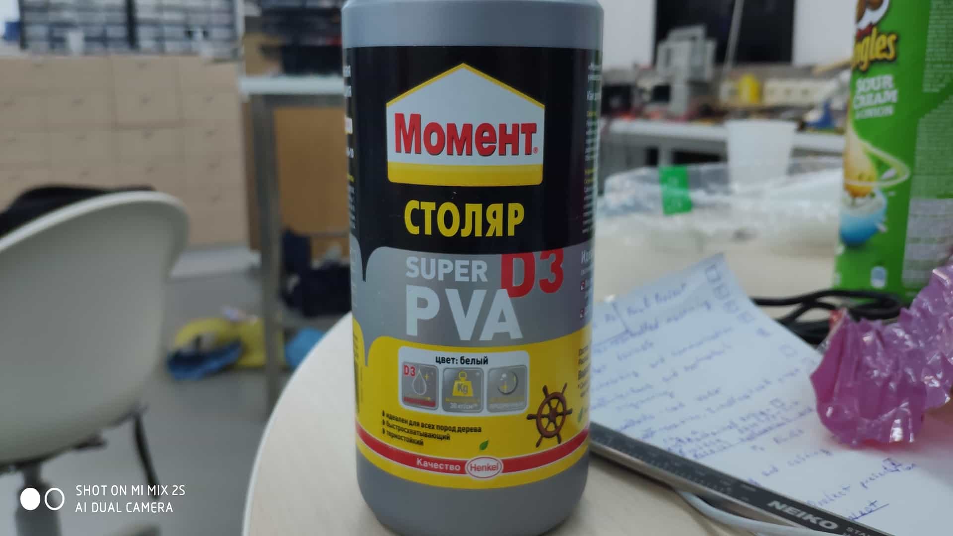
After successfully cutting all parts, I snap legs together and it was quite good (dog bonnes worked). I glue Srface and legs using Super D3 PVA glue for wood (30kg/cm^2) and leave for 40 min to dry.
Final Assembly is to try to fit 3D surface into the desk, and it was very successful, it fits perfectly.