Output devices
week 12
April 03, 2019
This week, we need to add an output device to our microcontrollers to do something. I decided to connect a stepper motor that will potentially end up in my peristaltic pump of my project after all.
Control a stepper motor
Find a stepper motor
The two popular types of motor for making a peristaltic pump are DC motors and stepper motors.DC motors are motors that run normally fast and to be able to vary their speed, the voltage must be limited by varying it. By reducing the voltage, you also reduce the power of the motor. This is not ideal in our case. We can also reduce the speed with a gear system but again I don't know exactly what speed I need to have a reasonable flow for the water.
For the stepper motor, it is easier to vary the speed because it is only necessary to vary the time between the steps of the motor. The advantage of this is that the motor does not lose force depending on the speed. So I chose to use this type of motor because I don't know the speed necessary to create my pump.
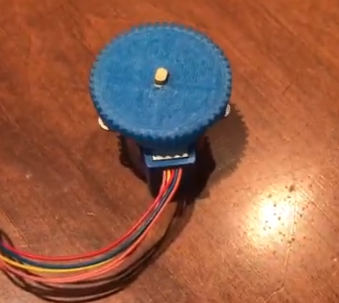
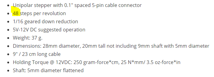
In stepper motors, there are several types divided into two main parts which are unipolar and bipolar. I already had a small engine and it is a unipolar. So I decided to design a baord to be able to control a small unipolar stepper motor.
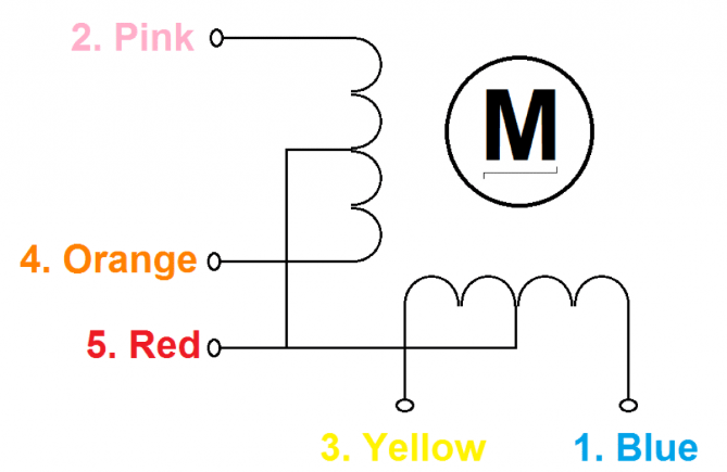
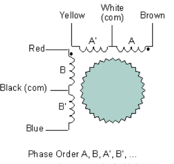
Here are two images showing the difference between a unipolar and bipolar motor. One of the main differences is the sequence of activation of the coils. Also in a unipolar there is a common wire to all the motor coils.

That is the configuration of the motor that I chose. Unipolar 5 wire.
*** Note: The next sections are identical to the corresponding sections of week 11. I did the same board so I could have the chance to interact with the inputs and outputs because it will allow me to test things for my final project. (Designed the board - Milling the board - Soldering the board) ***
Designed the board
To make a more integrated board, I decided to put all my inputs/outputs that I wanted to try on the same board so that I could improve it every week. This is the same board for input and output devices.Here's everything I want to put on this board.
- A button if a want to make some debugging
- A LED if a want to make some debugging
- Power LED to indicate if the board is powered
- Reset button if I want to reset the board
- ISP for programming
- FTDI for serial communication
- Themperature sensor (input)
- Light sensor (input)
- Distance sensor (input)
- Water level (input)
- Drive for a stepper motor(output)
I didn't look at how all the sensors work but only the pinout to be able to have the connectors on my board.
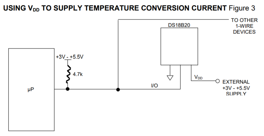
Temparature sensor
DS18B20 DataSheet

We only need a digital pin, a 5V power supply and a GND. We also need a 4,7k ohm pullup resistor as in the datasheet.
 Light sensor
TEMT6000 DataSheet
We only need one analog pin, one 5V power supply and one GND.
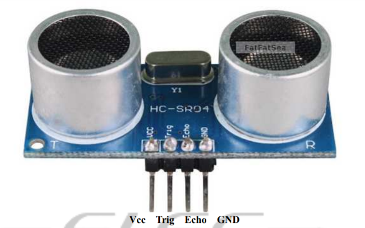
Distance sensor
HCSR04 DataSheet
Water Level sensor
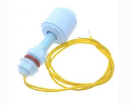
We only need a digital pin because the sensor works like a switch. This means that it sends a digital signal of 0 or 1 if the water drops below a certain threshold. A pin for the 5V power supply. Because the sensor is like a switch, we need a pullup resistor exactly like my switch a resitor of 4,7k ohm is perfect to limit the current.
Stepper motor

We need 4 connections that can make PWM and one connection to a 12V power supply. The system I have chosen to be able to change my signal from 5V to 12V is by means of transistors. I based myself on the following schematic found online.
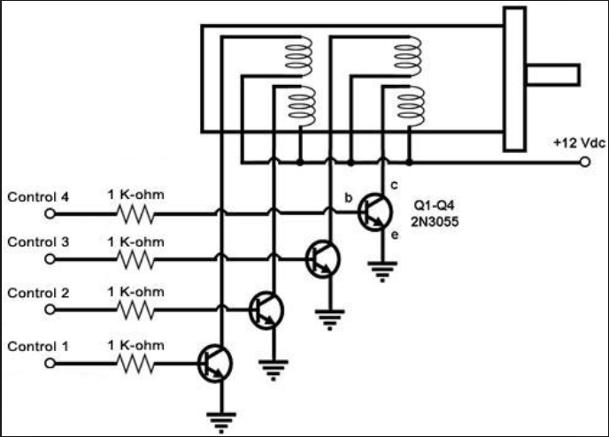
link to image
It is never good to leave a circuit open so I decided to put a pullup resistor on each transistor. I just need to put a small resistance to create this pullup because the current comes directly from the source so I don't limit the current with this resistor.
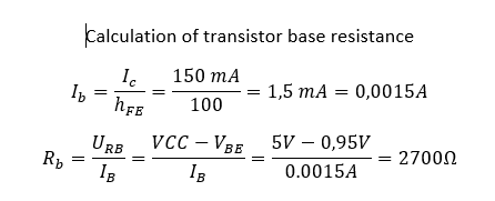
To calculate the resistor of the base transistor, I relied on this calculation. link
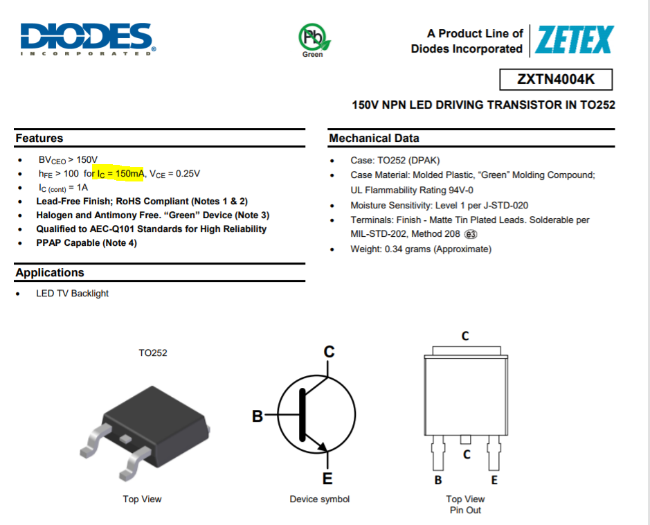
Here the datasheet of the transistor I chose.link
Here are the important data found in the datasheet.
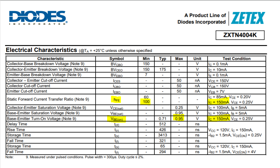
Here the calculation for transistor.
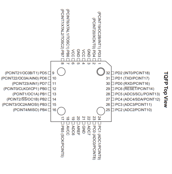
Now that I have the list of sensors to put on my board, I have to choose on which pin of the microcontroller to connect them.Because I have a lot of sensors, I decided to use the atmega328p microcontrollers because it has more connection and internal memory.
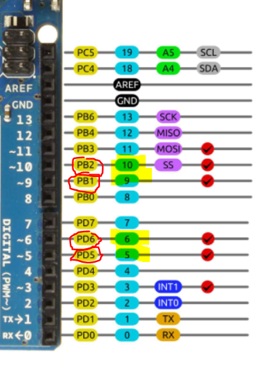
Here is the pinout of the microcontrollers
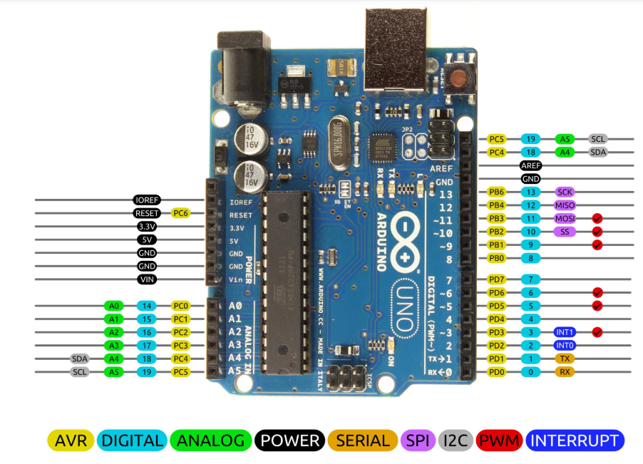
Another image that has helped me a lot with design and programming is this one. You can see all the different types of pin and also the corresponding number for programming in light blue.
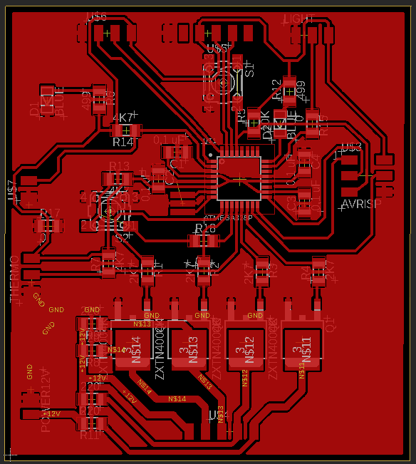
Here is the schematic, it should be noted that there are 4 decoupling capacitors on this board.
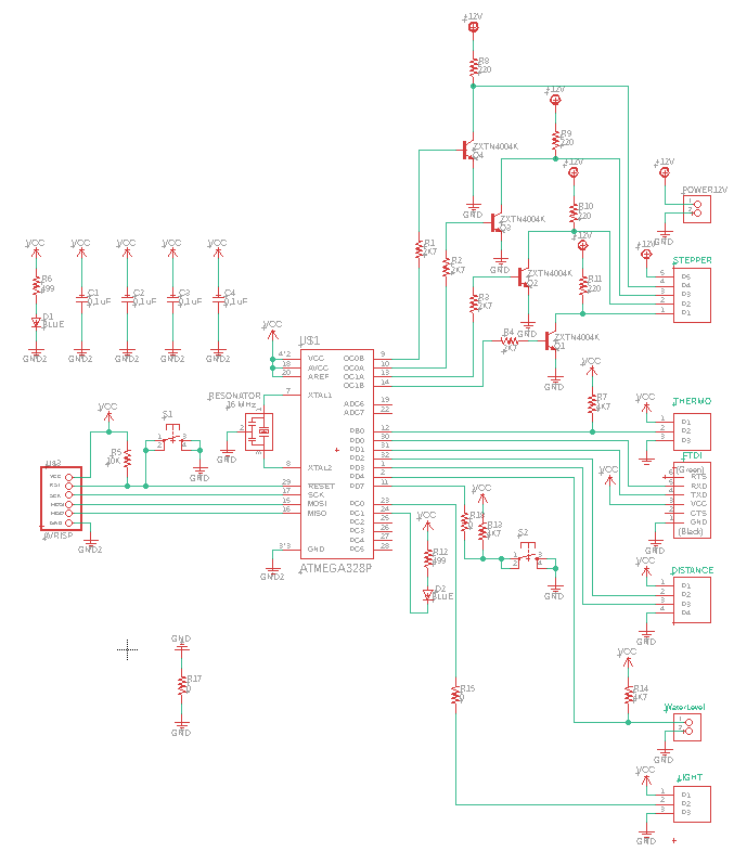
For the board, I placed the decoupling capacitors and the resonator closest to the microcontrollers to avoid loss problems. I then decided to put my traces at 15 mil because we could see the milling difficulties below that. The tracks for the 12V power supply are larger because a larger current will flow. It is always better to have bigger trace as possible to avoid problems.
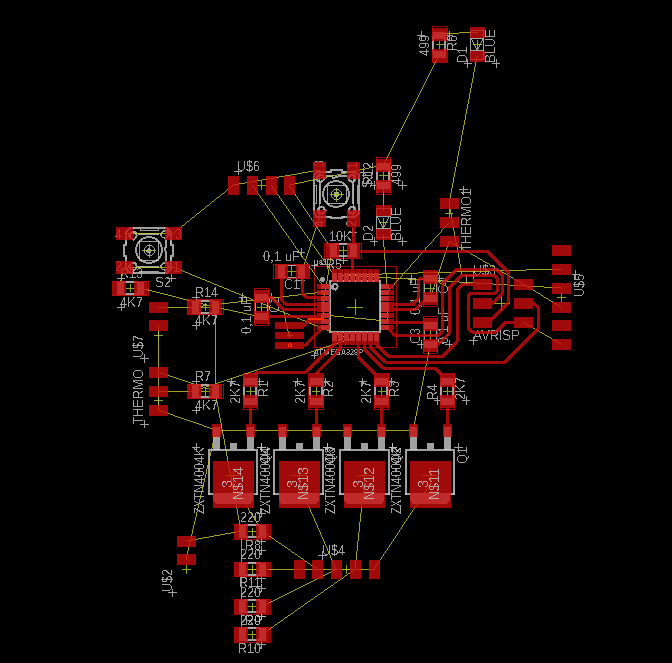
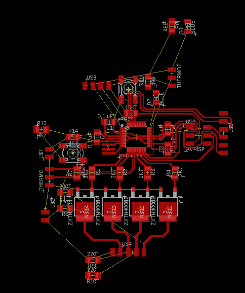
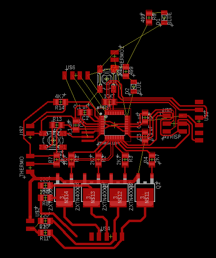
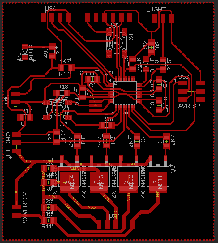
Here is the final result with the ratsnest.
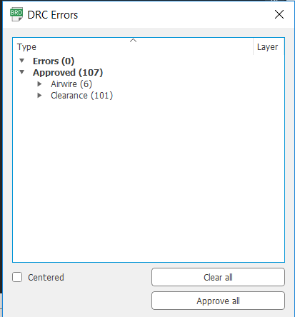
In the DRC, I put a minimum space of 15 mils between all. No error in the board except the airwires that are caused by jumpers and the 101 clearence which is the distance between the pins of the atmega328p that I can't change.
Milling the board
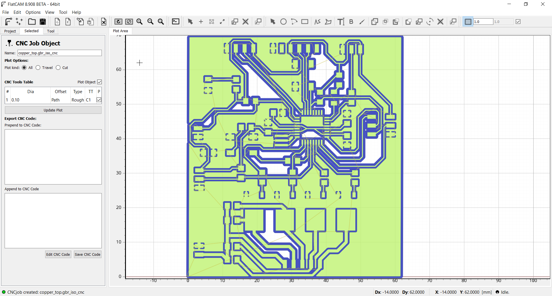
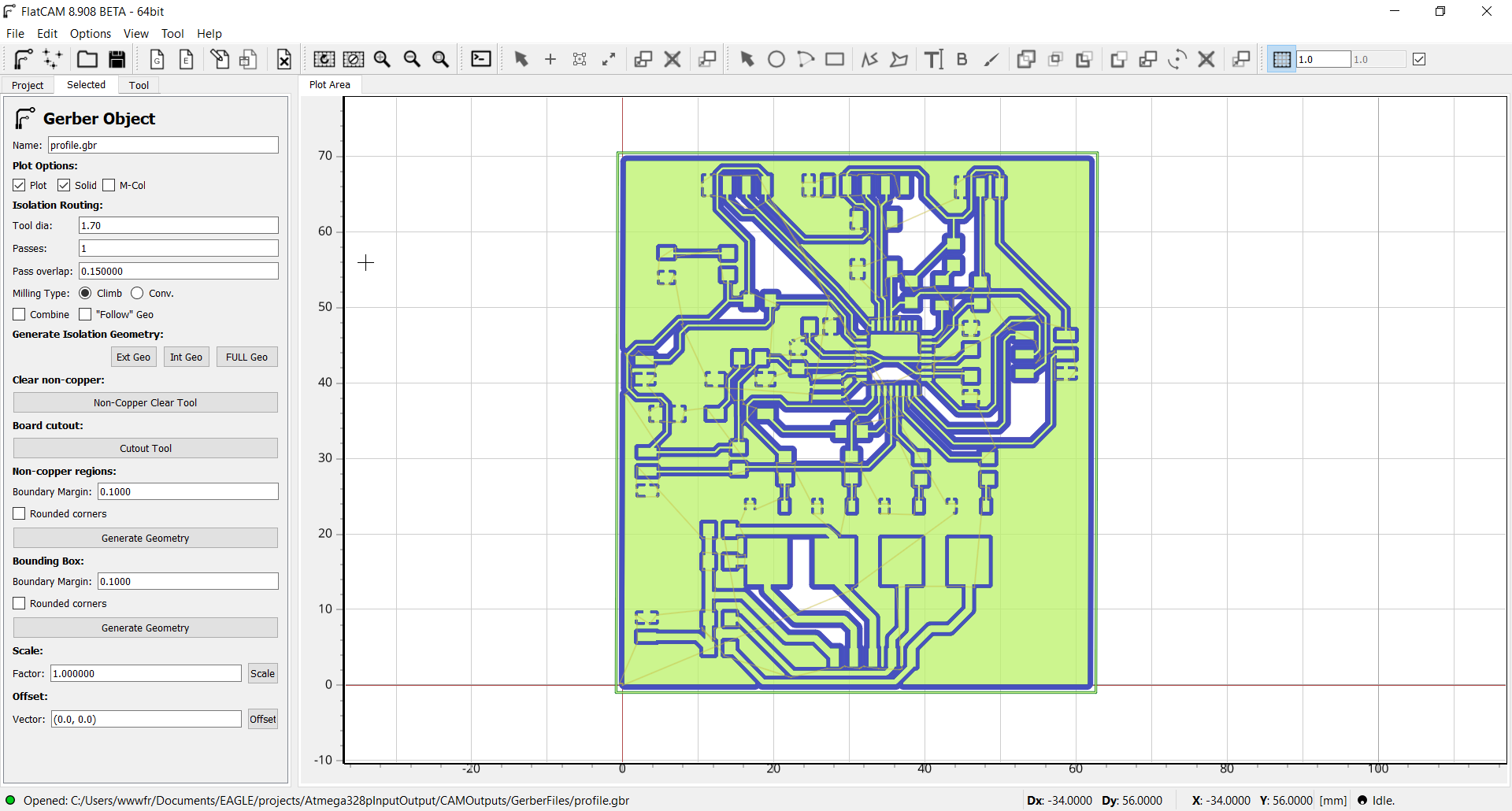
To start, I imported my board file into flatcam to be able to generate Gcode files for the CNC. The first job is the top of our board. It is necessary to make a full geometry and enter the following parameters.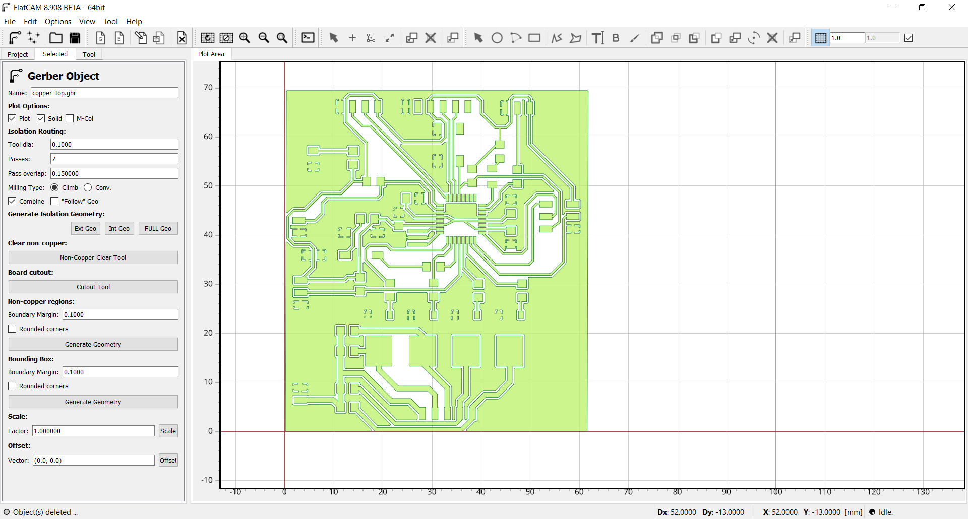
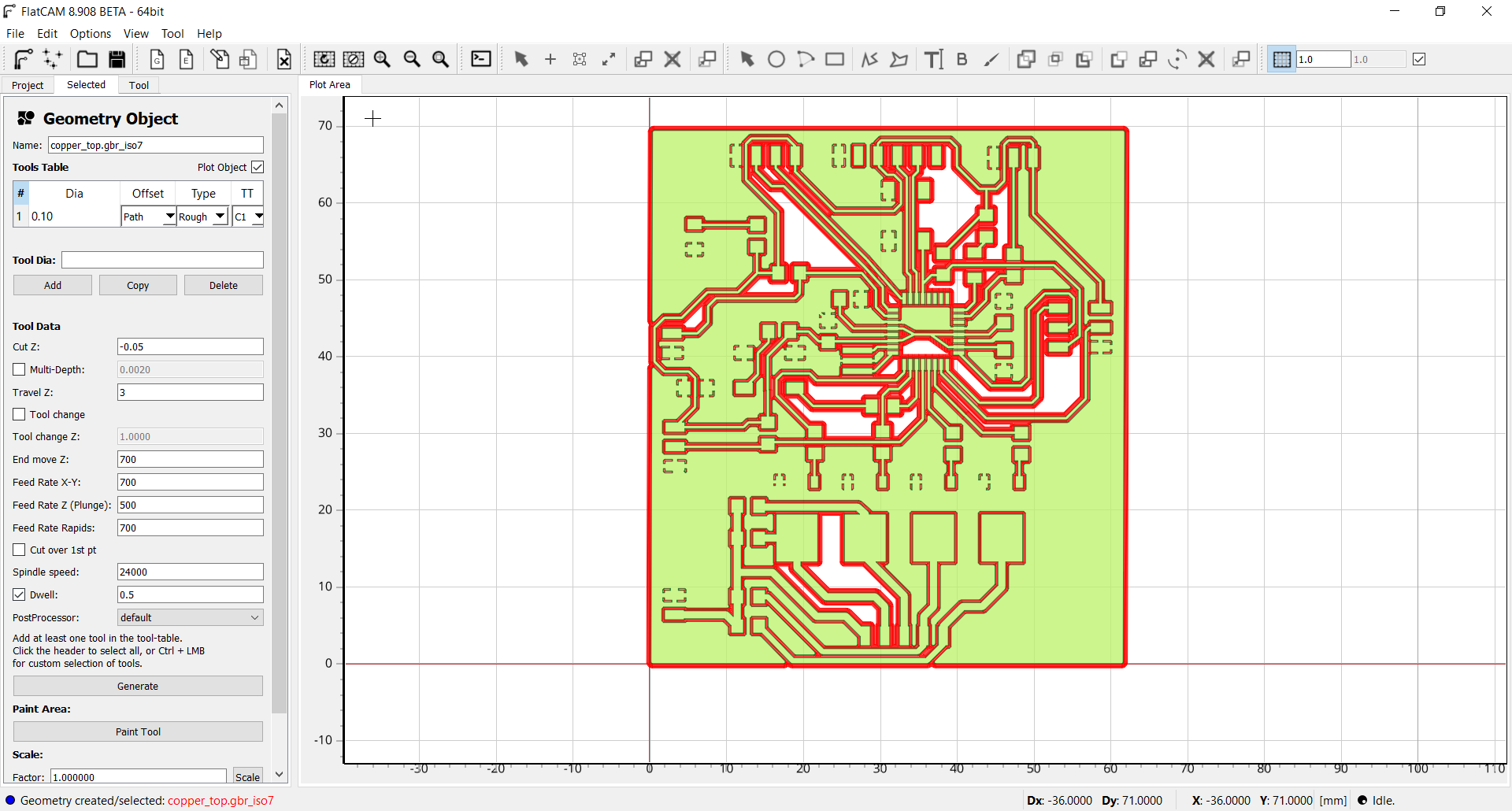
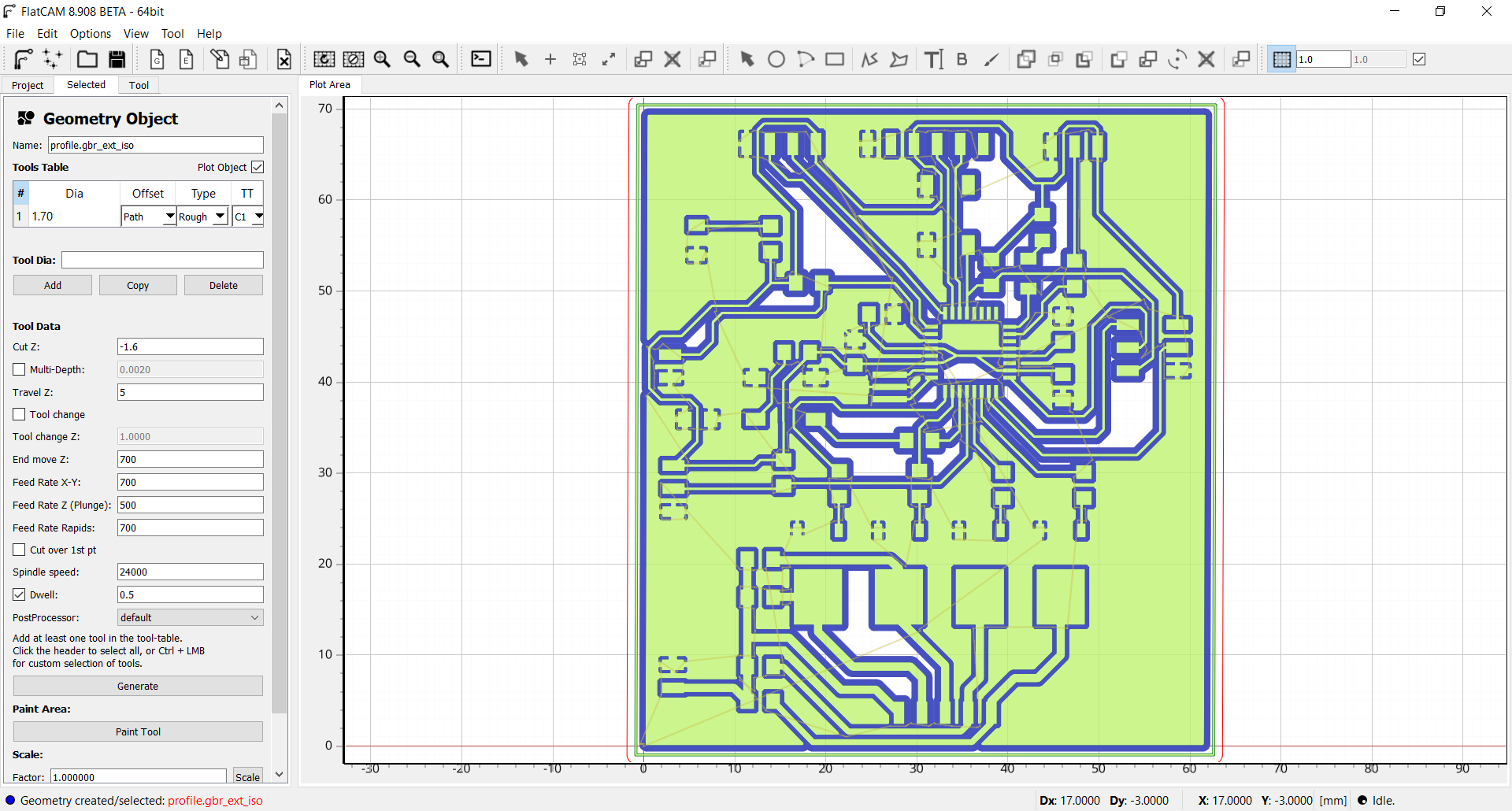
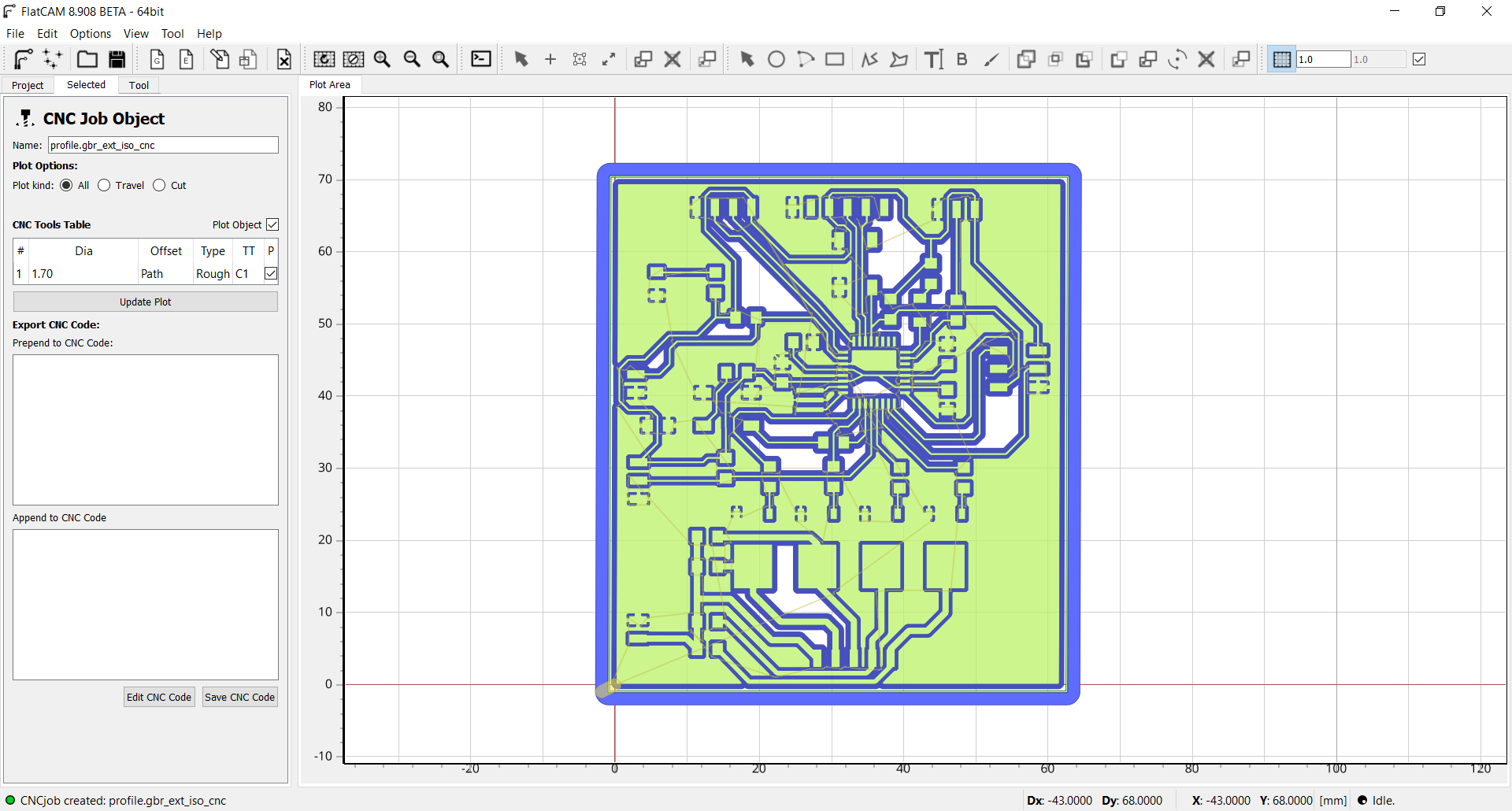
Now to make the board profile, it is important to choose extern geometry.
 The best way to make an origin is to do a conductivity test with a multimeter. Simply place a probe on the board and a probe on the tool. Go down from 0.01mm in Z steps to conductivity.

When the tool is positioned, it is necessary to indicate the 0 to the CNC by pressing the two buttons at the top left of the remote control.

Here the board during the milling.


Soldering the board
A good advice when soldering is to always start with the most difficult component. In this case it is the Atmega328p microcontroller. If we ever miss and damage the PCB, we will not have wasted a lot of time soldering the other components. It is important to align all the pins of the microcontroller before doing the first soldering. The liquid flux can help to keep it in place because it is a little sticky.

For the rest of the components it was easier because they were the larger components. The only one that is a little difficult is the resonator because the traces are not much larger than the component and it must be soldered on each side.


Here is the final result.

Program the board
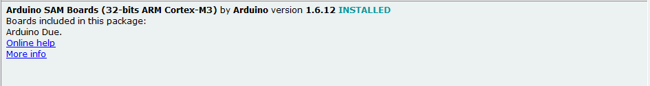
To make my program, I used the Arduino IDE. To be able to program the Atmega328p I have downloaded the corresponding board manager. To see more details on the installation you can refer to my week 9:Here is the link for the board file: atmegaga328p.
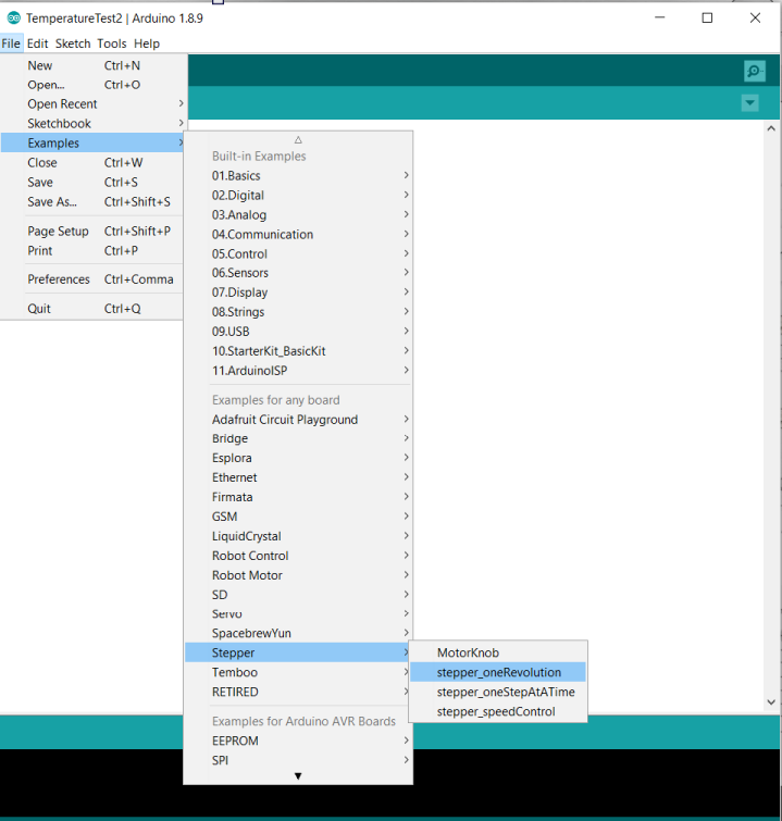
I saw in the examples of the Arduino IDE that there was a stepper section. So I started my program from this example.
To know on which pin of the microcontroler I had connected the motor, I used my schematic. The motor is connected to the 9,10,13,14 pins.
Now I have to look in the datasheet to see which port the pin number corresponds to. It's correspond to PD5, PD6, PB1, PB2.
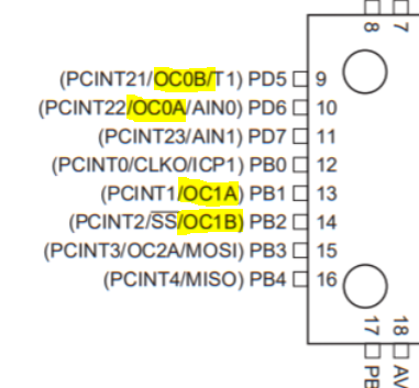
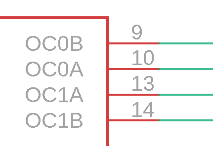
And finally, I looked at the ports to see which pin number in the program matched. They correspond to 5,6,9,10.
So I was able to enter the right pin numbers into the program.

Problem!!!! the engine doesn't run and only makes it vibrate. I did a little research and I have the image below. The motor vibration is caused by a wrong step sequence. Without relying on the color of the threads, we can see that the odre is not A, A',B,B' but A,B,A',B' so I changed the sequence in the program.

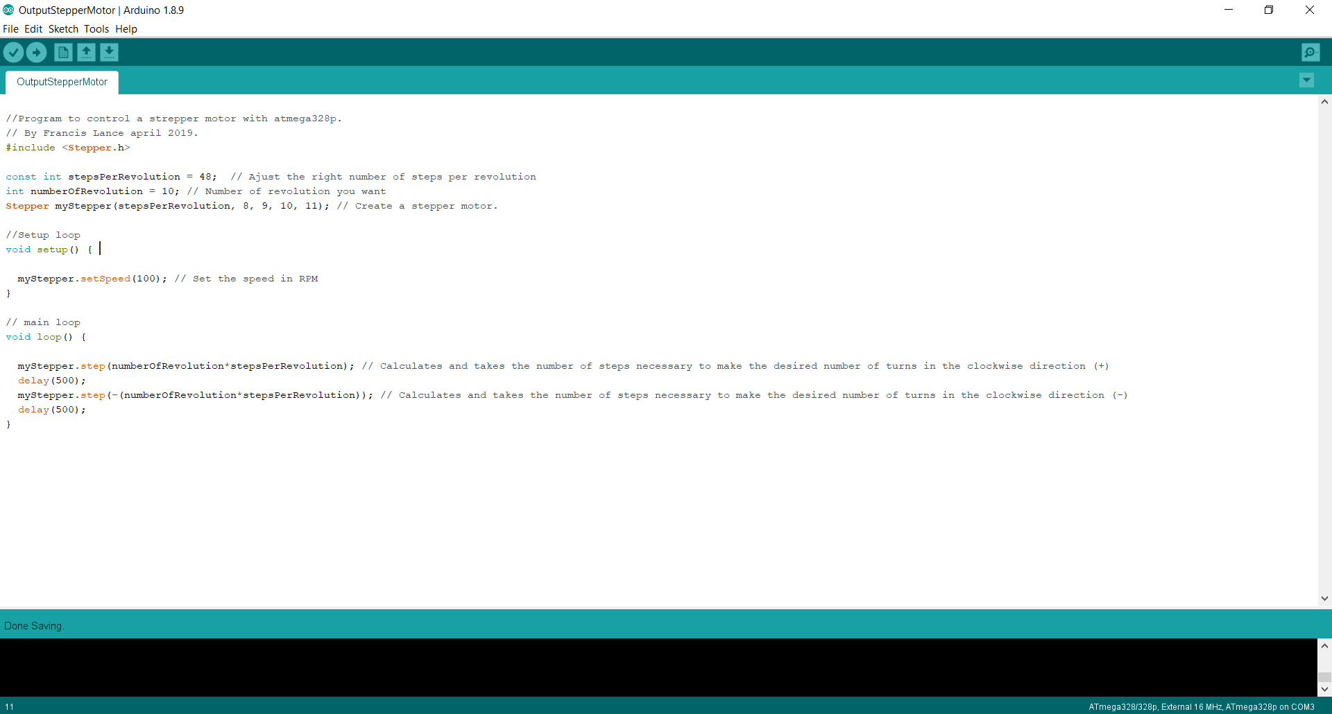
Here the program for the stepper motor. All the comments are in the program.
Here the number of steps per revolution for my motor that I include in the program.
Result
Here the video of the result.Group asignement
The person who documents the group assignment this week is Bomi.
You can download all the files of this week right here.