Networking and communications

week 14
April 24, 2019
This week, we need to design, build, and connect wired or wireless node(s) with network or bus addresses. I decided to get my board from week 11 back so I could be my master in communication and I need to build my slave board. I also decided to use serial communication to transmit information between my two boards. I decided this because I have a potential idea in my final project to transmit several parameters and I found that the serial was better adapted than the I2C.
Communicate with two boards using serial communication
Design the board
To do the slave board, I decided to use an attiny44 as microcontrollers because the program is very small and I don't need much I/O. I decided to make a versatile board so all the unused pins from the board I brought them to a connector. That way, if I want to connect something I can. For the design I took over most of the design from week 9. Here's the schematic.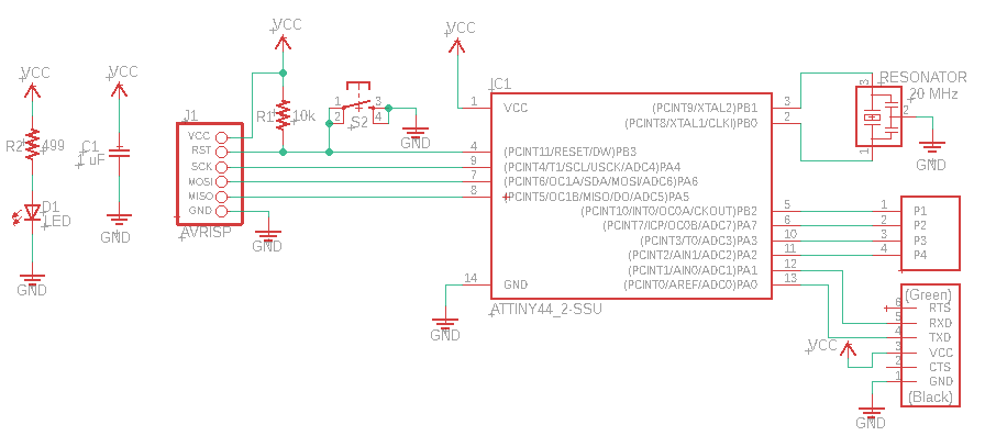
I wanted to make a very small board so I placed the components very close together. It should not be forgotten that the decoupling capacitor and crystal must be as close as possible to the micro-controllers to avoid malfunction.
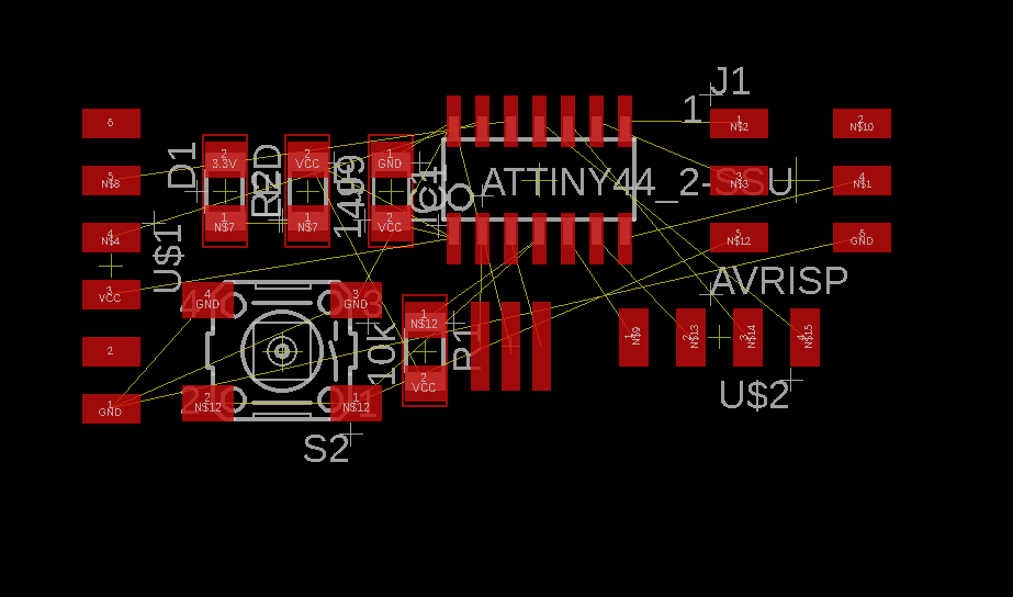
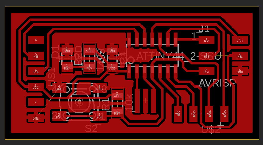
I routed all the components together and applied the ratsnest to the board to remove the least amount of copper during milling and also to have a ground plate.
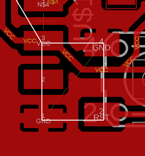
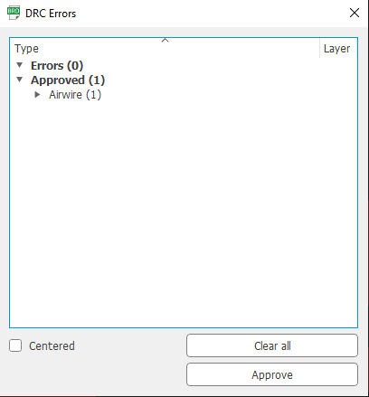
Now it is time to check for errors with the DRC. I set a minimum space of 15 mils between the components and the traces as a parameter. You can see that there are 4 things to check in the design.
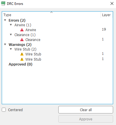
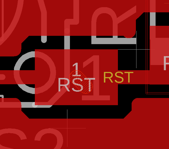
Here is the first problem which is the airwire. It is caused by the switch because eagle does not understand that the two connectors on each side of the switch are connected inside and do not need to be connected to the pcb. We can approve this error.
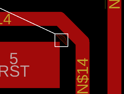
The other mistake is a lack of clearance caused by two traces too close together. The solution is to simply space them out.
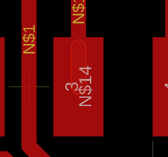
The next two are wire stub and it's caused by two traces one on top of the other. Simply delete the trace.
There is now no longer any error except the one that was approved.
Milling the board
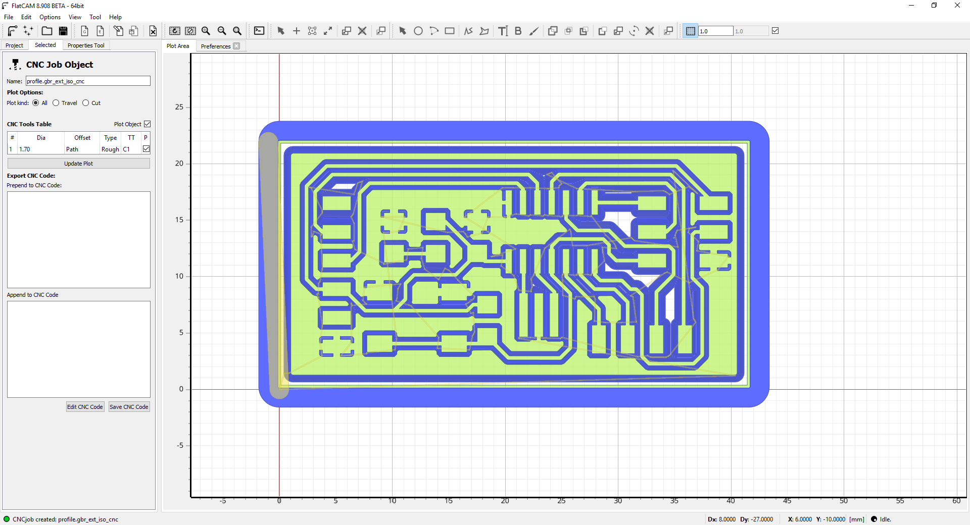
Now, let's prepare the CAM file by exporting our board.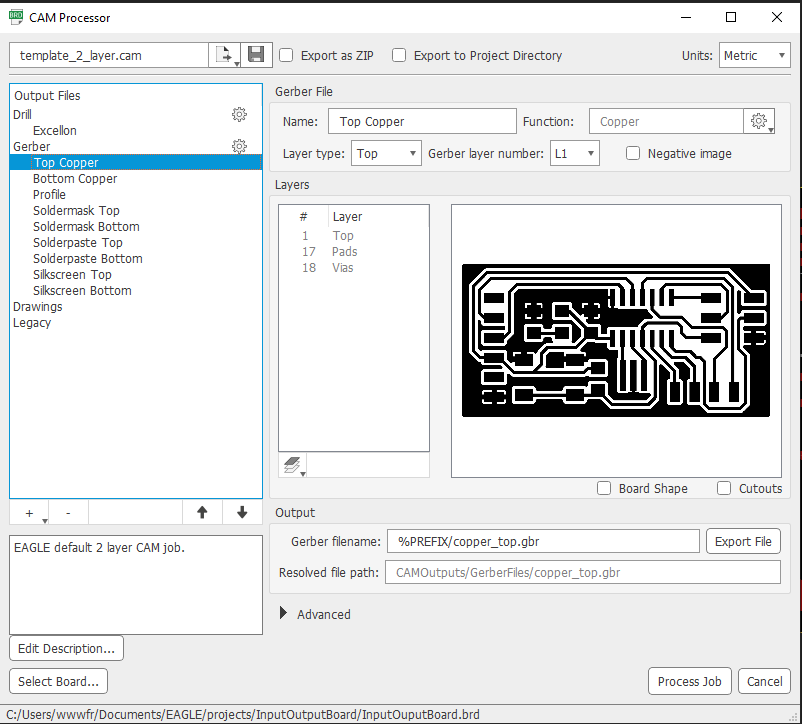
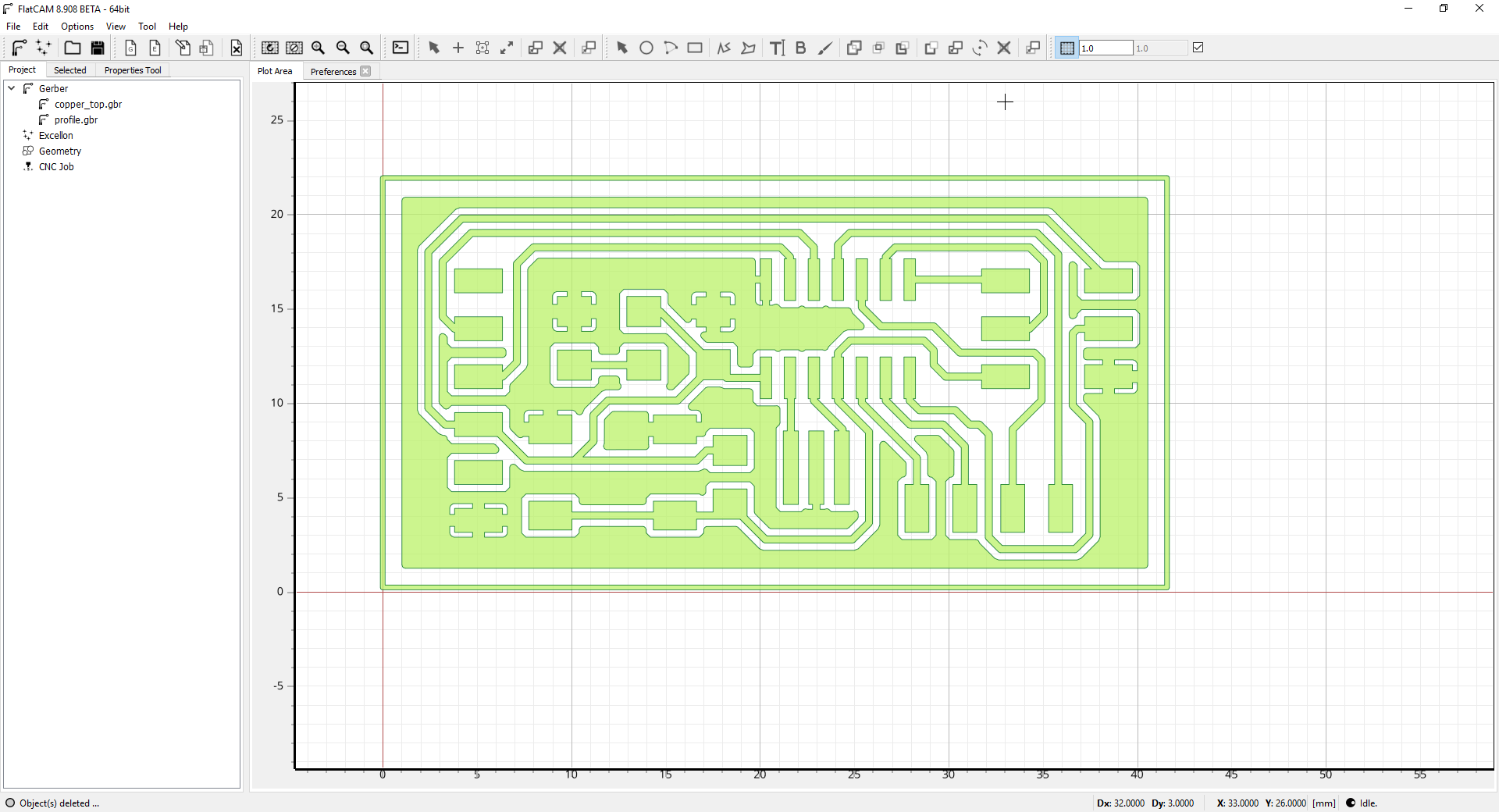
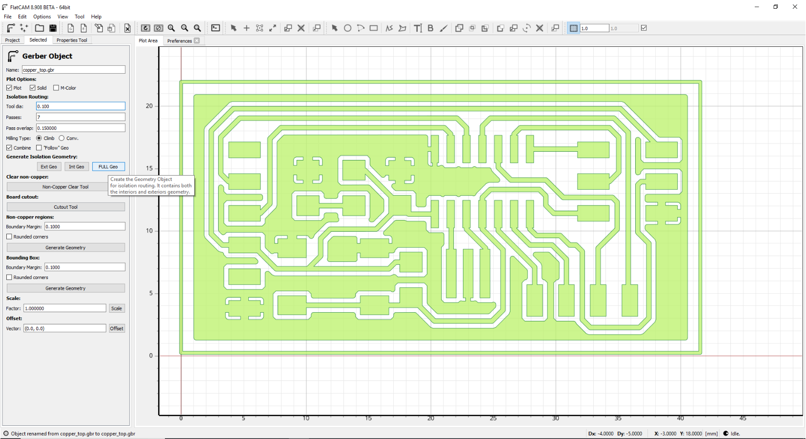
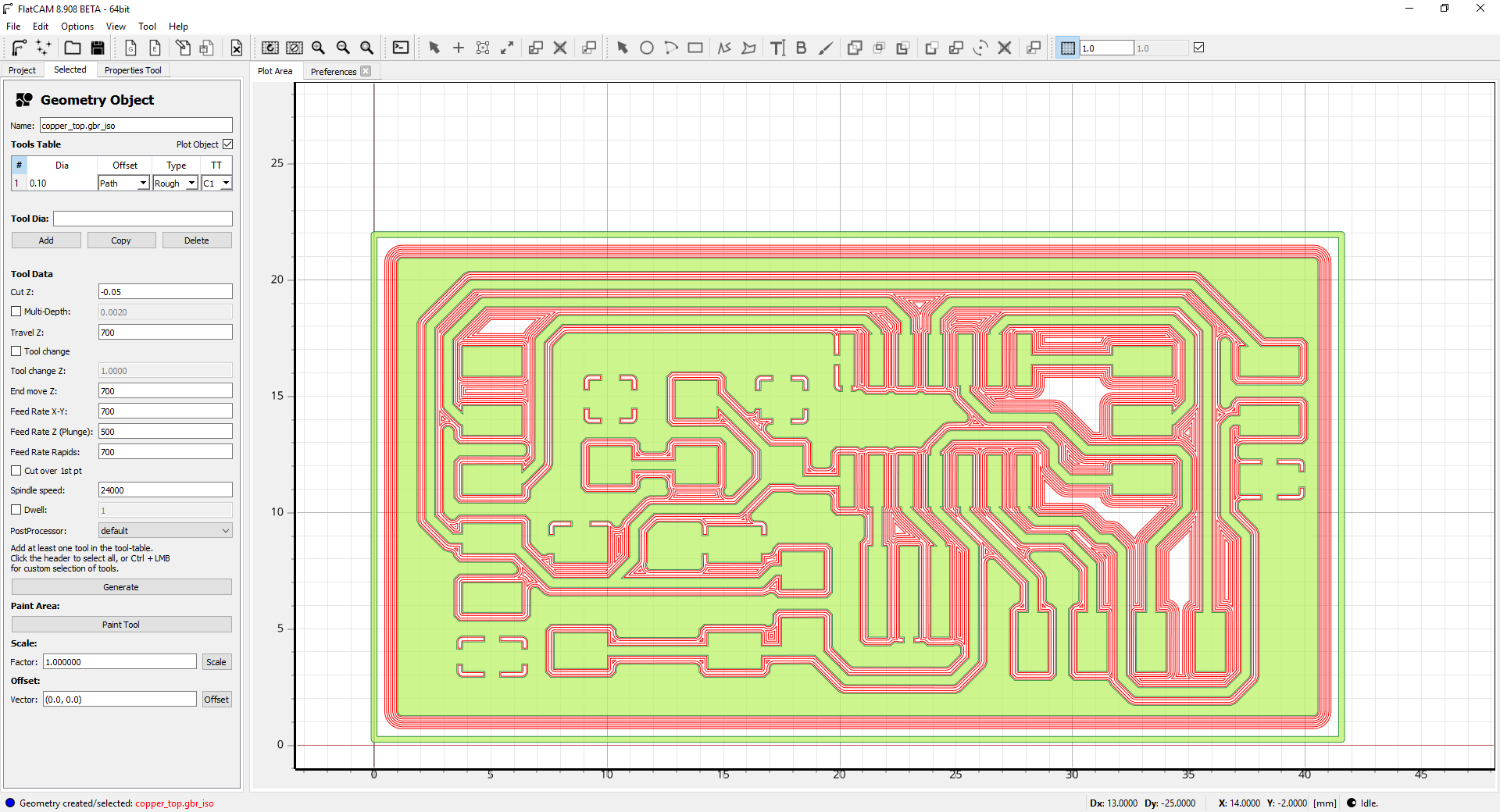
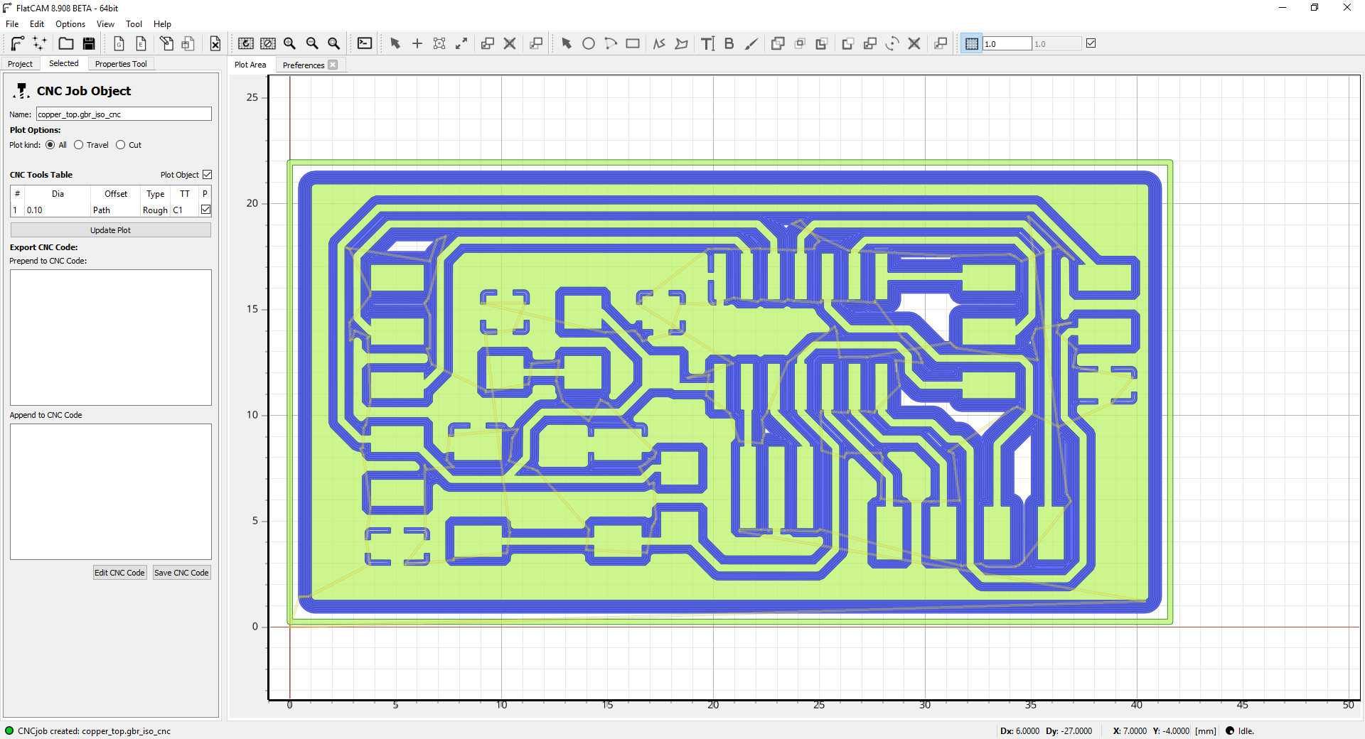
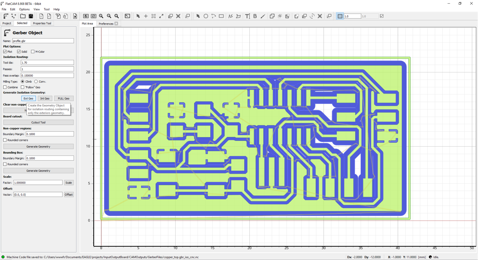
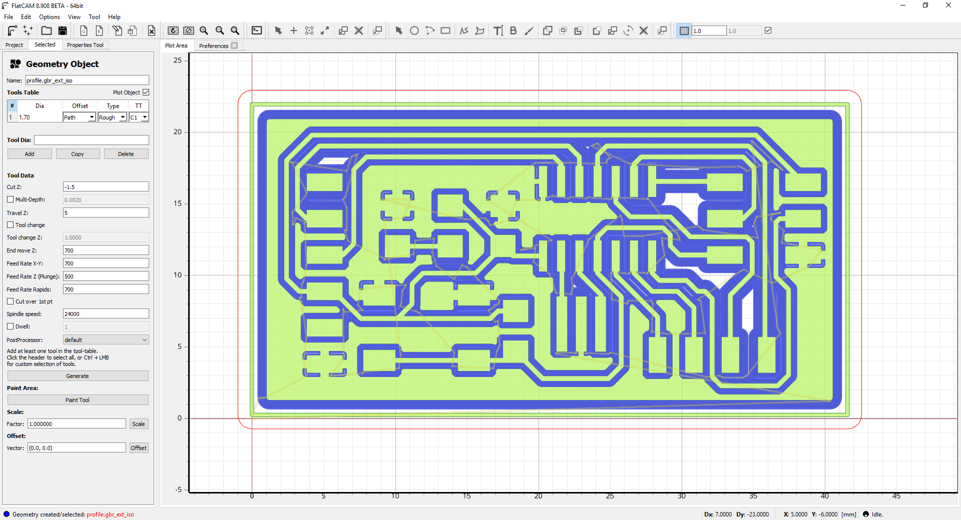
Import the gerber file into the FlatCam software to generate the GCode for the milling machine. It is only necessary to enter the following correct parameters for the SMX 2x3 foot milling machine.
Now that we have the GCode file, it is important to make the origin with the two buttons on the top right of the remote control.

The first attempt was unsuccessful because the tools were too hollow. I noticed that the CNC plate is not perfectly straight so I moved my plate to make another try.

Here is the final result of the milling process.

Soldering the board
As I have already said, it is good to start with the most difficult component to solder because if you have to do it again it is less harmful. In our bus here, it's the attiny44.
Here is the attiny44 of view in a microscope that I use to make soldering.

A good product I discovered to clean the board after soldering is the flux remover in spray.

Here is the final result.

Program the boards for serial communication
Program the slave boardTo establish a serial communication, I decided to take the board with the attiny44 to be the receiver of the communication. The reason is that in my potential final project, I want to communicate with a drive and send it the speed of rotation of the motor. For that I started by making a program to send a number to the serial port using a terminal on the computer and make an echo of a number and not the characters of the number. When writing a program that communicates with others, it is important to be able to test each part independently to limit errors. Otherwise, if we test everything together, it is difficult to identify the problem.
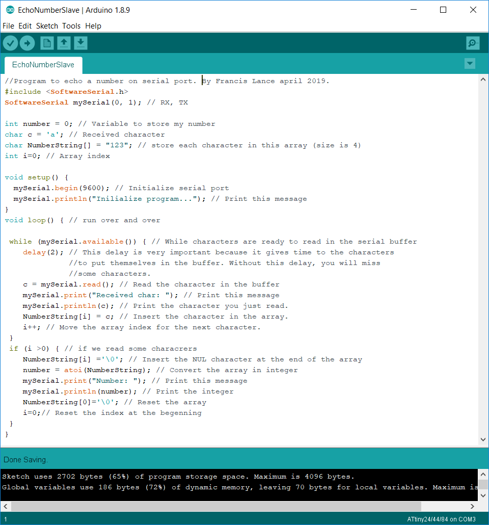
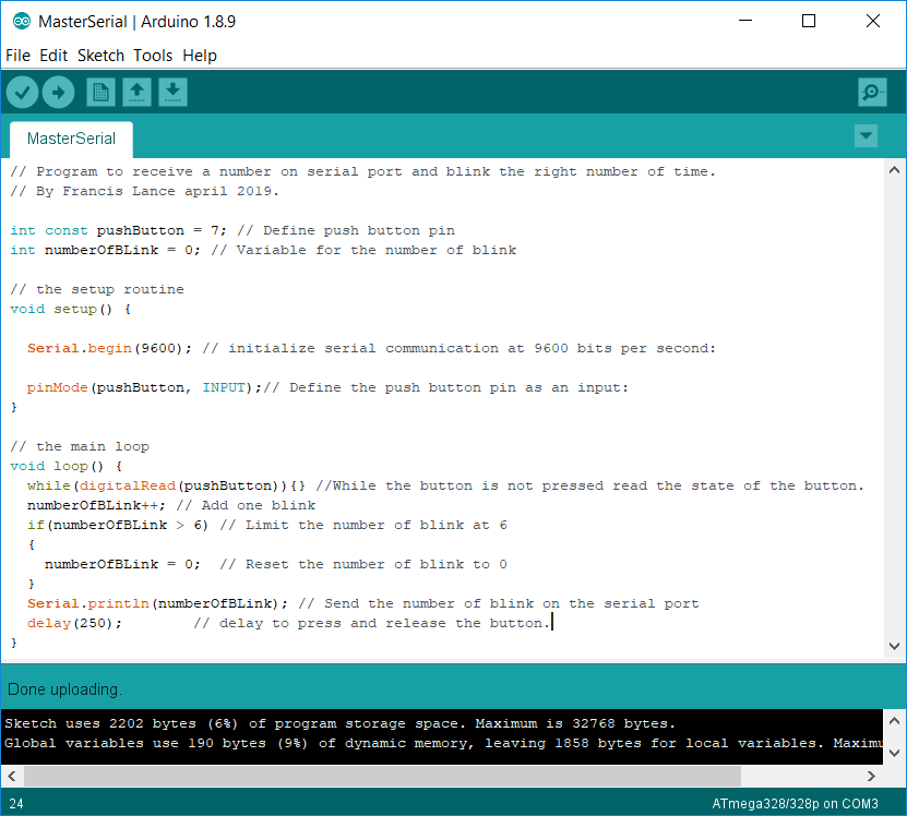
This is the first part of my communication program which is to do an echo on the serial port.
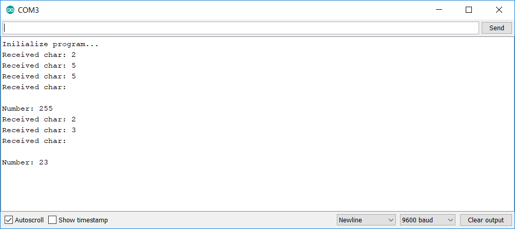
You can notice that when I send a number from the terminal, the program makes an echo of each character and then when all the characters are received, it sends the number.
Here is the program. All the comments are in the program.
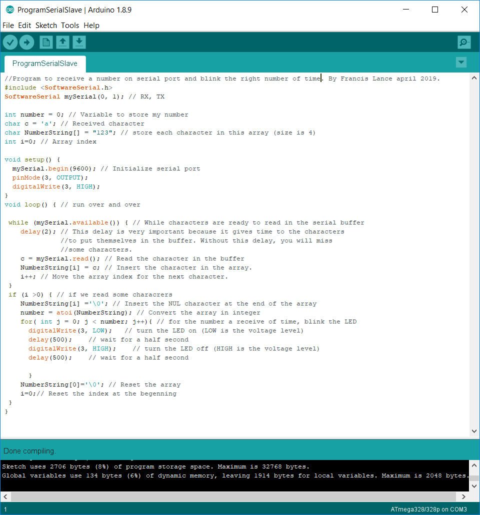
The next step is to make one del flash the same number of times as the number sent using the terminal. It is at this point that I noticed that I hadn't put LEDs on an output of my board. I moved it to the power supply to see when the board is powered. So I took an external del that I connected to an input of my board. The program is the same but instead of doing the echo it flashes an LED.
Here is the program. All the comments are in the program.
Here is the result in video.
Program the master board
Now that our slave board is running, it remains to make the master program that will send a number to the slave. To test with a different number, each time I press the master's switch, it increments the number of flashes by 1.
Here is the program. All the comments are in the program.
Both boards together
Here is the result in video.
Program the boards for serial node communication
Program the master boardNow that I am able to communicate between two boards, I will now create a communication with a node. This means that there will be a board master and one or more slaves listening on the same node. Now the messages must be addressed to a particular board. In the communication protocol, I only need to send information to specific boards. I really like spectable lights and they use the DMX protocol (RS-485). This protocol works with the same principle of 1 master sending data and several slaves listening. The way the protocol works to travel a long distance is for each slave to repeat the message to the next. It's a way to amplify the signal. I found this principle intelligent so I did the same principle but with the serial protocol.
First, I took over the previous master program so that it would send a message to slave 1 and a message to slave 2 alternately. For this reason I must combine in the message the slave ID and the number of blink in the same message. When I press the button, the data is sent to the serial port.
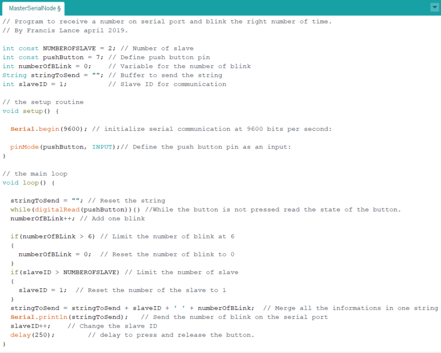
It is possible to see on the screen that the left digit of the space represents the slave ID and the right digit represents the number of flashes. Each line represents a different message.
Here is the result in video.
Program the slave board
For the slave, I took over the previous slave program which blink the LED the number of times it is sent to the serial port. However, in order to be connected to a communication node, the slave must now check whether the message is being sent to him. To find out, the slave must break the received message to separate the slave ID and the data.
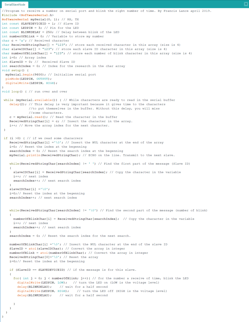
I send a serial message containing the slave ID followed by a space followed by the number of LED flashes. In this example, the slave ID is 1 so the LED will only blink when the ID is 1 and will let other messages that are not intended for it pass through. Here is the result in video.
Both boards together
Here is a diagram of the final connection.
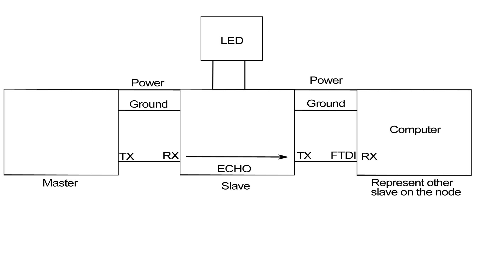
Here is the result in video. When I press the button the data is sent alternately to slave 1 and slave 2 which is not connected. The computer is represented by an undefined number of slaves who can listen on the node. We see that the slave repeats on the node to the next slave who is the computer.
Group asignement
The person who documents the group assignment this week is Philippe.
You can download all the files of this week right here.