Embedded programming
Assignments
#1 - Read a microcontroller data sheet. Program your board to do something, with as many different programming languages and programming environments as possible
To start, I will explain the major differences between microcontrollers, PIC and single-board computers. Then I will focus on the AVR family from Atmel and the tools that are avaialble to program them. The board I will be using will be the one manufactured during week 7.
References
Lecture
This week is about embedded programming but I did some extra work related to production as well:
- Please meet the AVR family
- The siblings...PIC
- Not in the same game: SBCs
- How to find and read a datasheet ?
- The challenge for this week
- How to use C language to program your AVR ?
- How to use Arduino IDE and libraries to program your AVR ?
Recitation
(D)esign is a vision of the future, a decision making process, an exploration of potential realities... while (d)esign is how to make it real today, using all the tools and techniques available.
Topics covered (course) Video recording (course) Video recording (recitation) Students and Labs My filesLearnings
EXTRA WORK - Surface mount production using a reflow oven
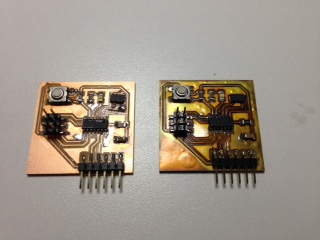
I completed the assembly of my DIY reflow oven and I used it with a first PCB. Two weeks ago, I had a issue with my PCB (the footing for the crystal was to small) and I had to create a new revision for this week. For the reflow ove, I followed this tutorial and here is how the final product looks like

The main advantage of this oven is that it follows the reflow temperature curve for the material used for soldering (lead or lead-free solder). Here is the one for the KESTER EP-256

The output looks surprising (I think the decoloration is related to the FR4 material) but it works perfectly. The board on the left is soldered manually and the one on the right comes out of the reflow oven
The AVR family
(from Wikipedia) AVR is a family of microcontrollers developed since 1996 by Atmel, acquired by Microchip Technology in 2016. These are modified Harvard architecture 8-bit RISC single-chip microcontrollers. AVR was one of the first microcontroller families to use on-chip flash memory for program storage, as opposed to one-time programmable ROM, EPROM, or EEPROM used by other microcontrollers at the time. AVR microcontrollers find many applications as embedded systems. They are especially common in hobbyist and educational embedded applications, popularized by their inclusion in many of the Arduino line of open hardware development boards.
I have been using the ATmega328 (the one installed on the Arduino Uno) for a while and I recently discovered the tinyAVR series with Fab Academy
To select an AVR, it depends on what you want to achieve and how much money you want to put on the table. For one prototype, any of them is definitely affordable (it varies from less than $1 to less than $20) but for mass production every cent count and there should ne no reason to overdesign. Here are some criteria to take into account (I know, my summary is oversimplified but I hope it helps) :
- Performance: the higher clock value you get, the faster you can run in term of executing lines of code. But .. the high clock value means also more current and .. more heat (it is critical on PC processors but not that much on MCUs)
- Storage: amount of flash determines how much code could resides on it, amount of SRAM limits how much short term volatile memory you can get and EEPROM is the long term permanent storage (for configurations for example). Note: there are ways to cheat and the limit betwen flash and SRAM is not that clearly separated
- Interfaces: depending on what you want to connect to your MCU, you may need just simple GPIOs (check how many you need ! ), I2C or SPI interfaces or UART or even on board USB
- On board HW processing agents: PWM is usefull when you want to control a servo or dim a LED, ADC is gateway between the analog and the digital world
- Packaging: could be as big as a through hole or as small as you cannot really solder it manually or even .. see it
- On board SW agents: you may need cryptography for example
You PIC(ed) my curiosity
Before Fab Academy, I had no clue what PICs were and how to compare them with AVRs. Both have links to MicroChip Technology company. I found this comparaison and the conclusion is ... it depends what you want to achieve and the criterias I listed for AVRs are still valid for PICs. But Arduino guys may have change the big picture, especially for hobbyists when they clearly simplified the "getting on board" process in the embedded development world with their products (along with their IDE). For mass proudction, PICs may be a better choice, depending on what features you need and how you are confortable with development environment (that looks older by the way..) .
This is not part of the PIC topic but there is another family I heard about: the MSP and especially the MSP-430. The MSP430 is a mixed-signal microcontroller family from Texas Instruments. Built around a 16-bit CPU, the MSP430 is designed for low cost and, specifically, low power consumption embedded applications. They try to get some traction with hobbyists. See this link for a list of projects based on the MSP-430.
Single Board Computer (SBC)
(from Wikipedia) A single-board computer (SBC) is a complete computer built on a single circuit board, with microprocessor(s), memory, input/output (I/O) and other features required of a functional computer. Single-board computers were made as demonstration or development systems, for educational systems, or for use as embedded computer controllers. Many types of home computers or portable computers integrate all their functions onto a single printed circuit board.Unlike a desktop personal computer, single board computers often do not rely on expansion slots for peripheral functions or expansion. Single board computers have been built using a wide range of microprocessors. Simple designs, such as those built by computer hobbyists, often use static RAM and low-cost 8- or 16-bit processors. Other types, such as blade servers, would perform similar to a server computer, only in a more compact format.
At EXFO (my day job), I'm using SBCs every day and most of our products are designed from customized SBCs. We are also using AVRs for peripheral controls and dedicated tasks (like energy management)
To illustrate what SBCs are vs AVRs, let's assume you want a blinking LED on your product. You could build a HW circuit (around a 555 timer for example) and that circuit would be perfectly reliable (since it has nothing else to do). You could use a GPIO port on a AVR and the advantage would be the fact that you can upload new SW in the chip if you want to change the blink rate for example. You could (but you should not..) rely on a SBC. But then you depend on multiple layers (driver, operating system, thread priorities, ..) and the probability to have a stable blinking frequency is quite low.
In the hobbyist world, Raspberry PI, BeagleBone and the SnapDragons are well known examples of SBCs. Note that both of them are ARM based architectures (like your phone but unlike you laptop .. unless you are a Chromebook fan).
What is a datasheet and where to find it ?
A datasheet contains everything you want to know (and even things you thing you will never need to know.. ) about a HW part. I found the ATTiny44 datasheet on Microchip web site and I extracted some parts that will be useful for the challenge I will explain in the next section
I read tutorials from Sparkfun as well. There are tons of informaton there on how to hookup Atmel MCUs and to program them. Most of the information in the following lines come either from this site or from the datasheet
The challenge
Here is what I want to achieve:
- At startup, LED is Off and the MCU is waiting for commands from the terminal
- When a "S" (start) command is sent, the MCU will turn the LED On
- When user press on the button, the MCU will turn the LED off and send a message (user acknowledge) to the terminal.
The LED is connected to port number 5 and to the GND through a resistor. To turn the LED On, the MCU has to set the port number 5 to HIGH
The button is connected to port number 6 and there is an HW pull-up to force it to HIGH unless someone push on the button (then it goes to LOW until the button is depressed)
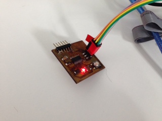
I already have a working board (from week 7) and I know the FTDI communication works. I will start from there and add the missing use cases:
Using the C langage
Two weeks ago, I programmed my board and the detailed procedure is here. The idea was to demonstrate the communication between the MCU and a terminal running on a PC
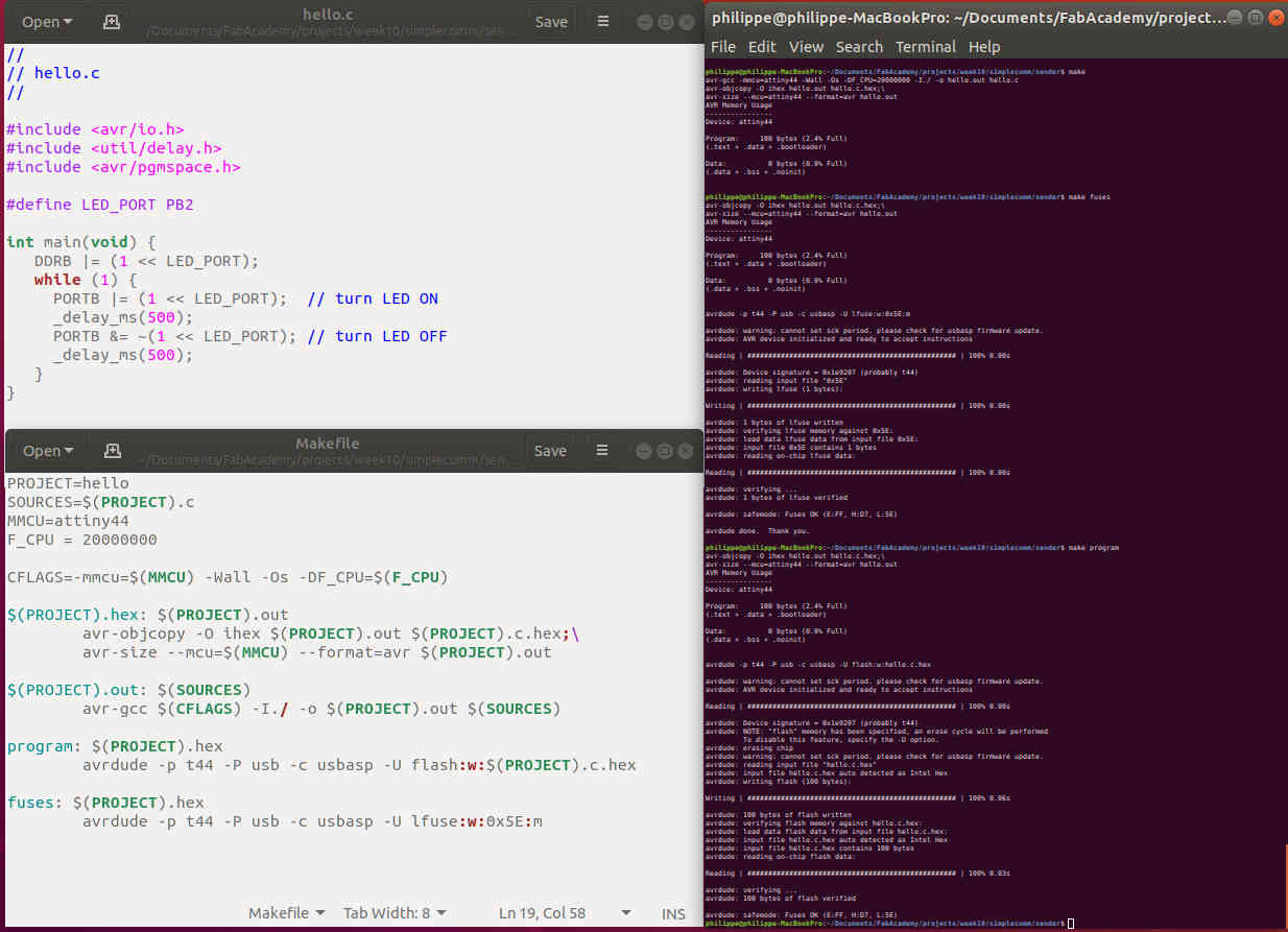
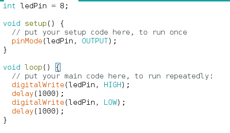
This week, I don't want to spend much more time on pure C (i.e outside of the Arduino environment) programming. But I have to demonstrate I can code someting in C langage and here it is. This is a very simple piece of code, along with the makefile, that makes the LED on my board .. blink
I think it could be usefull (based on questions I received...) for other students to document some concepts harder to understand. Here it is...
-
Macro in C langage. Nothing to do with Excel (or any other Sw) automated tasks some of you may know. The idea is the following. You write source code then the compiler (gcc) comes and it compiles it, ie. it transforms it into machine readable instructions. There is a step just before compilation where you can ask the pipeline to substitute some "text" with other "text". Here is an simple example
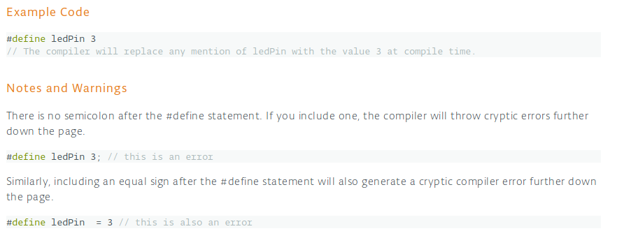
Note: there are more complex example where you may want to substitute an entire function along with the parameters. And one last thing you may ask: what is the advantage of a macro vs a constant to declare something like "the speed of the light" for example. Simple answer, defines do not take space in the memory at run time, constants (most of the time) do.
-
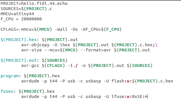
Makefile A makefile is kind of a receipt book that is used by the "make" utility. I found out this simple tutorial that will help to figure out. In our Labs, when we type "make fuses" it means, "Dear make utility, please search into the makefile an entry named fuses and execute whatever is listed under that tag. In the following makefile, it means executing the avrdude program with the parameters listed above.
-
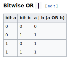
Bitwise operator in C langage. n the C programming language, operations can be performed on a bit level using bitwise operators. To start, let's make clear what the difference is between "bit" and "bytes". "bit" is the smallest representation of a reality in the computer world. It has only two possible values: 0 or 1. "byte" is a set of "bits", most of the time 8. "byte" is used to represent a reality more complex than a bit. By convention (ASCII standard), a "A" character for example is represented by 01000001 in binary representation. Modern computers manipulates set of bits (could be 8, 32 or even 64) at a time, not one bit at a time. But on the other side, small AVRs (manipulating 8 bits at a time) have limited space and it makes sense to store multiple information in one single byte. Ok... but then why do we need bitwise operators (i.e acting at the bit level) ? Because we want to play (read or write) individual piece of information in a wider set of information. Let's have a look on the following statement in Neil's code (from here)
At line 197, there is a function call to set the pins for the Rx/Tx : set(serial_port, serial_pin_out);
There is a macro at line 25: #define set(port,pin) (port |= pin) // set port pin line
That transforms it into a bitwise operation : serial_port |= serial_pin_out
serial_port is (based on the other macro on line 34) equivalent to PORTA, which is a (8 bits) data register (according to the datasheet)
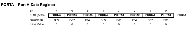
PORTA register controls whether a pin is HIGH or LOW
It is therefore équivalent to PORTA |= serial_pin_out
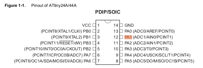
But there is another macro at line 38 that says #define serial_pin_out (1 << PA1)
It is therefore equivalent to PORTA |= (1 << PA1)
Still looking into the datasheet, we can figure out who is PA1. This is the port marked 12 on the HW representation)
The << symbol is a the "left bit shifting symbol" and here is what it does: it shifts each bit in its left-hand operand to the left by the number of positions indicated by the right-hand operand. But ... why so much pain and trouble ? Could we just set the value ?
No, and here is why: we are playing with individual bits, not decimal values. PA1 is defined in another .h file somewhere (iotnx4.h) as equal to 1. This is a decimal value, i.e 00000001 in binary representation. Thus, left shifting 0000001 by 0000001 gives 0000010... which is.. 2 in decimal
The last step is to apply the |= operator. Another programmer trick: it means "replace the content of the PORTA bit array by the result of the logical OR operation between the current value of PORTA and the value we just computed, i.e 0000010.
As a final result, we end up with an updated PORTA data register where the 7th bit is set to 1, all others remaining untouched
Note: at line 198, there is another instruction with a similar logic but with an effect on the DDR register that controls whether a pin is an input or an output
Using the Arduino IDE and libraries
I'm familiar with the Arduino IDE for a while, mainly with Arduino UNO boards but if you are not, you should have a look on the following tutorial
I found out a library written by Spence Konde here . It helps a lot to program various AVR MCUs from the Arduino IDE. There are many ways to install it, I suggest to have a look to this tutorial but there are a few things to understand to have a clear view on the big picture:
- When you get a MCU from your supplier, by default, it does (close to )nothing, there is no embbeded code on it. You have to program it. A Bootloader is the first program which executes (before the main program) whenever a system is initialized. It is used on a PC to boot the OS of the system. In case of microcontrollers, a bootloader enriches the capabilities of the microcontroller and makes them self programmable device. There are multiple ways to "burn" it (i.e to send a piece of SW to the MCU and to store it somewhere in a permanent way) it and one option is to use an external programmer (like the ISP we reproduced in the first weeks of Fab Academy). The bootloader is basically a .hex file that runs when you turn on the board
- With commercial off-the-shelf boards (like a Arduino UNO), you may notice there is apparently no need to connect a ISP and to program your MCU. You just connect the board to a USB cable and you start coding in the Arduino IDE. There is a trick: a bootloader has been burnt before the shipping and it does two things. First, it looks around to see if the computer is trying to program it (over USB). If it is, it grabs the program from the computer and uploads it into the ICs memory (in a specific location so as not to overwrite the bootloader). That is why when you try to upload code, the Arduino IDE resets the chip. This basically turns the IC off and back on again so the bootloader can start running again. If the computer isn't trying to upload code, it tells the chip to run the code that's already stored in memory. Once it locates and runs your program, the Arduino continuously loops through the program and does so as long as the board has power.
- From the library point of view, here is how the ATTiny44 looks like:
As you can see, the pins to control the LED and the button are now D8 (digital 8) and D7 (digital 7). Setting D8 to HIGH should turn the LED on and here is the code to do it
We COULD take a different path from here. The first step is to burn a specific Bootloader that will help us later to program our MCU over the FTDI cable. Connect your ISP to the board and to your computer. Start the Arduino IDE, then open the Tools menu and select a programmer (mine is a USBASP). Then select a Board (ATTiny 24/4/84) and a Chip (ATTiny44). Click on Brn Bootloader and you should see an output similar to this one. You now have a working Bootloader. Type the dmesg command in a terminal and you should see
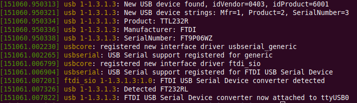
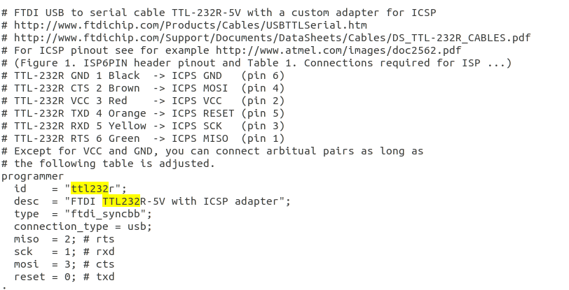
We have now a bootloader on the board. The MCU is also connected to another 6 pin connector that brings VCC, GND, Tx and Rx and we COULD use it to push our code directly using the FTDI cable and WITHOUT the ISP. But there is an issue: rigth of the bat, Arduino IDE does not know anything about our FTDI adapter... but AVRDUDE knows it, as you can see here (from /home/philippe/Documents/arduino-1.8.7/hardware/tools/avr/etc/avrdude.conf)
I will not spend more time on this but it looks it is possible. There is a file named "programmers.txt" in Arduino folders and this file set the list of supported ISPs. We could add an entry there... For the moment, I will stay on the ISP track
The next step is to create our code that the MCU will load and execute. Still using the Arduino IDE, create a new sketch. Do not change anything and click on Sketch, Uplaod to verify whether you can push code to the MCU.
Let's create another piece of code to manage the button. Two concepts are important here: debouncing and interrupts
- "Debouncing": bouncing is the tendency of any two metal contacts in an electronic device to generate multiple signals as the contacts close or open; debouncing is any kind of hardware device or software that ensures that only a single signal will be acted upon for a single opening or closing of a contact. There are many ways to manage the bouncing, at SW or at HW level. I will illustrate a possible SW solution in the code hereafter.
- "Interrupts": we don't know when someone will press the button and the main loop could be doing anything at that time. The concept of interrupt in SW is similar to the concept of "rasing your hand" in a classroom. The instructor does not want everybody to talk at the same time but he cannot ignore students neither (could he... ?). An interrupt routine ensure that no critical task will be stopped but that the request will still be handled. In a very simple program, we could just read again and again the button status very quiclky and it will work (that is what the SW guys called "polling") but when the program is bigger it becomes a mess and there is a risk to miss user input.
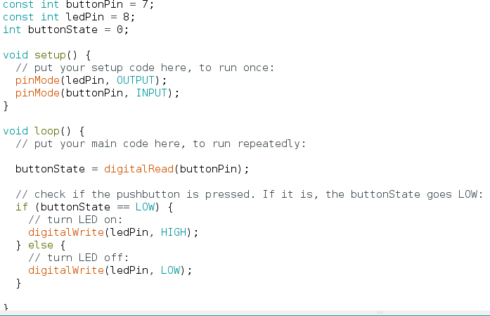
Here is how the code looks like WITHOUT interrupts and WITHOUT debouncing
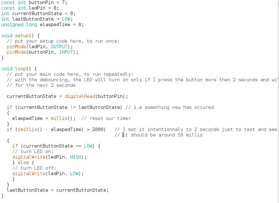
Here is how the code looks like WITHOUT interrupts and WITH debouncing
To leverage HW interrupts , we rely on the MCU specifications. Within the Hardware interrupt there are two categories: External interrupts and Pin Change Interrupts. The nomenclature here is confusing since all hardware interrupts are at first sight external. The only pin supporting external interrupts on the ATTiny44 is the pin 5 but we used it to connect the LED. In another board revision, it would make sense to use pin 5 for the button and pin 4 for the LED.
So we have to dig on the Pin change side. Each time an interrupt occurs, it triggers the associated ISR (Interrupt Service Routine) assuming you have turned that interrupt on. Each External Interrupt has its own ISR and they can be triggered independently by either a rising signal, falling signal, or by both. Note: the Pin Change Interrupts share an ISR between all the pins on a port (port B, C, and D). And anytime a pin changes on that port, it calls the port’s ISR which must then decide which pin caused the interrupt. So Pin Change Interrupts are harder to use but you get the benefit of being about to use any pin.
There are three steps to using Pin Change Interrupts.
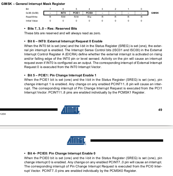
- Turn on Pin Change Interrupts is done by setting certain bits in the GIMSK register (see datasheet p49):
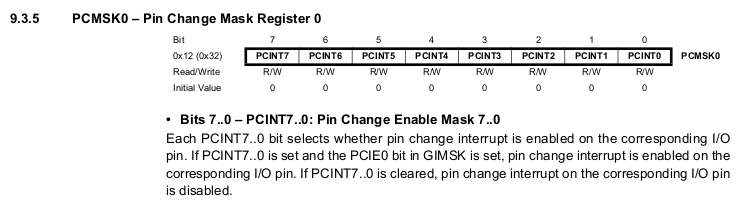
- Say (using a bit mask) which pin we want triggering this ISR by setting the PCMSK register (see datasheet p. 50). The button is connected to pin 6, ie. PCINT7 so we have to set bit 7 to 1.
- Write the ISR function (note: the ISR function manage multiple pins interrupts but since we have just one button we do not care)
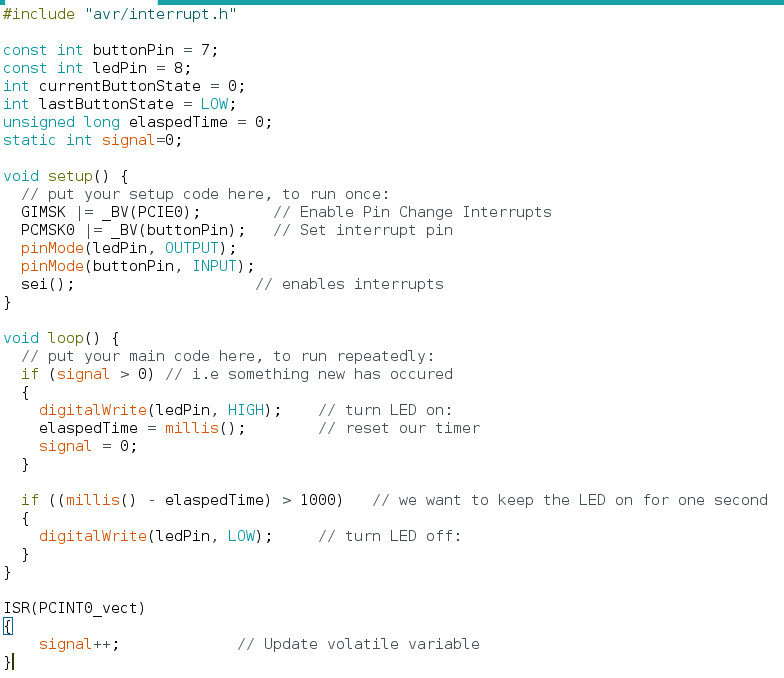
Here is how the code looks like once everything is in place
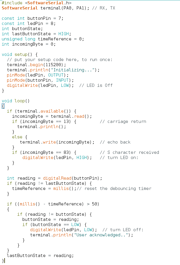
Finally, let's wrap all this and implement the required features. Note: the SoftwareSerial library is conflicting with the Interrupt library, this is a known problem I don't want to investigate now. My fallback plan is to use the SW debouncing method
Achievements
Datasheet
I'm definitely not a datasheet ninja but I understand where and what to look for
Program something
Two weeks ago, I made it work using Neil's code and this week I ran on my own with a simple scenario with a led, a button and a serial communication with a terminal
Group assignment : compare the performance and development workflows for other architectures
See here
Capstone
Still running late...
I barely can keep the current pace with a new topic every week. Stay tuned...