Input devices
Assignments
#1 - Measure something: add a sensor to a microcontroller board that you have designed and read it
To start, I will design a platform, based on the "satshakit" but with 3.3V support. I will reuse it for the coming weeks, to minimize component waste. On the top, I will design a shield/mezzanine. That part will be specific to each week. This week, I will support a RFID card reader as an input device.
#3 - Group assignment - Probe an input device’s analog levels and digital signals
References
Lecture
This week is about electronics and more specificaly abour all kind of inputs:
- Designing a main board using KiCad
- All you need to know about RFID technology, cards and card readers
- Designing a mezzanine board using KiCad
- Milling, soldering and testing the boards using SRM-20 and the reflow oven
- Programming the firmware using Arduino IDE
- Testing the entire system
Recitation
This is about
Topics covered (course) Video recording (course) Students and Labs My filesLearnings
Designing the main board
My starting point is the satshakit, an improved and fabbable Arduino compatible board, based on the ATMEGA328P mcu.
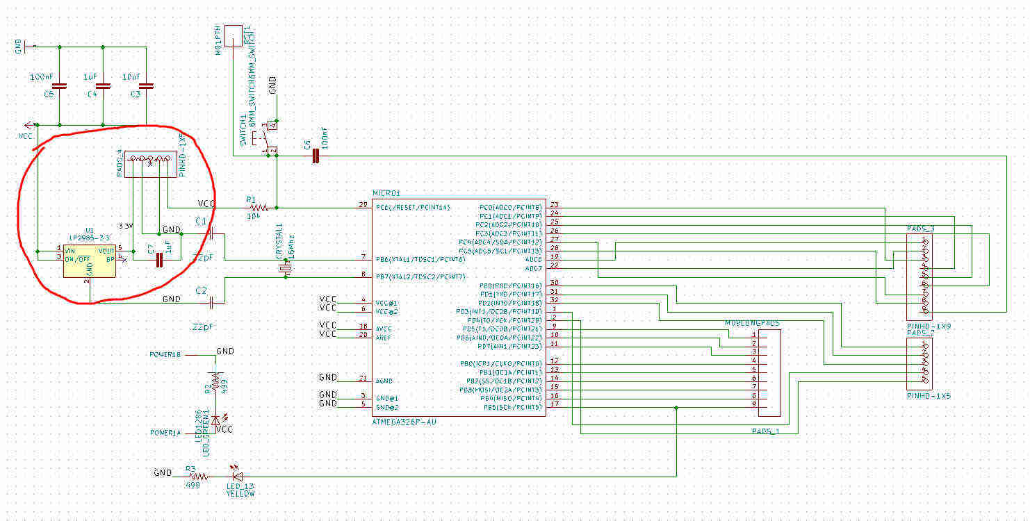
In order to feed and communicate with the RFID card reader, I need 3.3V, which is not supplied by the satshakit. I have to update the schematic to add a regulator. Here is how it looks like
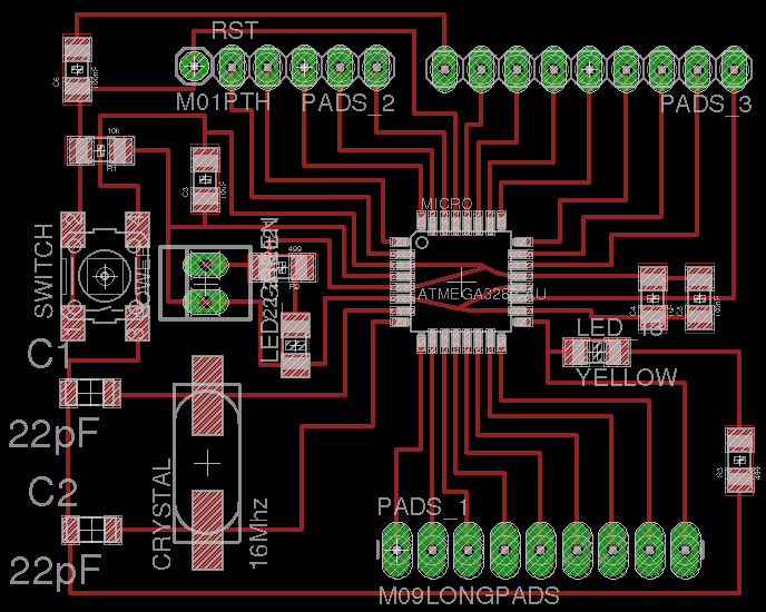
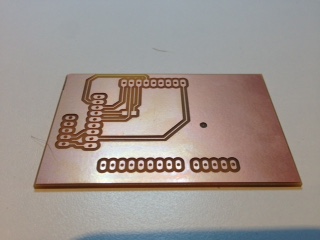
I need an additionnal connector to pass the 3.3v to the mezzanine board as well. Here is how the modified pcb looks like
All you need to know about RFID technology, cards and card readers
Most of my information comes from this site. Here are the main topics:
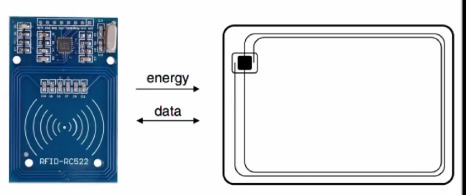
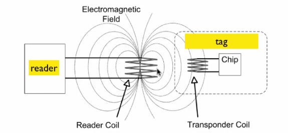
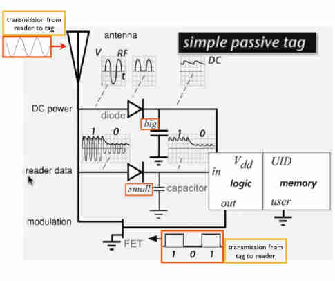
- The RFID card/tag has no source of energy by itself. The reader coil generates an electromagnetic field into the coil of the card/tag. It powers but also transmit data.
- The reader emits a carrier wave that is (amplitude) modulated width the transmitted data.The backscattered signal is modulated as well to pass the information back to the reader
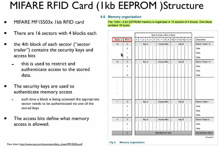
- The passive card I will be using is based on the MIFARE standard (use for cash cards or building access) The card contains 1kB of encryptable memory and oparates at a distance of 1-2 cm to the reader.
Designing the mezzanine board
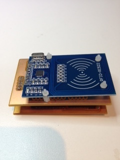
I designed a mezzanine board for two reasons: first, to be able to reuse the common part (the modified satshakit) for next weeks and second to map the card interfaces to the satshakit connectors
As mentionned earlier, the card requires 3.3V and made it possible by adding a regulator to the satsahkit.
As per the datasheet, it looks I need also a logic lever converter as well, otherwise I will dammage the card reader when setting any digital pin to HIGH. Here is how to solve this. That smart design will convert each HIGH signal in both directions according to the voltage supported by the target.
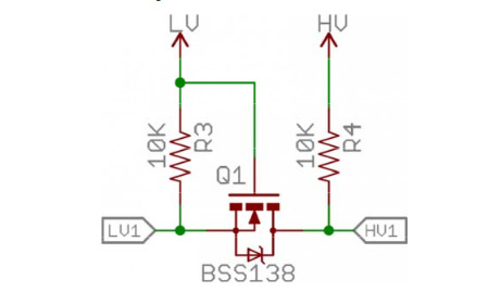
This is based on a Sparkfun product. Here is the pcb of this product. As you can see, there is no way to implement this on a single side pcb, there is at least one via, approximatively on the middle on the picture.
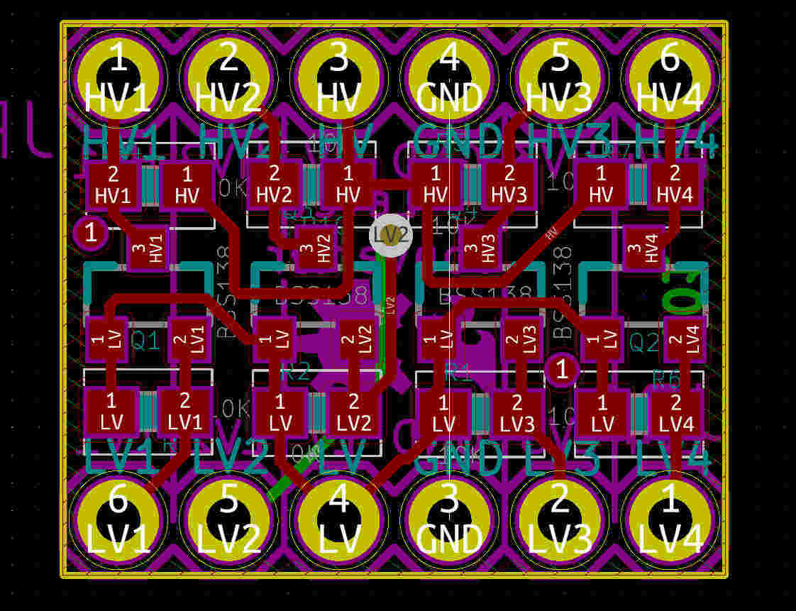
It is a little bit to much for this week to start designing a double side PCB (but be sure I will come back to that challenge later ! ) and , HOPEFULLY, the card reader is "5V tolerant". (not from the power supply point of view but only from the digital pins point of view)
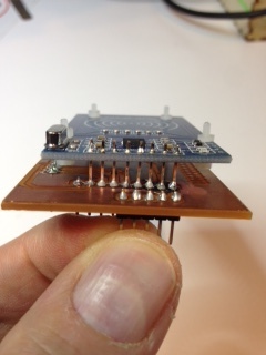
The schematic is quite simple and here is how the pcb looks like. The only trick is the 0 oHm resistor I used to create a small bridge and avoid a double side board
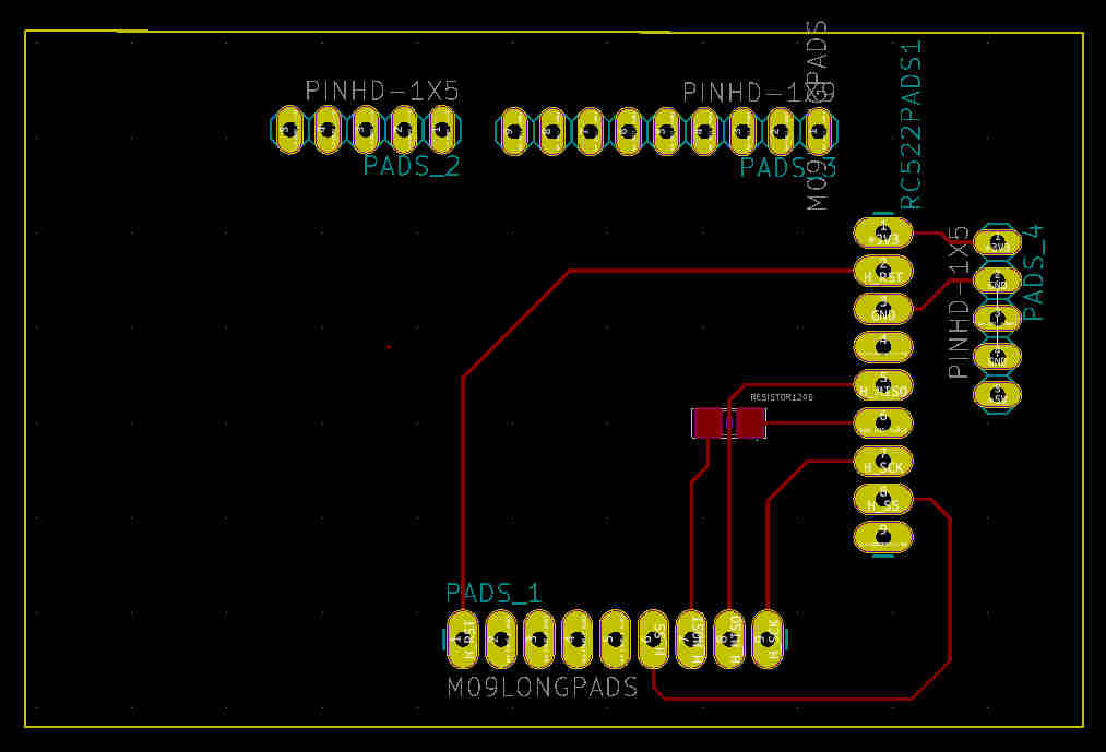
One last thing to mention: I don't know how to draw and export the drill layer in KiCad and I finaly made all the drills using a portable drill after the milling phase on SRM-20
Milling, assembling and soldering the boards
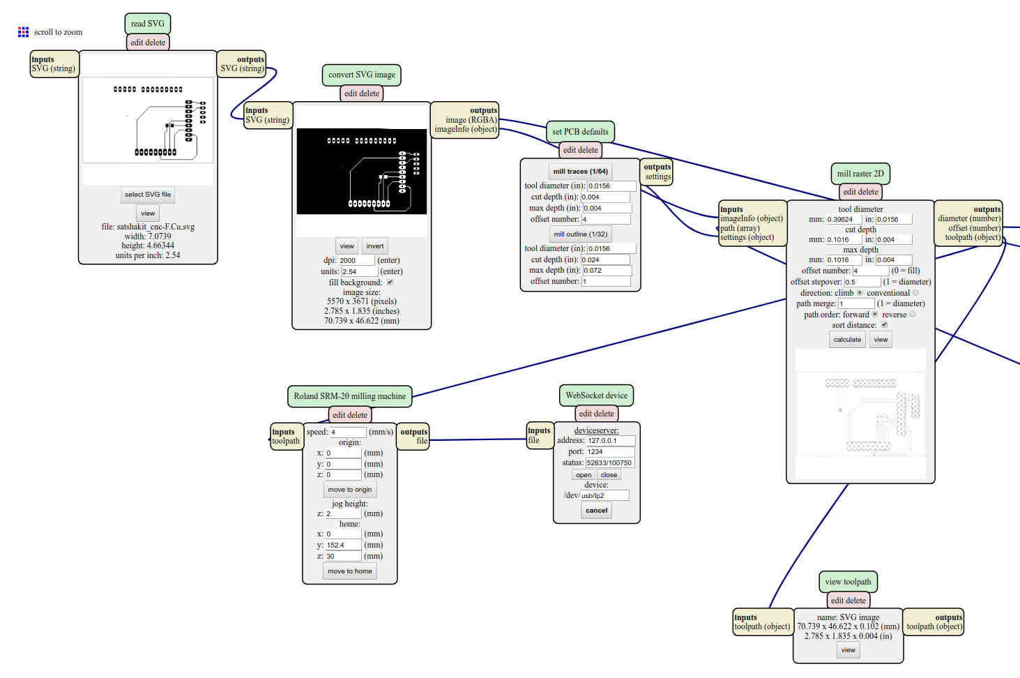
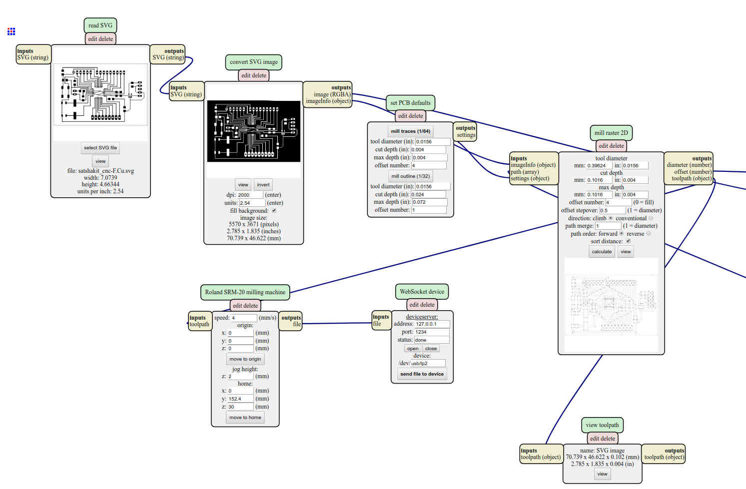
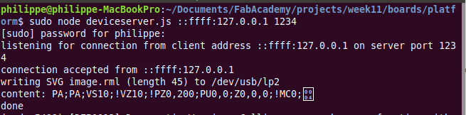
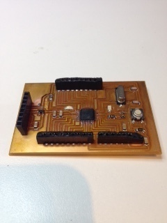
This is now a routine procedure and here is the pipeline, including the output of the gateway between the mods and the SRM-20 under Linux (looks Mum, no hands !) and the output
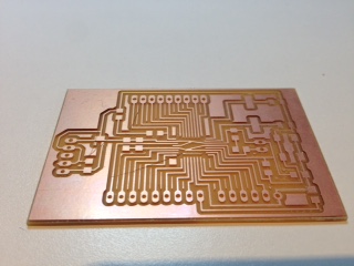
And now.... the moment when something goes WRONG
Everything is fine with my home made reflow oven (but maybe the strange look of my pcbs) but the discovery for this week is...
... sometimes, a component is not designed to be oven reflowed .. and it melt. So are the cheap connectors ! and here is why the final product looks ... (dont't say.. )
Programming the firmware
In the beginning, there was nothing. And God said, “Let there be light.” And there was light. There was still nothing, but you could see it a lot better. (Woody Allen)
Just the day after came the .. bootloader (my humble contribution)
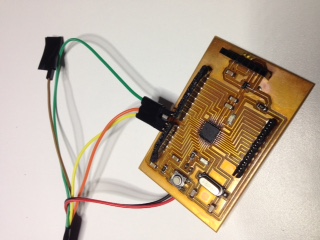
Same story we learned at week #5, we have to push a small piece of code using an ISP to the MCU. Here is how to connect an ISP
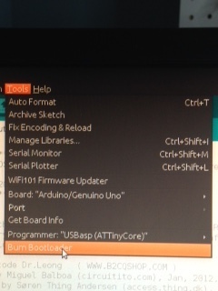
Once the bootloader is... well .. loaded... there is no need to use the ISP. We can leverage the FTDI cable and to use it to push any application code (and to get access to the serial console to see outputs at the same time)
For this week assignment, I just want to read a card or a tag and display what is stored in it in a terminal. Here is the program:
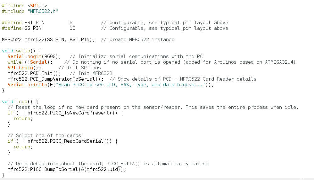
- I'm using a library written by Miguel Balboa library for MFRC522 and other RFID RC522 based modules. The 2 first lines are references to that library and to a standard libraries used to communicate over SPI.
- MFRC522 mfrc522(SS_PIN, RST_PIN); // Create MFRC522 instance, i.e initialize the library and make it ready to communicate with the RC522
- SPI.begin(); // Init SPI bus, we need this to allow the library to communicate with the RC522. The MFRC522 acts as a slave during SPI communication (as per the datasheet). The SPI clock signal SCK must be generated by the master. Data communication from the master to the slave uses the MOSI line. The MISO line is used to send data from the MFRC522 to the master. Data bytes on both MOSI and MISO lines are sent with the MSB first. Data on both MOSI and MISO lines must be stable on the rising edge of the clock and can be changed on the falling edge. Data is provided by the MFRC522 on the falling clock edge and is stable during the rising clock edge.
- mfrc522.PCD_Init(); // Init MFRC522. If you check the code for that function ( here , you will see it does quite a long list of tasks: set pins state and ensure the communication is established with the RC522 and set a long list of registers (see pages 36 in datasheet)
- mfrc522.PCD_DumpVersionToSerial(); // Show details of PCD - MFRC522 Card Reader details. This is just to display the firmware version , i.e the code that runs on the RC522
- From now, we have everything in place to be able to read a card or a tag and we have to wait for the user to scan it. That's basically what the main loop does.
- if ( ! mfrc522.PICC_IsNewCardPresent()) {return; // if there is no card in front of the reader, just do nothing. The way to do this is to send the Request command, type A, to the RC522. Sending a command is done by setting a value in a register (as explained on page 38)
- if ( ! mfrc522.PICC_ReadCardSerial()) { return; // if the card is being read, just do nothing... wait and come back later. To do this, the library checks whether a UID can be read. If it is the case, then it assumes there is valid information available for reading
- mfrc522.PICC_DumpToSerial((mfrc522.uid)); // here we read the information stored in background while reading the card (it takes seconds to go through all the data slots) and we display the content on screen
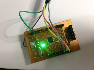
Testing the entire system
Giving more details on the structure of the information read on the card is out of scope for this week. I just tried with a RFID card and a RFID tag and here are the outputs
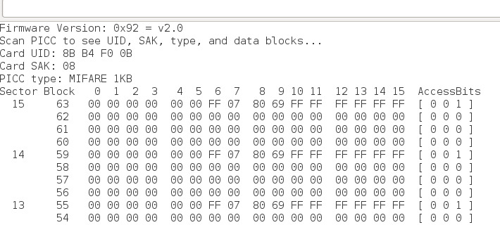
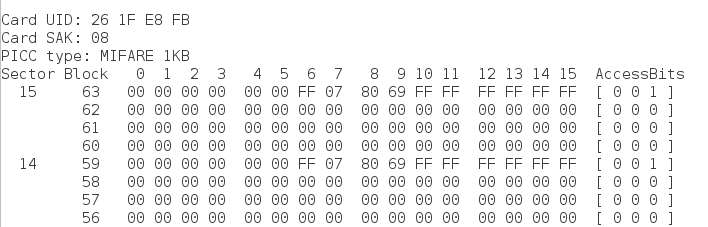
And here is how to interpret it
Achievements
#1 -Measure the analog levels and digital signals in an input device
See here
Capstone
#1 -Tampering sensor
I did not touch that part of the design this week
#1 -NFC card reader
It is mainly done. From now, I know how to interact with the card reader and how to get the card ID from a RFID card or tag