Output devices
Assignments
#1 - Add an output device to a microcontroller board you've designed, and program it to do something
For my capstone project, I need an OLED screen. I will leverage the platform board designed last week and create another mezzanine board
#2 - Measure power consumption
References
Lecture
This week is about electronics and more specificaly abour all kind of outputs:
- All you need to know about OLED screens
- Designing a mezzanine board using KiCad
- Milling, soldering and testing the mezzanine board using SRM-20 and the reflow oven
- Programming the firmware using Arduino IDE
- Testing the entire system and measuring power consumption
Recitation
This week is about the various foundations, organizations and infrastructure that are "behind the curtain" to make all this great adventure possible
Topics covered (course) Video recording (course) Video recording (recitation) Students and Labs My filesLearnings
OLED screens
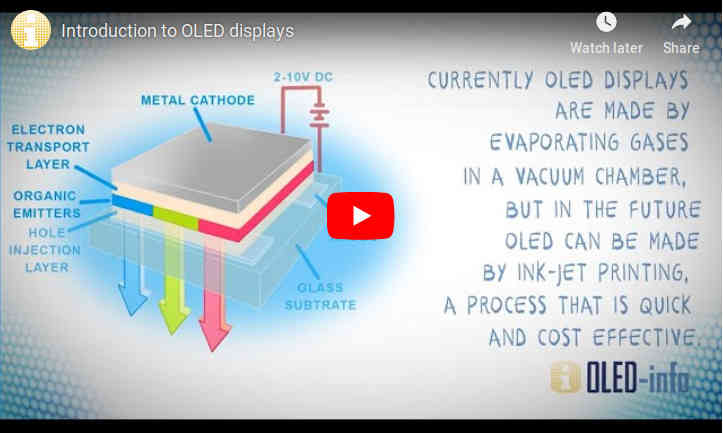
An organic light-emitting diode (OLED) is a light-emitting diode (LED) in which the emissive electroluminescent layer is a film of organic compound that emits light in response to an electric current. This organic layer is situated between two electrodes; typically, at least one of these electrodes is transparent.
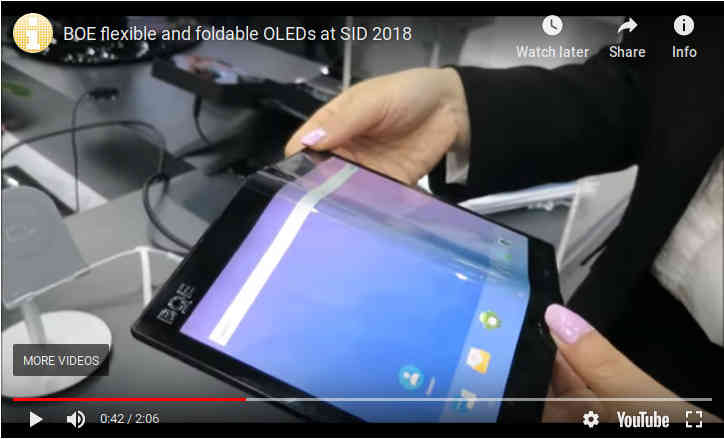
Foldable OLED displays are exciting - as these displays will enable new device form factors - such as phones that open into tablets, smart bands that open into smartphones and more. In 2019 we will finally see the first foldable smartphones on the market!
At short term and .. at an affordable cost, there are nice small OLED screen you can get for a few $ and I bought one to integrate to my capstone project
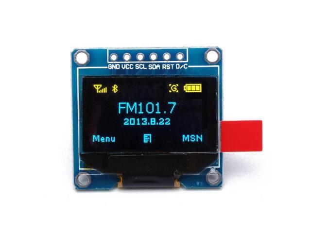
There are (at least) 4 pins to connect the OLED board to our MCU: GND, VCC and two for I2C communication.
(from Sparkfun) The Inter-integrated Circuit (I2C) Protocol is a protocol intended to allow multiple "slave" digital integrated circuits ("chips") to communicate with one or more "master" chips. Like the Serial Peripheral Interface (SPI), it is only intended for short distance communications within a single device. Like Asynchronous Serial Interfaces (such as RS-232 or UARTs), it only requires two signal wires to exchange information. Each I2C bus consists of two signals: SCL and SDA. SCL is the clock signal, and SDA is the data signal. The clock signal is always generated by the current bus master; some slave devices may force the clock low at times to delay the master sending more data (or to require more time to prepare data before the master attempts to clock it out). This is called "clock stretching" and is described on the protocol page.
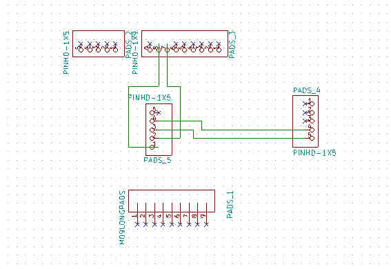
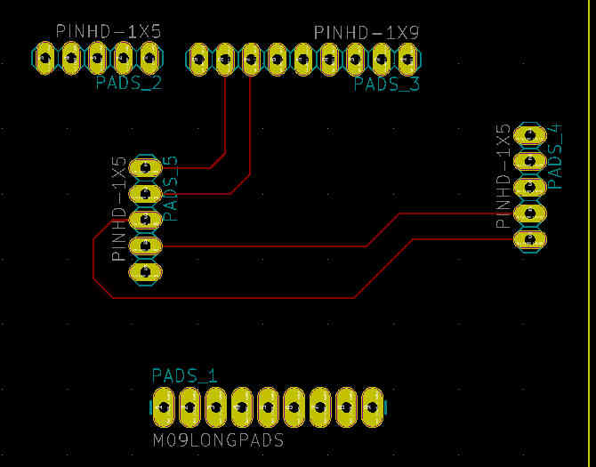
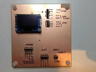
Designing the mezzanine board for the OLED screen using KiCad
The schematic is quite simple: no active component, just a few traces to route the 4 pins to the right place on the platorm board/
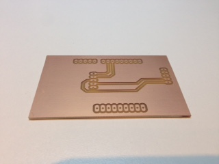
Milling, soldering and testing the mezzanine board
This is the exact same process as last week/
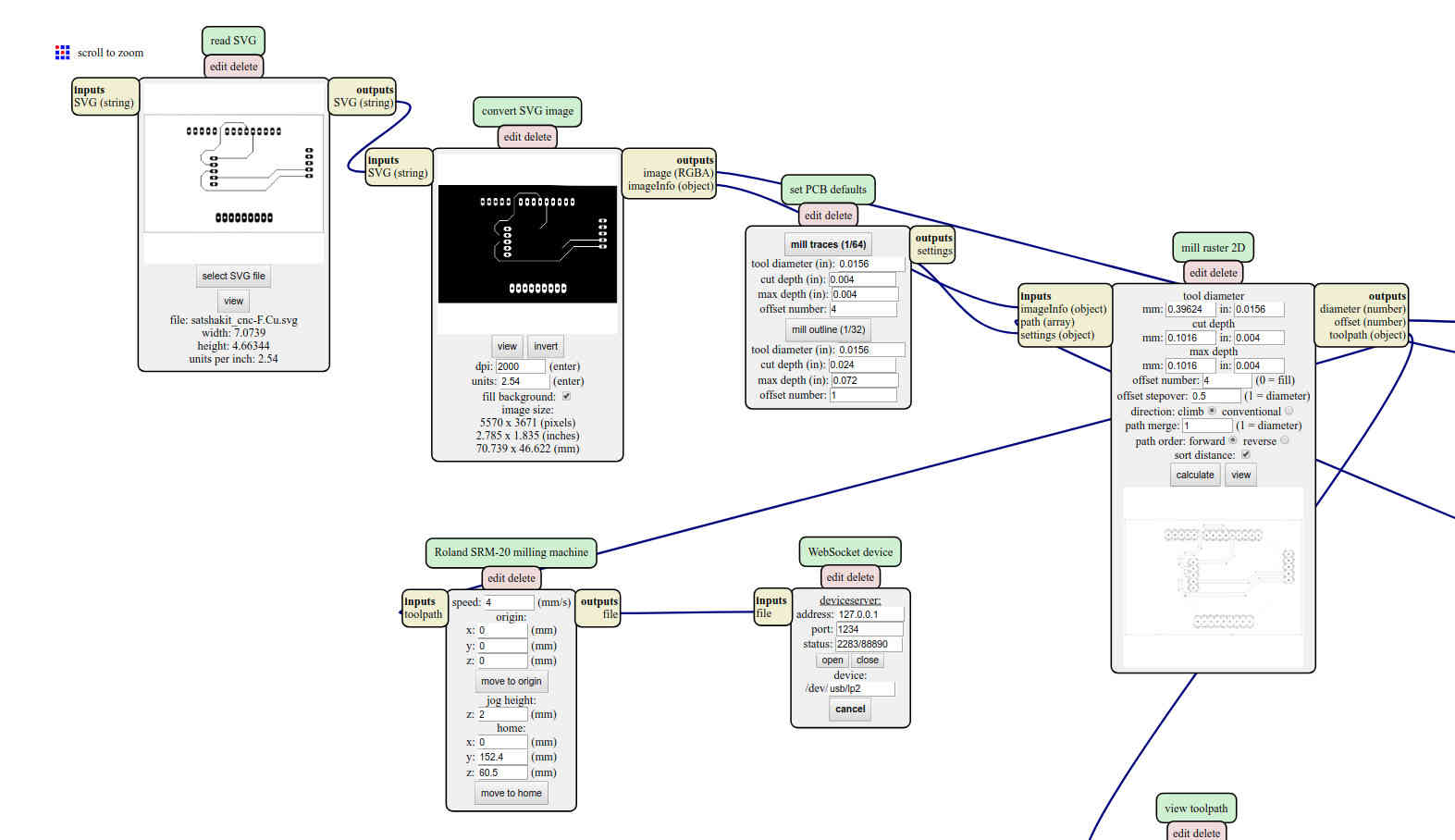
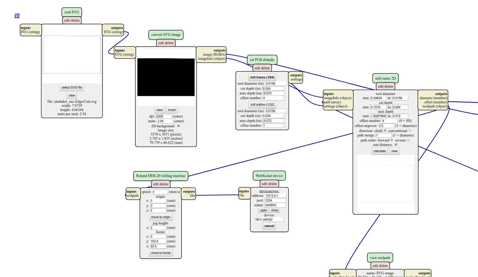
Note: I'm still searching how to get the drill map out of KiCad and how to use it (idealy using the mods) to drill the holes on the board
Programming the platform firmware
I'm using the Adafruit library. My screen size is 128 by 64 pixels. You can use them individualy to display a picture or use pre-built funtions to display text in various size.
As explained on Adafruit web site, Pixels — picture elements, the blocks comprising a digital image — are addressed by their horizontal (X) and vertical (Y) coordinates. The coordinate system places the origin (0,0) at the top left corner, with positive X increasing to the right and positive Y increasing downward

Coordinates are always expressed in pixel units; there is no implicit scale to a real-world measure like millimeters or inches, and the size of a displayed graphic will be a function of that specific display’s dot pitch or pixel density. If you’re aiming for a real-world dimension, you’ll need to scale your coordinates to suit. Dot pitch can often be found in the device datasheet, or by measuring the screen width and dividing the number of pixels across by this measurement.
Here is how display a simple message
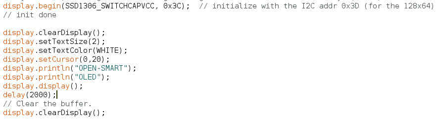
Here are more details on the code (see here to get the full code for this example
- I'm using a Adafruit library for Monochrome OLEDs based on SSD1306 drivers. The 4 first lines (not shown here) are references to that libraray (in fact two libaries, one generic to graphics and another one specific to OLED screens) and to standard libraries used to communicate over I2C and SPI. On my board, I will be using I2C and therefore the "wire" library
- display.begin(SSD1306_SWITCHCAPVCC, 0x3C); // initialize with the I2C addr 0x3D (for the 128x64)
- display.clearDisplay(); // clear the entire display. The library will reset a memory buffer. That memory buffer is an array of hexadecimal values (we need hexa to be able to display info on color-capable displays), with one element for each pixel we could address. We have a screen with 128 pixels horizontaly and 64 verticaly. Screen dimensions are 128 by 64 pixels and pixel coordinates start at 0, 0 for the top left pixel. This means that the X coordinates for the screen are from 0 to 127 (not 1 to 128) left to right; and Y coordinates are from 0 to 63 (not 1 to 64) top to bottom.
- display.setTextSize(2); // Before writing text to the display, we call setTextSize() to set ... well .. the text size and then setTextColor(). Because this is a monochrome display, setTextColor() must be passed WHITE for the text to be seen on a black background."
- display.setCursor(0,20); // Text that is written to the display is positioned to move the invisible cursor to the desired position. X and Y coordinates are passed to setCursor() to move the cursor and start of text to these pixel coordinates.
- display.println("OPEN-SMART"); // prepare the text to be displayed.
- display.display(); // All text and graphics are written to buffer memory. This means that any text and graphical objects such as lines and circles will not appear on the screen until display() is called.
There are primitives in the library, to draw a line for example. But we are limited with the screen resolution and what looks like a line will be in reality a set of pixels, like shown here


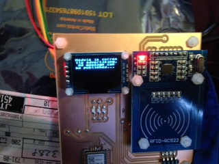
Testing the entire system
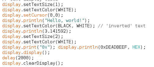
This is a proof of concept where I play with text size and color inversion
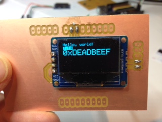
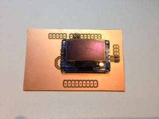
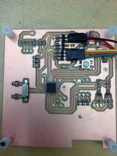
The mezzanine is connected to the same board I used last week. Here is how it looks like
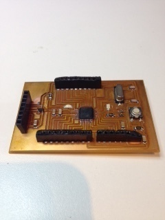
I will be using the same OLED screen for my final project (picture on the right) and for the wildcard project (picture on the left). Picture on the center is the back of the pcb of the final project
In this example, we play we the text size. The first two lines are set with a default magnification factor of 1 but the third one is set to 2.
Even with a monochrome screen, some fantasy is still possible: the second line is displayed with white text on a black background
You may ask.... how does it work to display a letter, like "A" on the screen, assuming it is in fact just a wide array of pixels ? The answer is within the drawChar() function within the library. There’s only one font (to save on space) and it’s meant to be 5x8 pixels, but an optional size parameter can be passed which scales the font by this factor (e.g. size=2 will render the text at 10x16 pixels per character). All ASCII character representations are stored in a separate file in the library.

Power consumption
Regarding power consumption, there are two elements to consider:
- The MCU (and a few LEDs that are on the board)
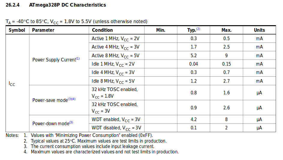
- The OLED screen. Datasheet is not easy to find but I read on this site that power consumption would not exceed 20mA when all dots are On
To compare theory and reality, I used a small USB dongle we have at my day job. Here is the measurement with the MCU only
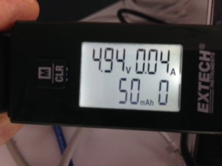
When the OLED screen is connected, it does not increase a lot. I read 52mA on the dongle but not all dots were On. Far from the 20mA...
Achievements
#1 - Design and make a simple mezzanine board
#2 - Control the OLED screen over I2C
Capstone
#1 - OLED screen
This week is my proof of concept. I know it works and how to connect it. There is another challenge in front of me: for the capstone project, I want to design a double side PCB, with the MCU part on the rear part and with the accessories (OLED, RFID card reader, ..) on the front side. I have to search more on how to do this
#2 - Solid State Relay
No progress
#3 - LEDs
No progress