
Fusion360 is a very flexible parametric CAD software.
From my perspective of a SolidWorks user, it lacks its simplicity. On the other hand, it is far more affordable, free for most of us.
I modeled the entire systems on the Model Workspace, that shows the tools you need for solid 3d parametric modeling.
in SolidWorks, you always start from a sketch (mode) on a plane and then start extruding, generating new planes in which you will be able to sketch again.
It is also very easy to maintain projects and collaborate online. The version tracking system is effective and comprehensive.
I would recommend Fusion360: A good parametric design, sharing and collaborative system for better open design.
I’ve been learning a lot from this youtube channel.
In the middle of this FabAcademy process I was invited to develop my solution in a workshop that took place in Ioannina Greece for the innauguration of a new Makerspace - Tzoumakers. The workshop took place in this newly founded place in the mountains near the city in a small town called Kálentzi. The Greek National TV also attended and it resulted on this: (see the artifact at minute 15:00 aprox)

NOTE ABOUT CAD 2D CAD 2D is here integrated in the 3D processes. but I also used it in on its own in two ocasions:
As the invitation to participate on Tzoumakers Workshop arrived it wasn’t clear for me what I would be doing there nor the relation with my ongoing Fab Academy process. The time was arriving and the organization suggested the design of a Nursery for plants it came clear that this effort optimisation was possible and very good idea.
Fusion 360 was the chosen tool since I wanted to test and learn more its workflow because it has proven itself as a very efficient adoption for my students.
Before starting I made sure the materials and big CNC were available there and started designing a solution.
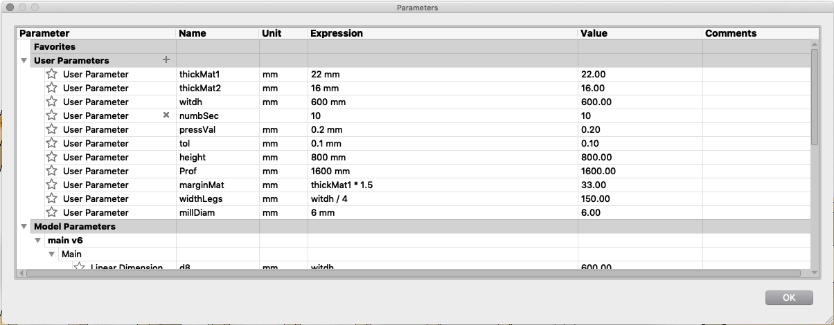
The distance imposed some parametric management, especially over variables like tolerance, main dimensions and press-fit tightness value.
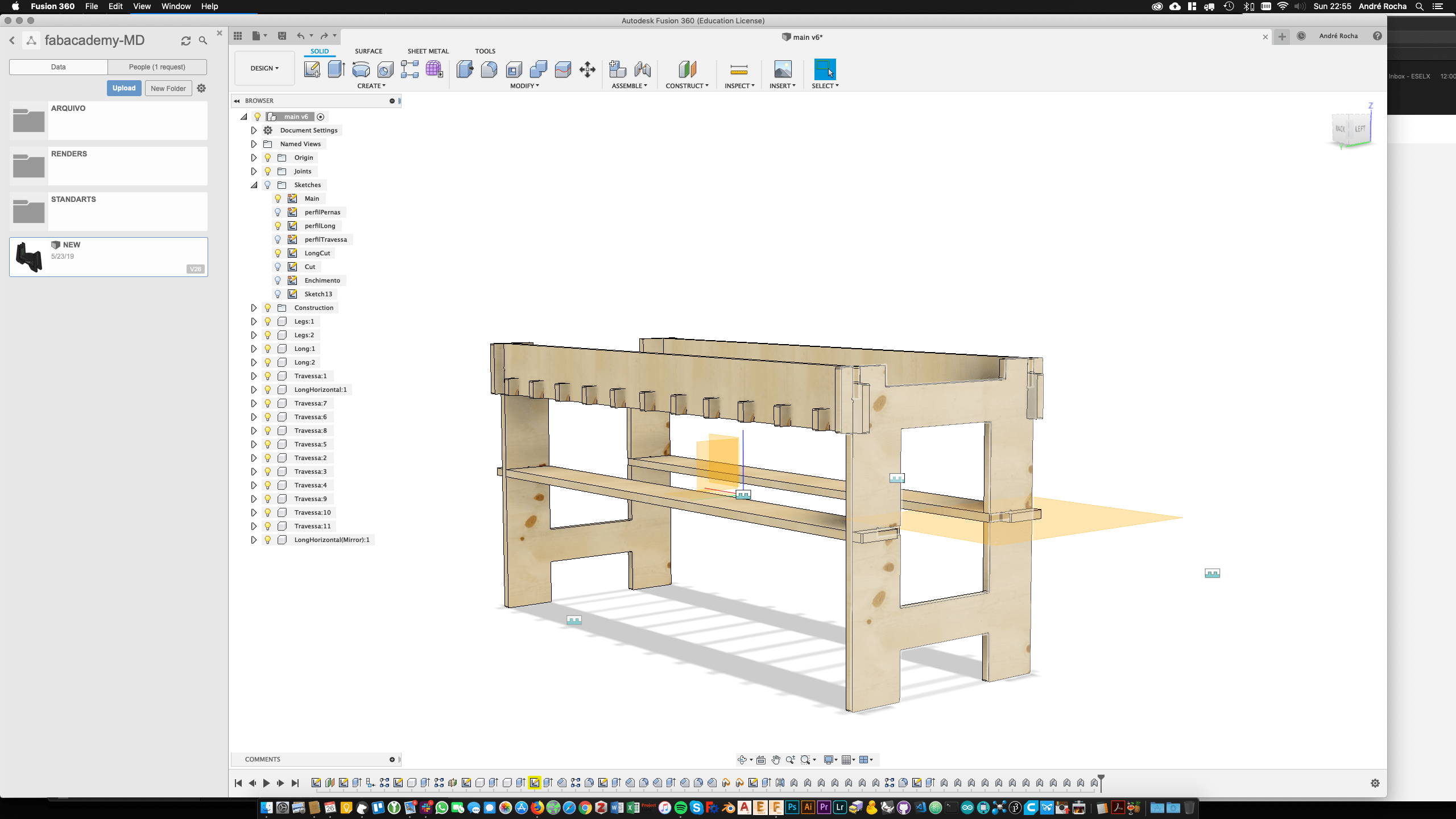
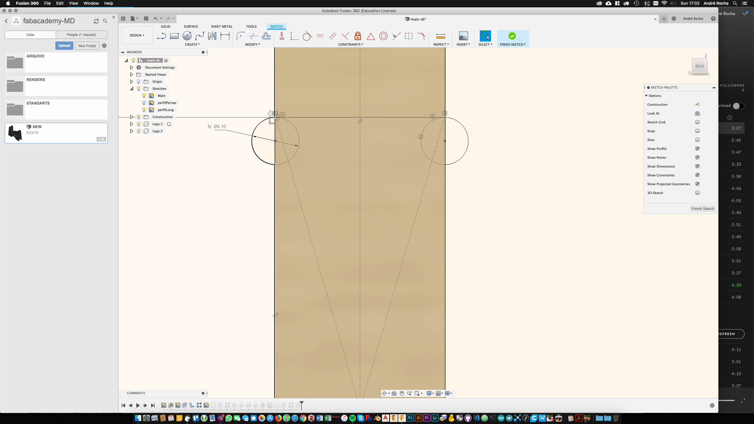
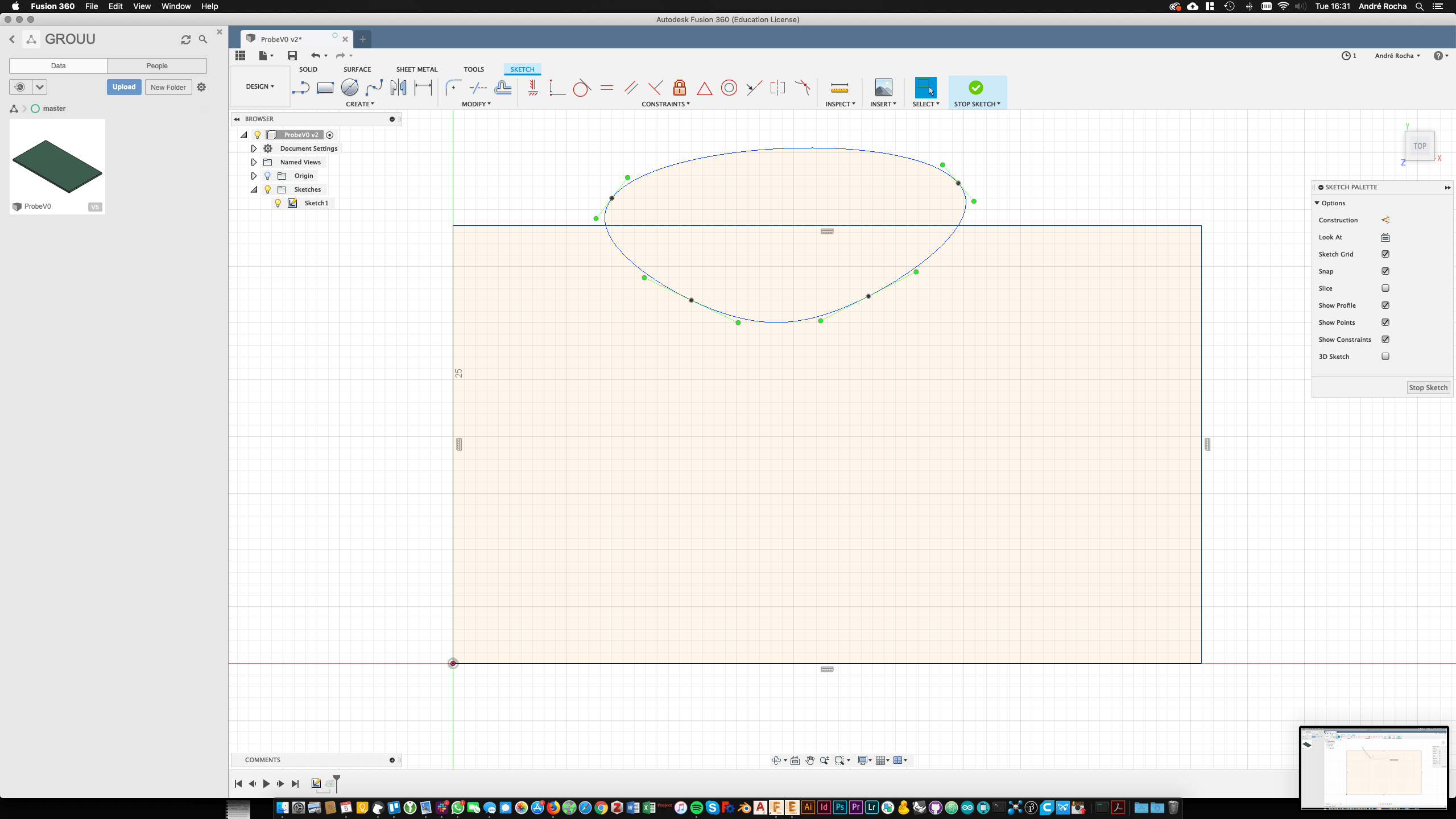
Img1 - first sketches
As in most of this kind of softwares we start by a 2D shape. I tend to create one that dictates and is influenced my the main dimensions, because afterwards I will be able to reference the shapes.
I also created some very basic dimensional sketches for reference.
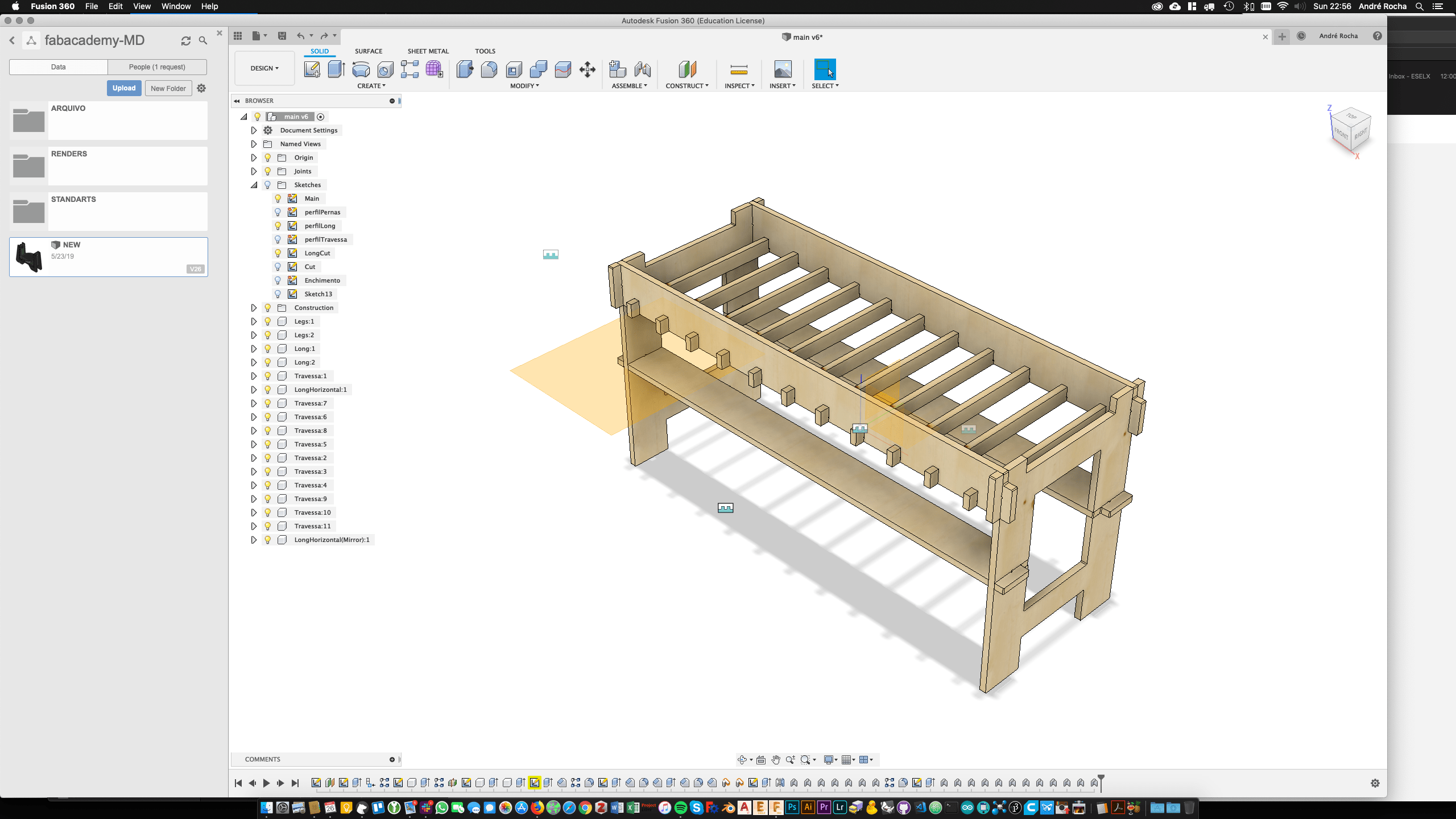
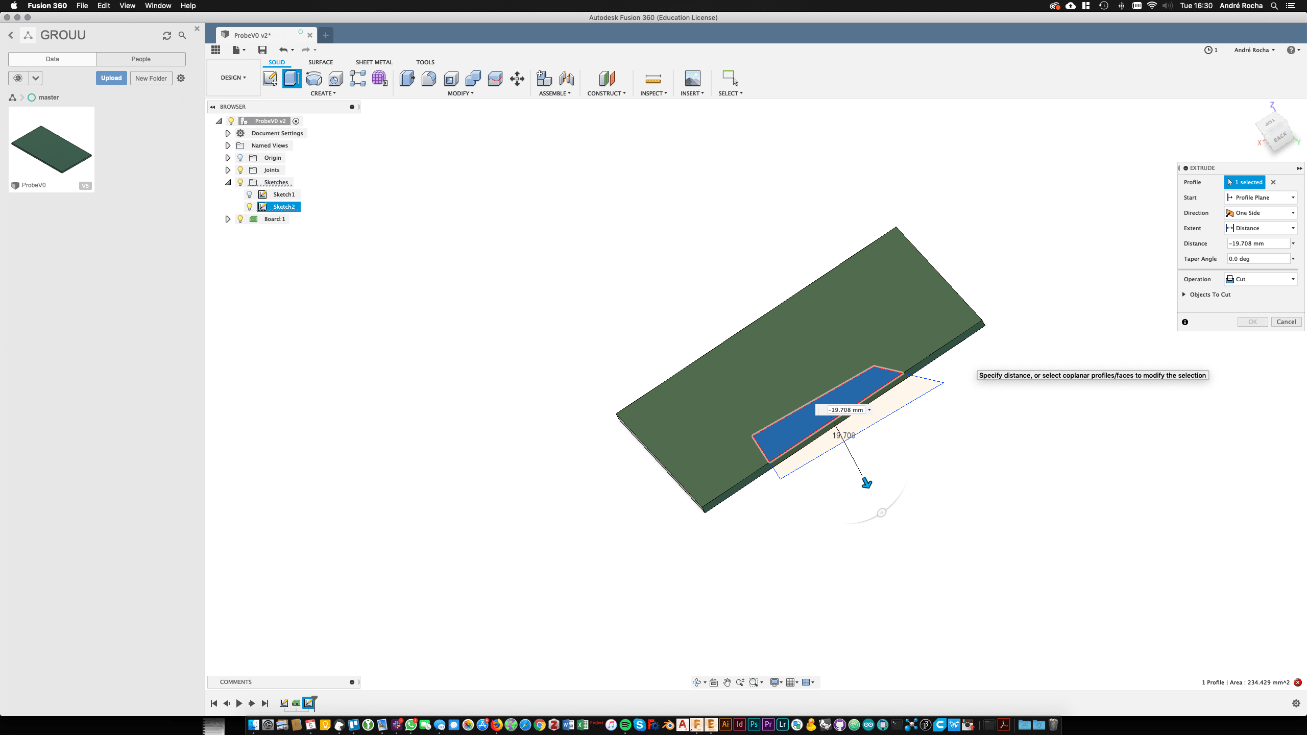
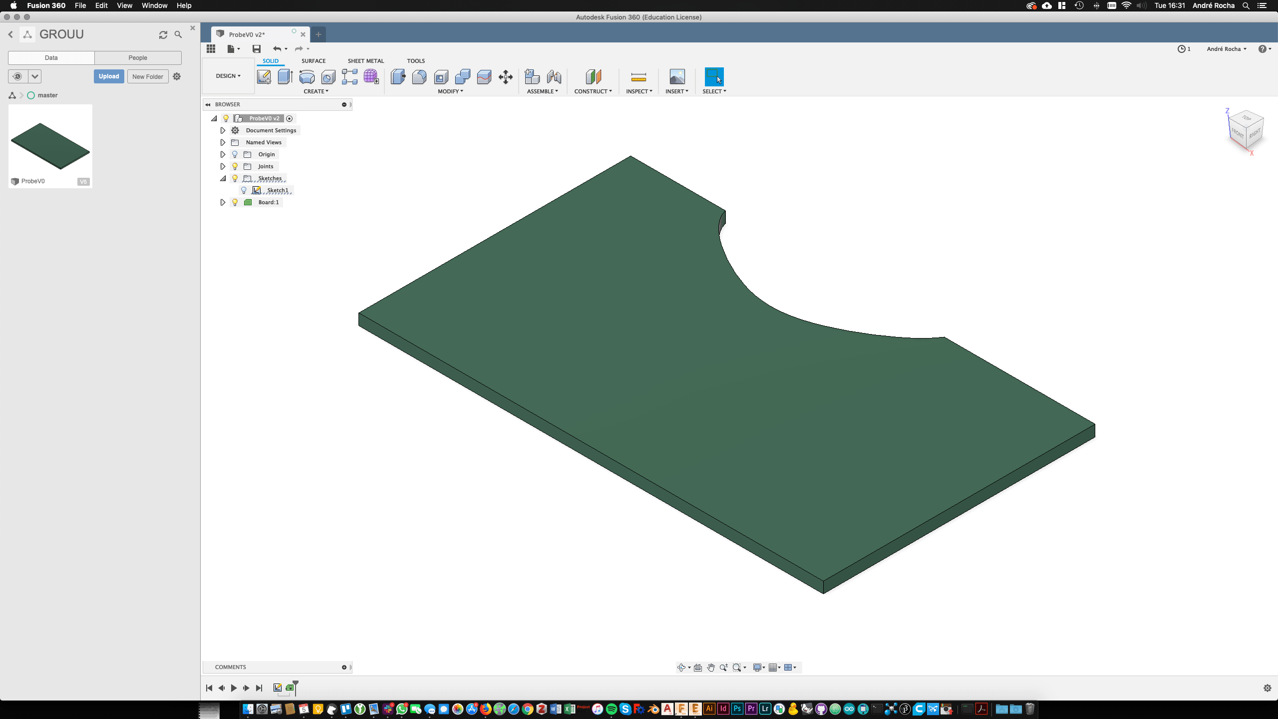
Img2 - Extrusion with dimensions and sketching again until everything is in place
A very good thing about parametric CAD design is the ability to control this kind of variables. This will be very important on the CNC milling of posterior assembly.
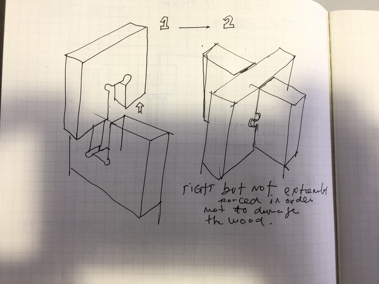
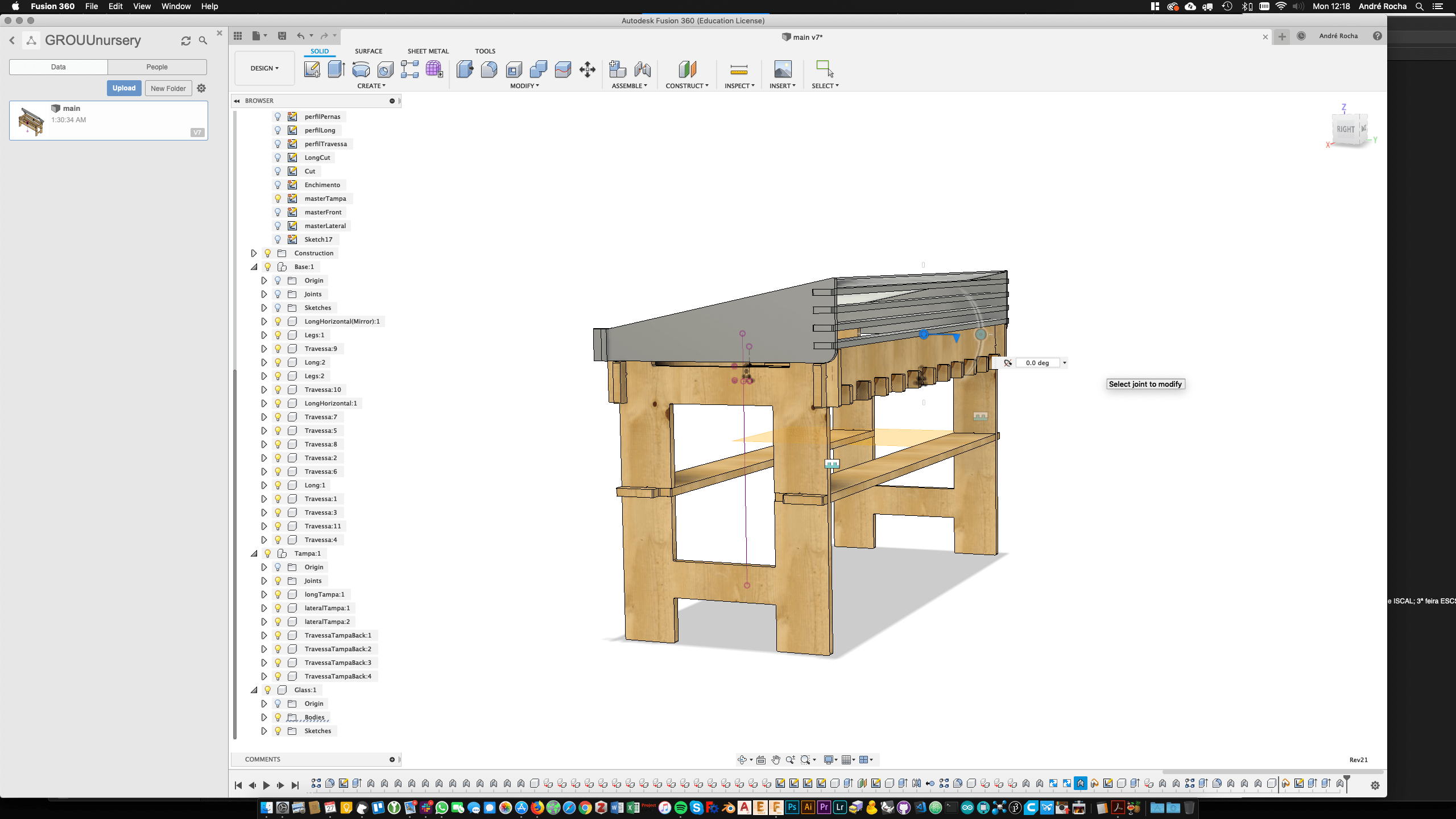
 Img3 - The joints - as you can see in the image the value “pressVal” is being used to distance the cut female part of the joint in order to press fit on the male.
After several attempts I noticed that the best way to work with this kind of objects is to design everything and then work on the joints in a systematic way. Patterns are also a very useful way of modularising the approach to design.
As a proficient solid works user, it took me some time to understand how the joints worked.
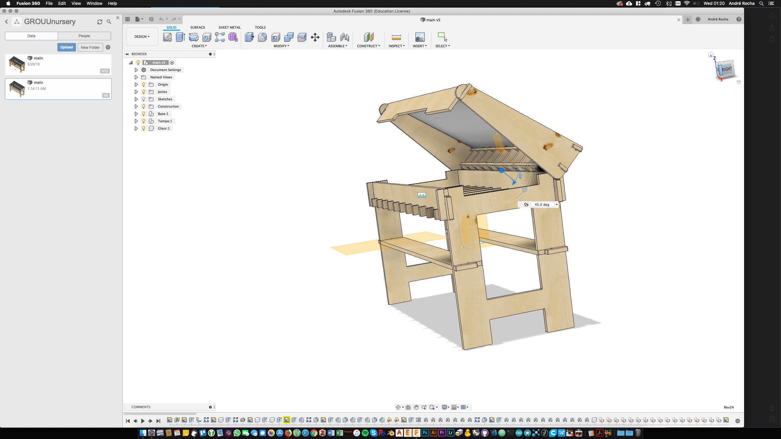
The best strategy is to design each component as is in the final position and then use the assemble_ as built joint_ option.
You can also restrict angles and check interferences on different positions.
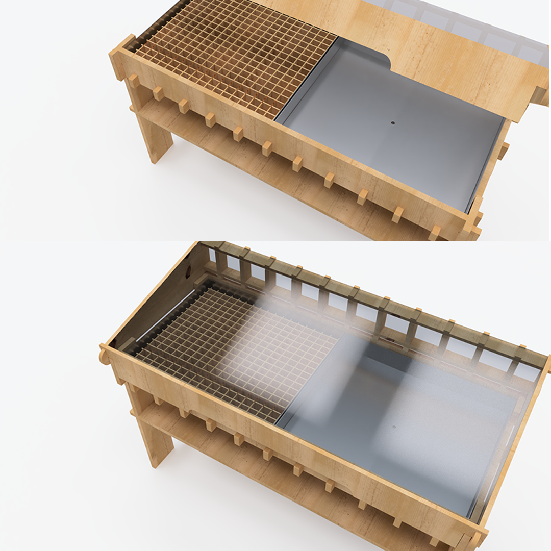
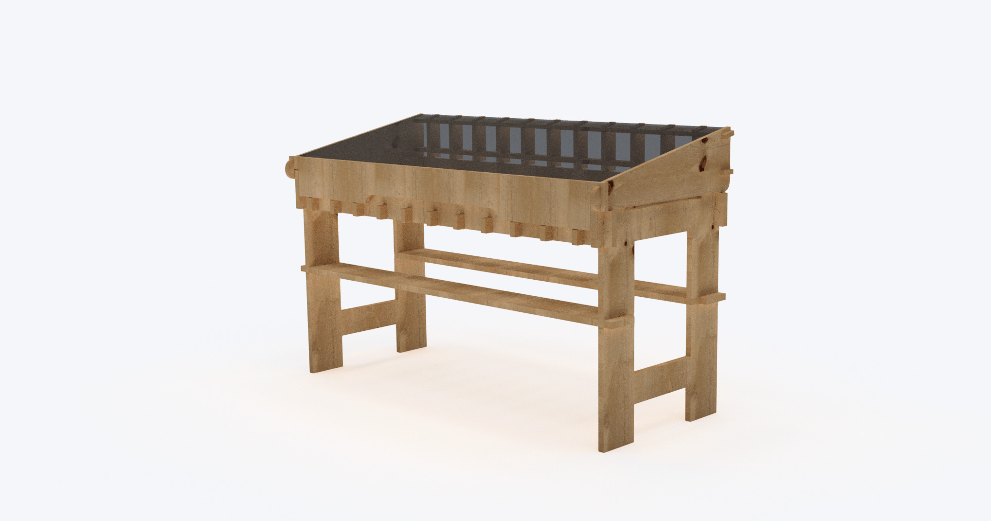
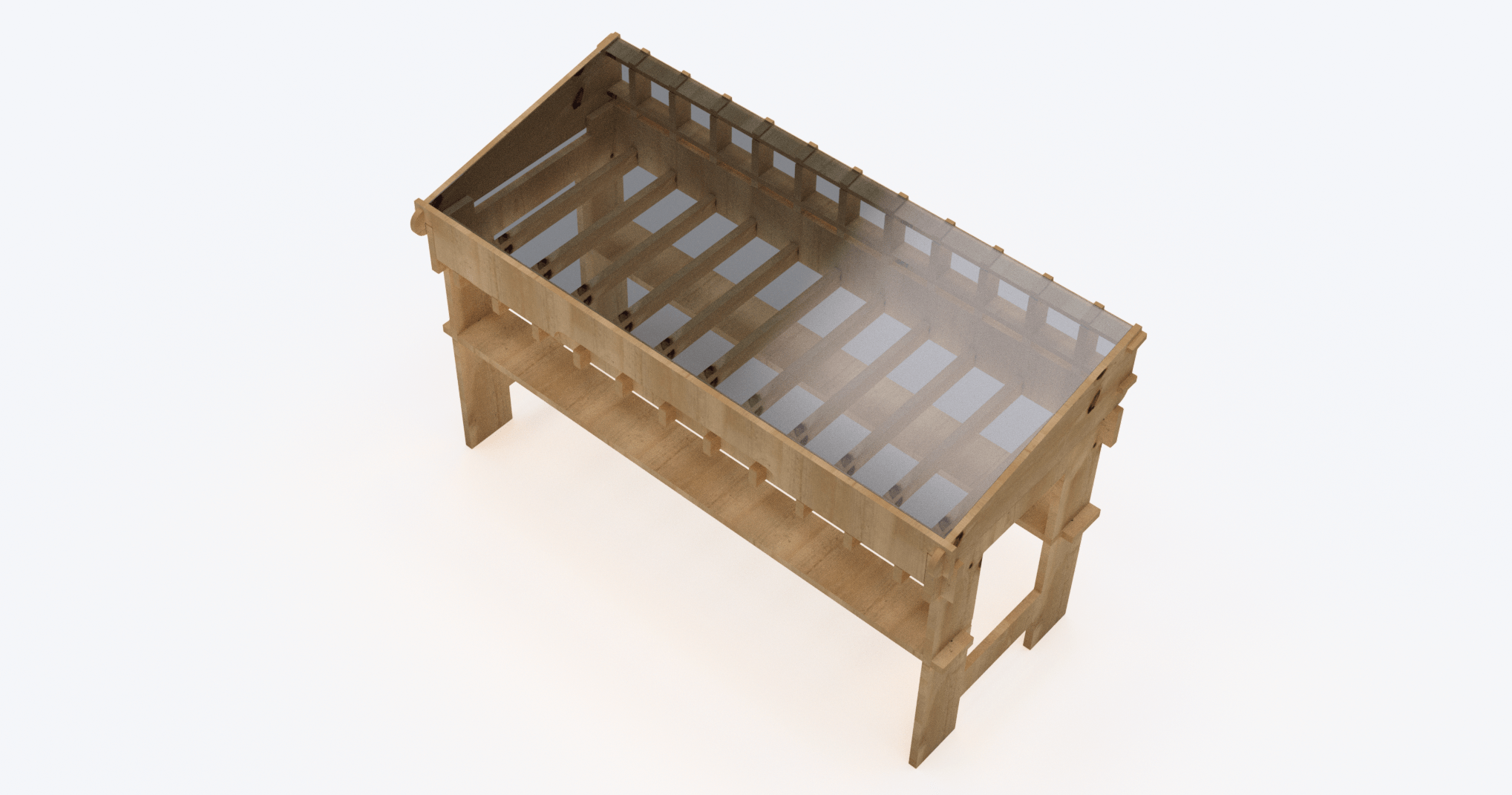
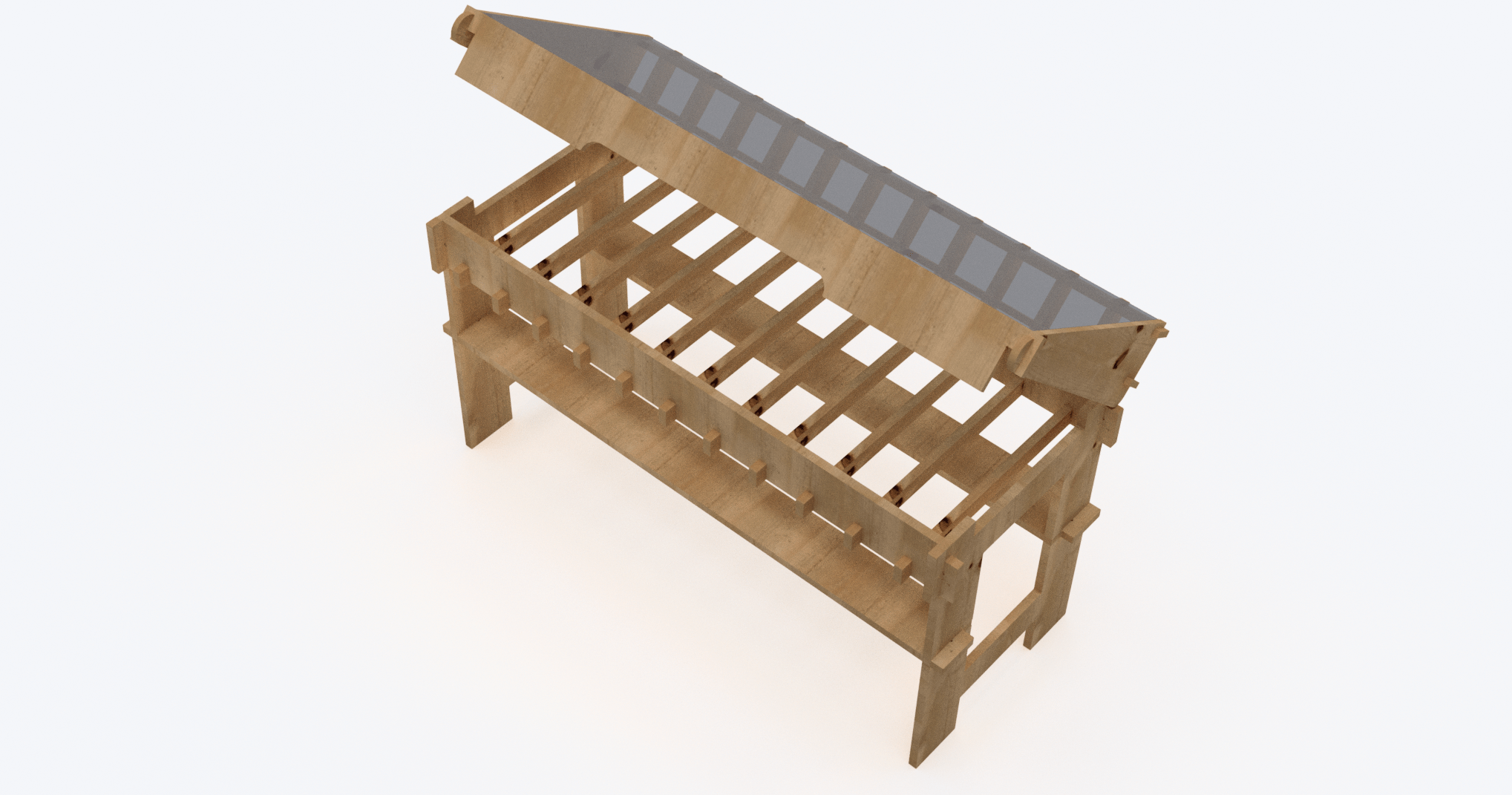
Finally the default rendering tool is very handy, quick and versatile.
Here are the renders os my first version of the Tzoumakers GROUU nursery.
This Process will explore 3D CAD through the preparation of a 3D model where the PCB (yet blank) is already integrated. By exploring the parametric world I expect to be able iterate between PCB and the rest of the design, developing both at the same time, or by just adjusting both on new versions.
Then I will start the design of some of my parts, that require integration with electronics and document it in this section, leaving a first iteration of electronics design for the input and output devices.
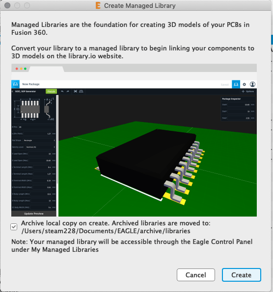
I started by looking for tutorials and found this precious introduction:
Fusion 360 Integration with EAGLE How-To | EAGLE | Blog
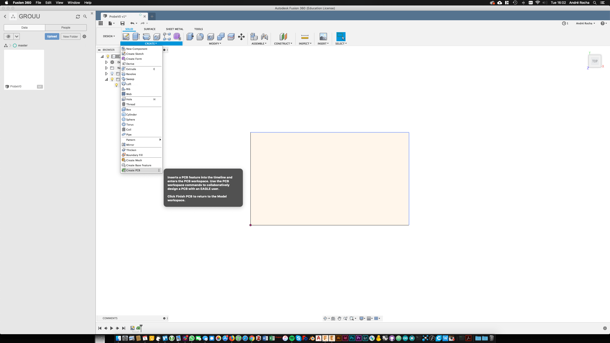
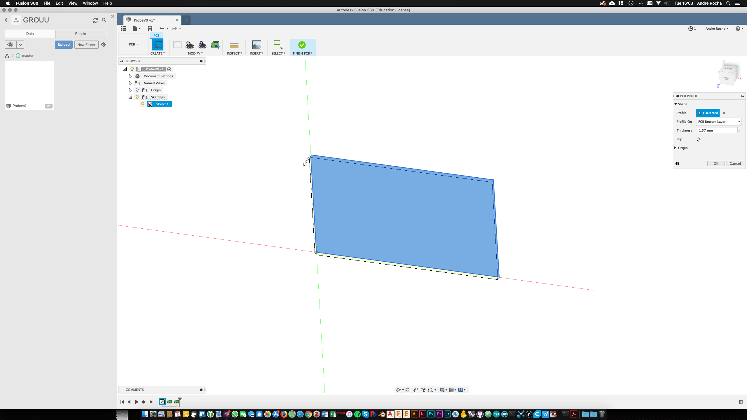
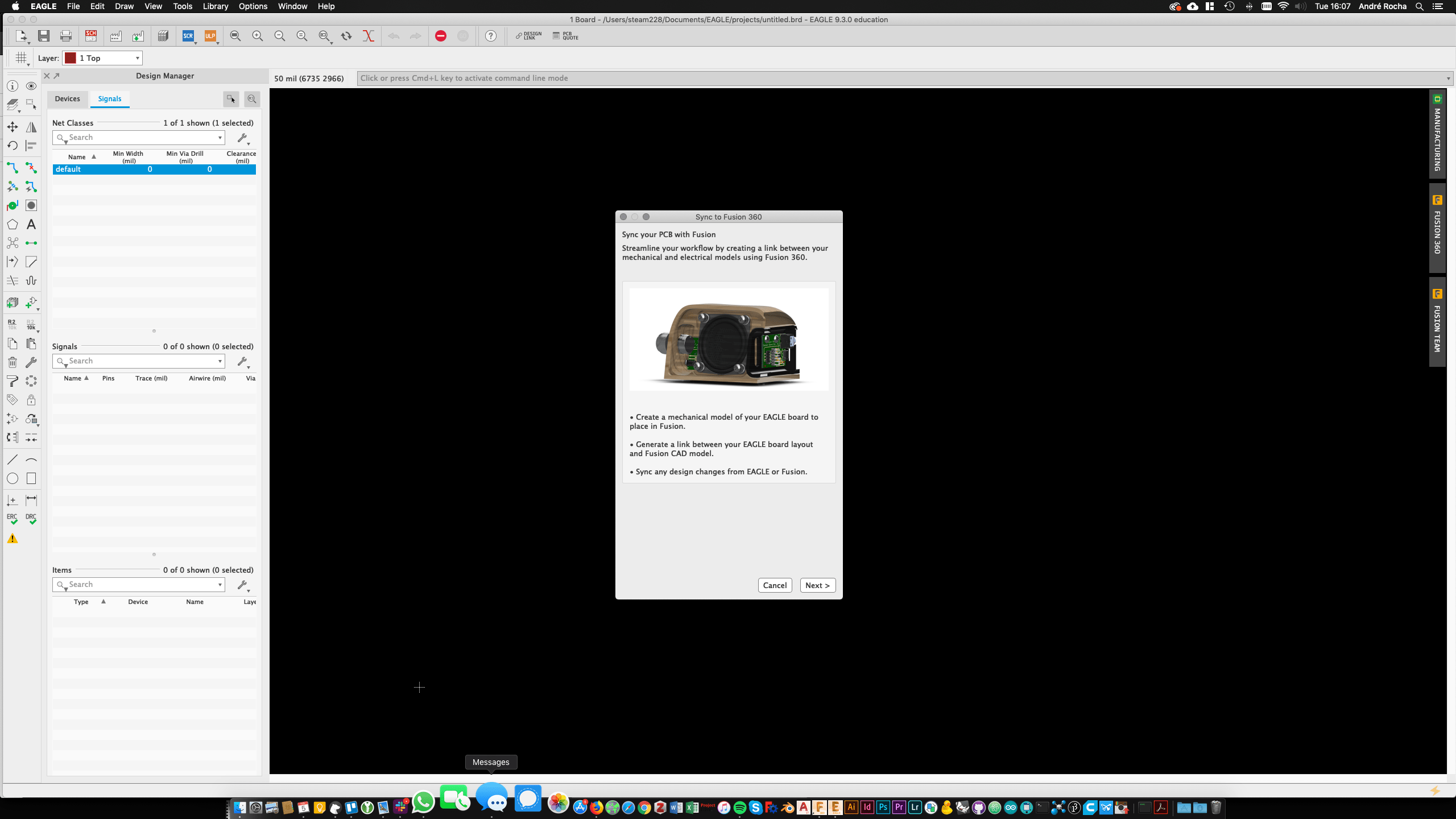
1. Creating a Basic rectangle on Fusion and making it a PCB:

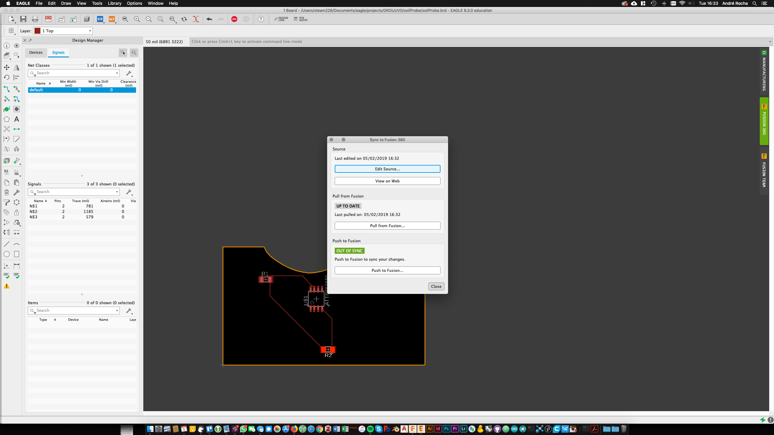
2. Syncing it with EagleCAD
3. Saving everything and creating a simple stupid schematic:
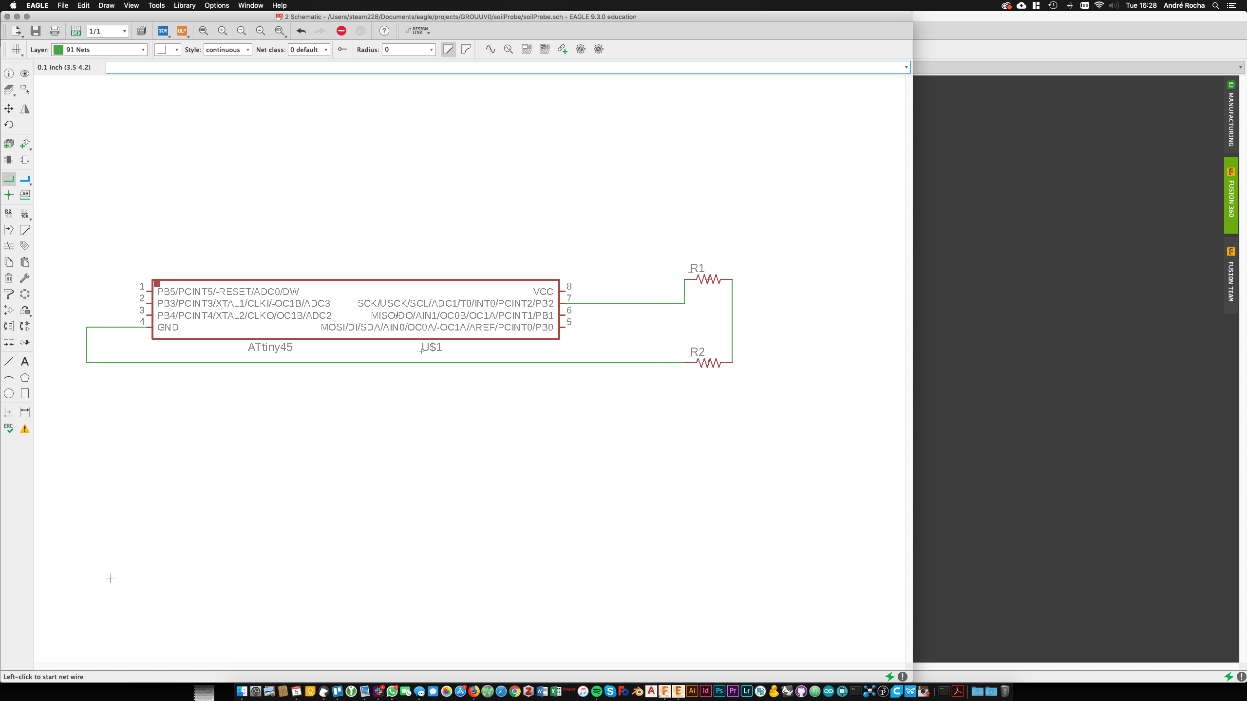
4. Switched to Board and arranged an equally stupid circuit:
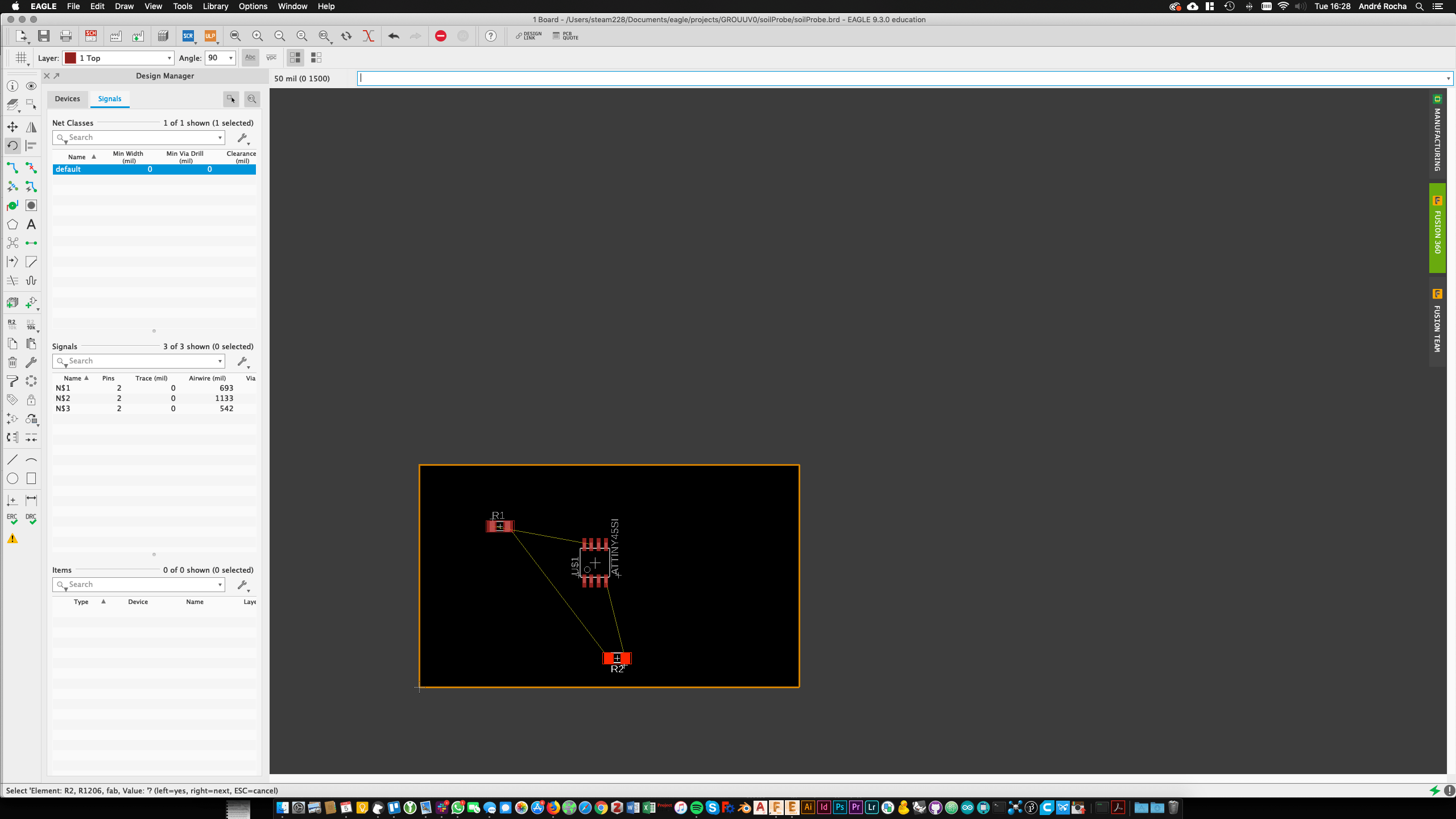
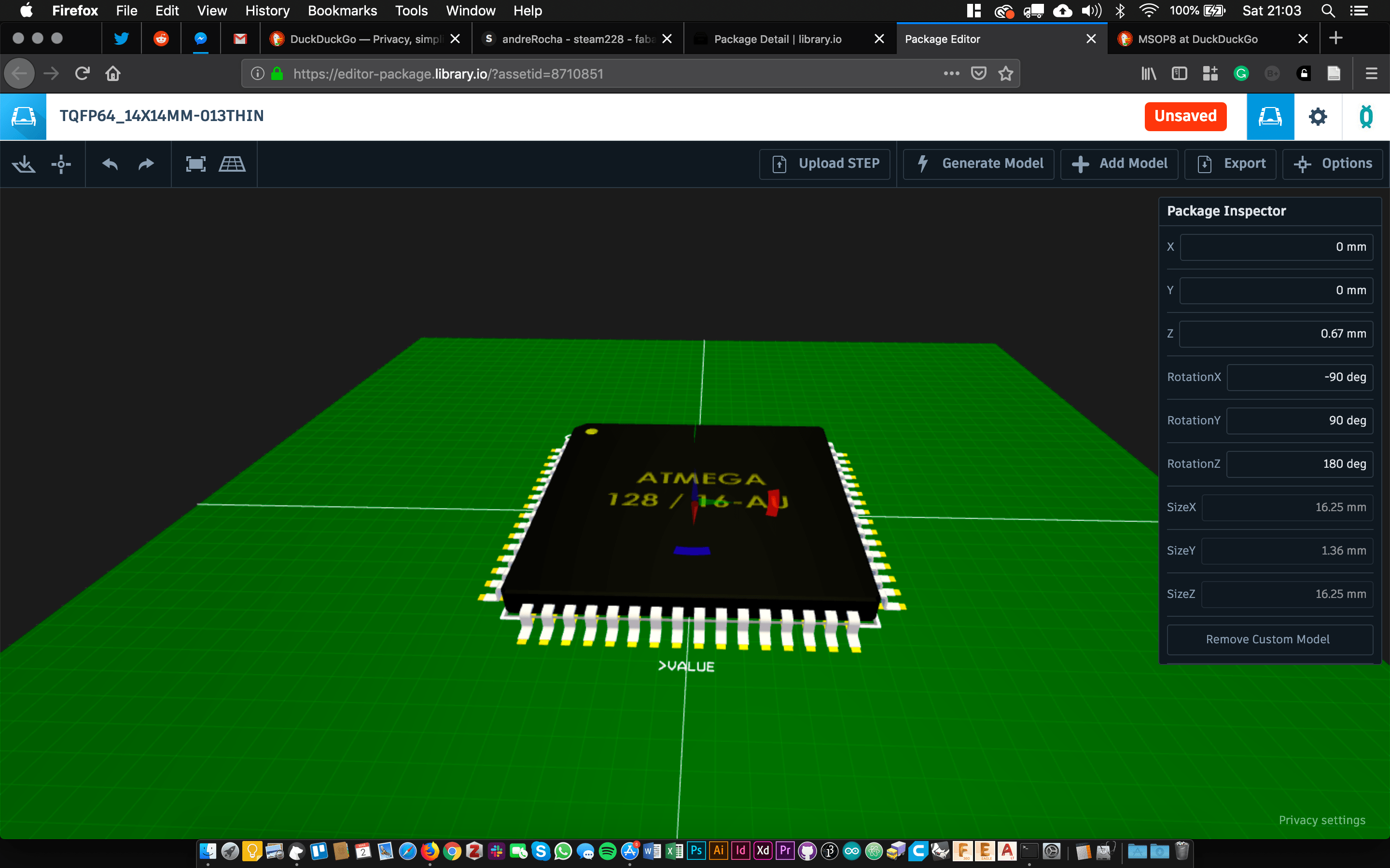
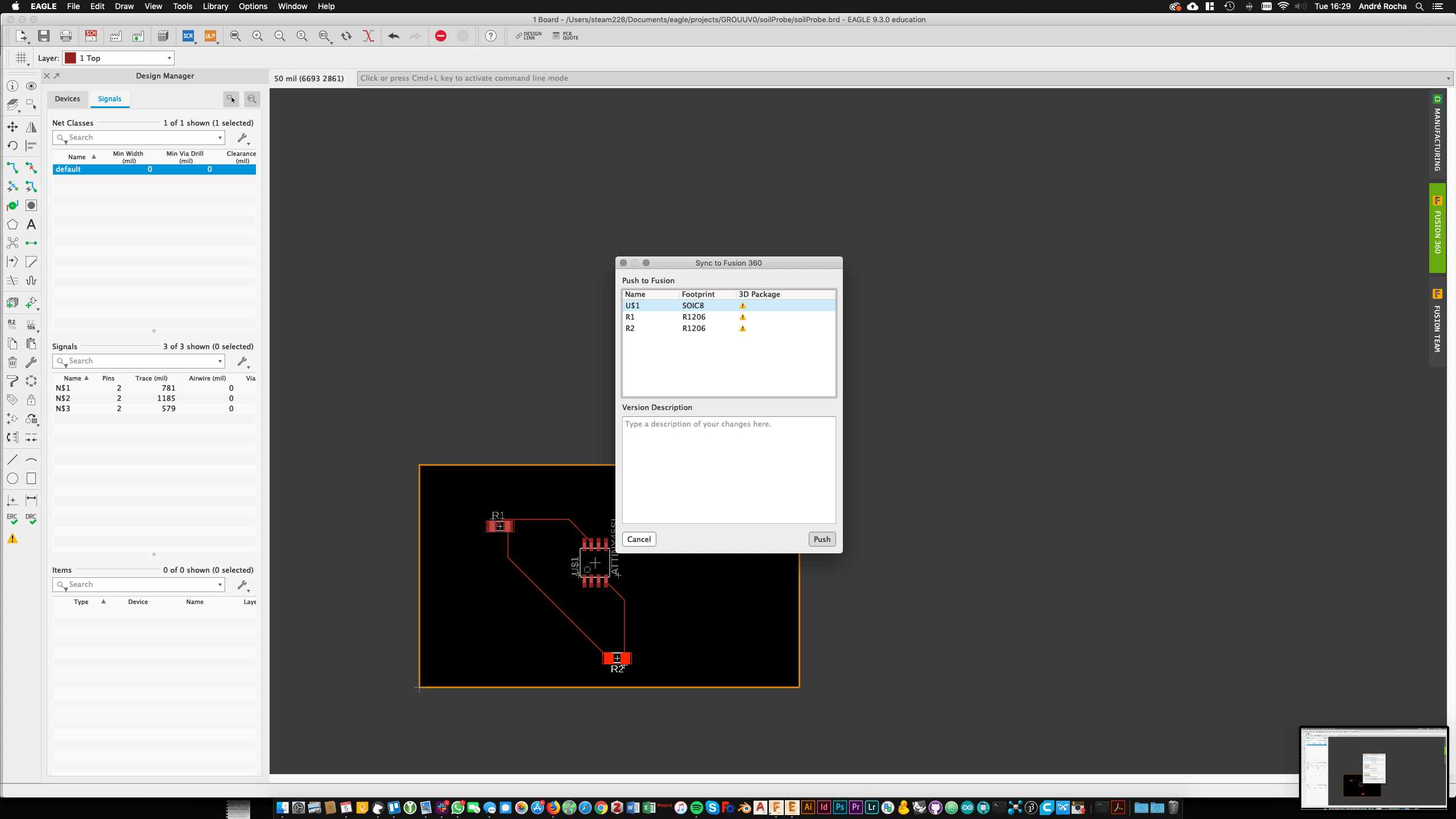
5. Pushed it to fusion but noticed that these fab library components don’t have a 3D Package (need to find if anyone already redone it like that)
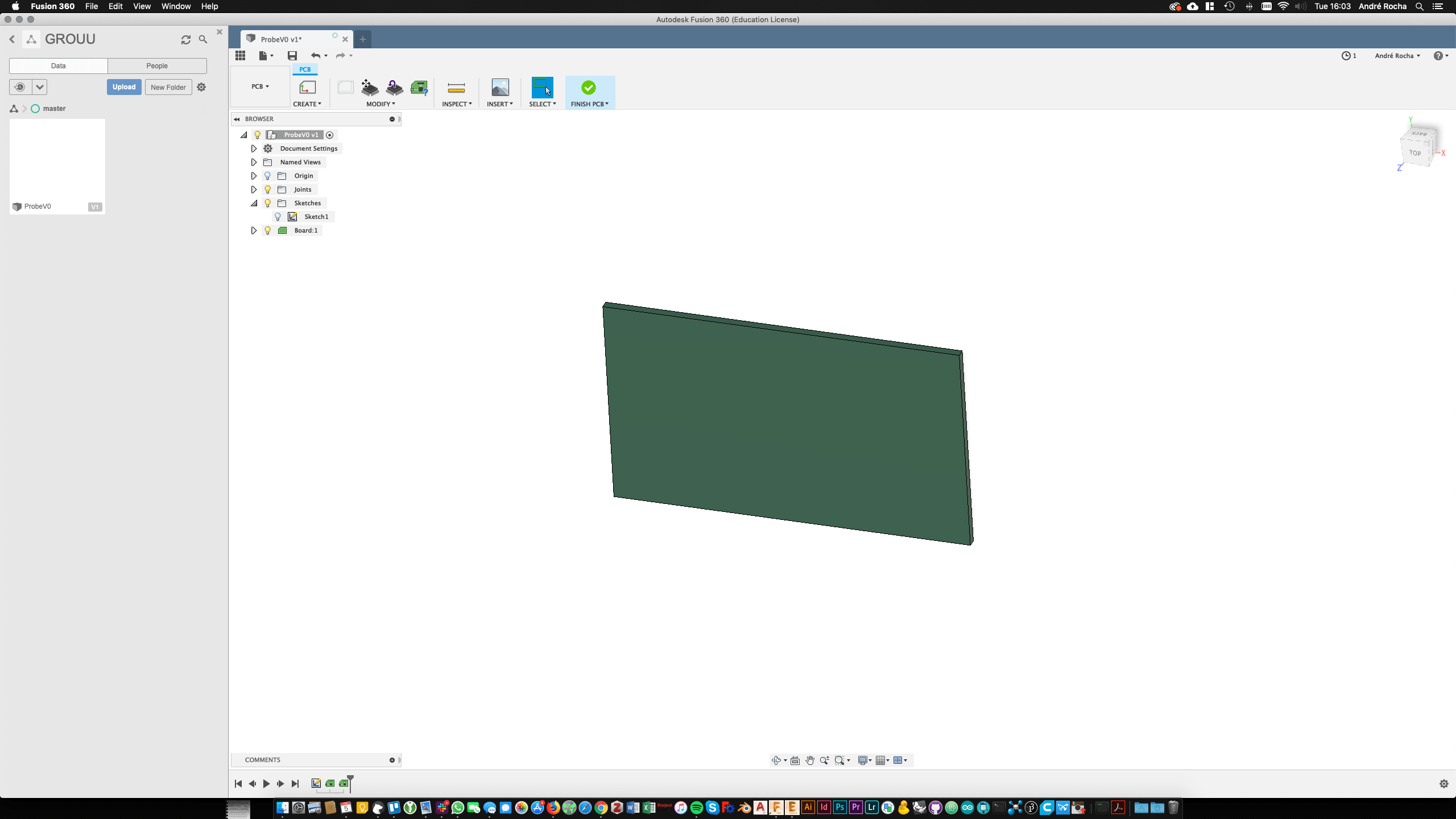
6. Again in Fusion made another random shape to alter the board. There I noticed that I couldn’t just extrude cut (which makes sense) but I could redefine the sketch that originated the board.
(note to self: will use some board 2d designs for the 2D section)
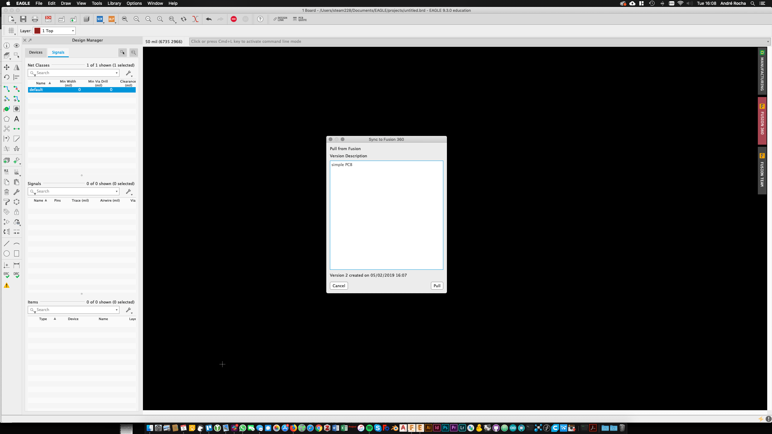
7. After saving it on fusion I was able to push this version to Eagle and voilá:
Having the basic Workflow figured out I now proceeded to the inclusion of the Eagle Project on a git Repo, so I can use it across different computers. Another question is if the eagle-fusion push and pull has to be done on the same computer every time. The Basic experiment of pushing it again on a different machine revealed a blank board on eagle. (Even tough the file synced on Fusion. Later I added the Eagle project folder to the FabAcademy gitlab repo, in order to make it available in different machines too. This solution worked perfectly in computers where I was also logged in on Fusion360 through my Autodesk account.
in the meantime, I noticed that ...
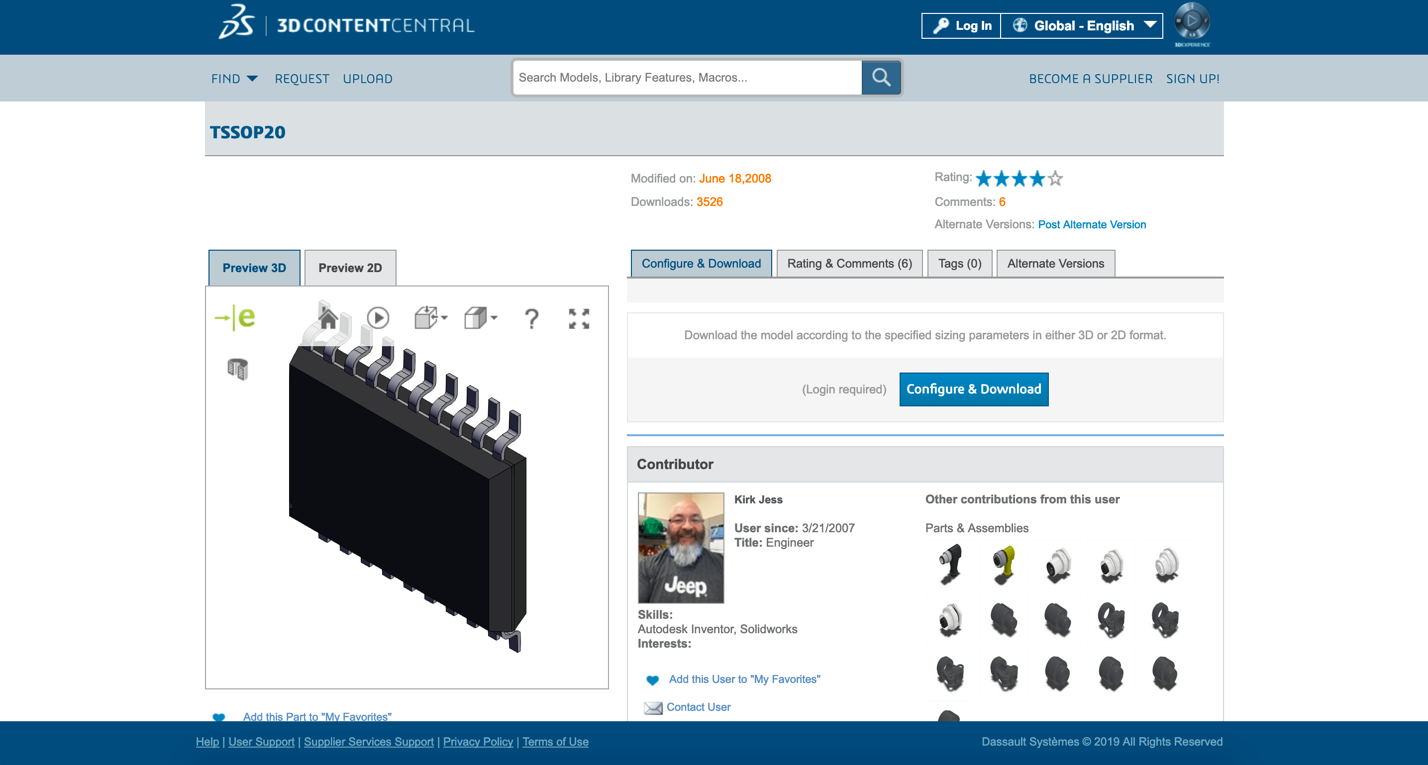
8. A second important step towards designing and making sure the integration between electronics and other physical elements works is to have a clear notion of the 3D footprint of the components and connectors on the board. 3D components are in this case essential. I then embraced the mission of translating the Fab.lbr to 3D enabled by importing it to my Autodesk Circuits.io account and adding to which component a different 3d step file. Please find the result in this link (add it, use it and correct however you wish)
How does it work?
The solution resides on the usage of STEP models that, in the case of Eagle should be uploaded and mapped on circuits.io. Then a cloud library can be created.
8.1 I uploaded Fab.lbr to circuits.io: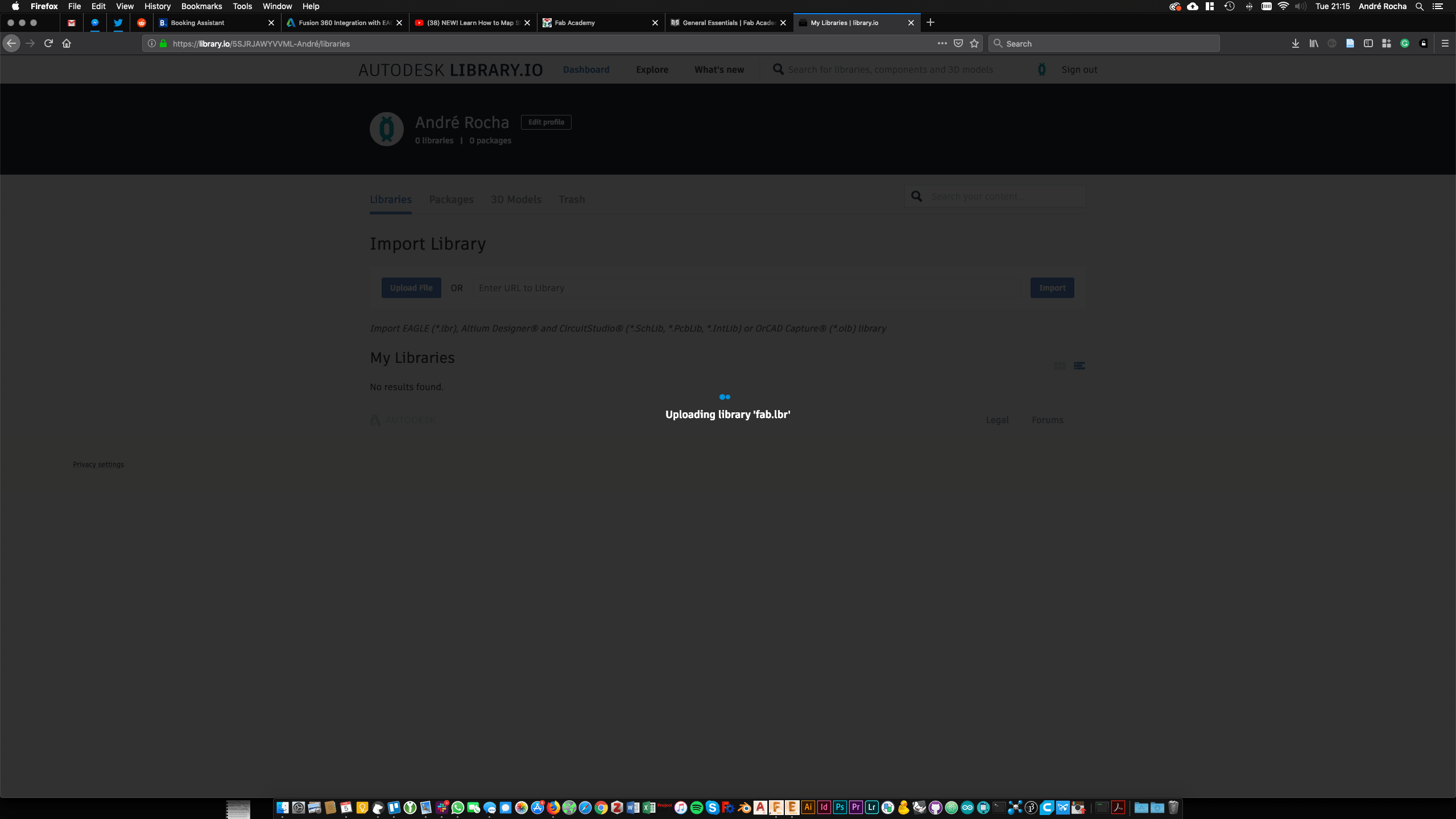
8.2 I added 3d Packages to the existing entries: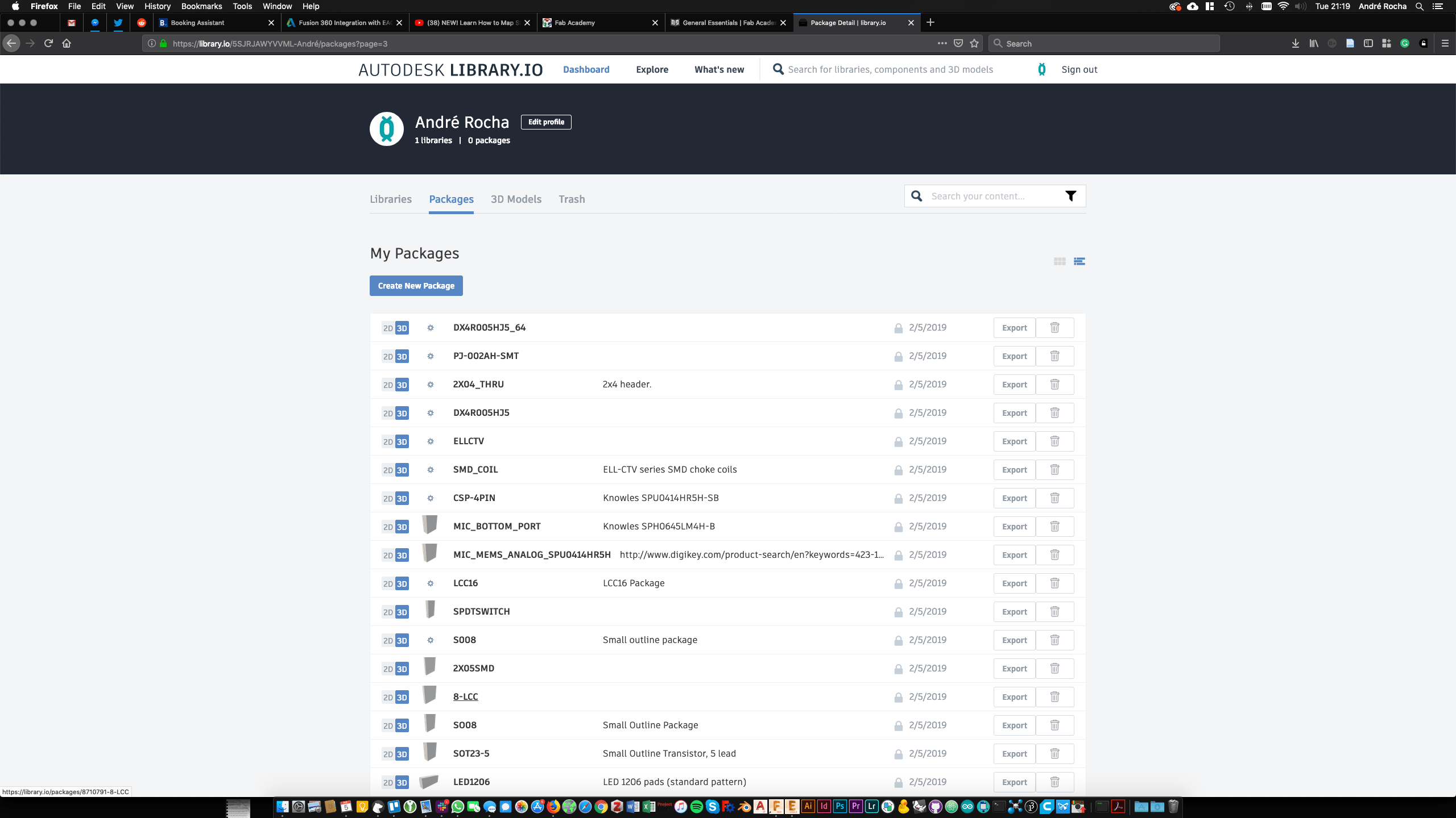
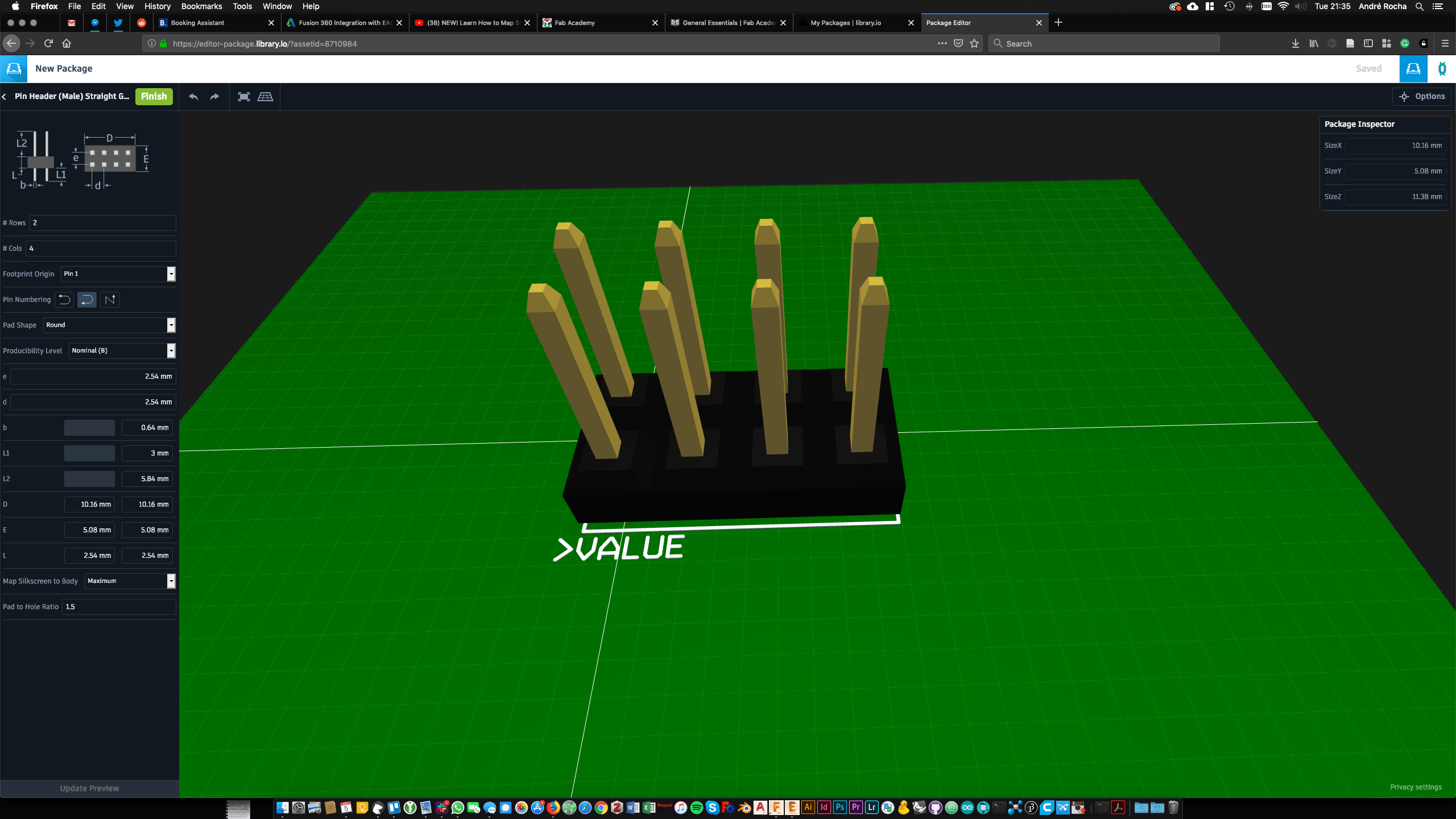
... will have to update this proces later :)