
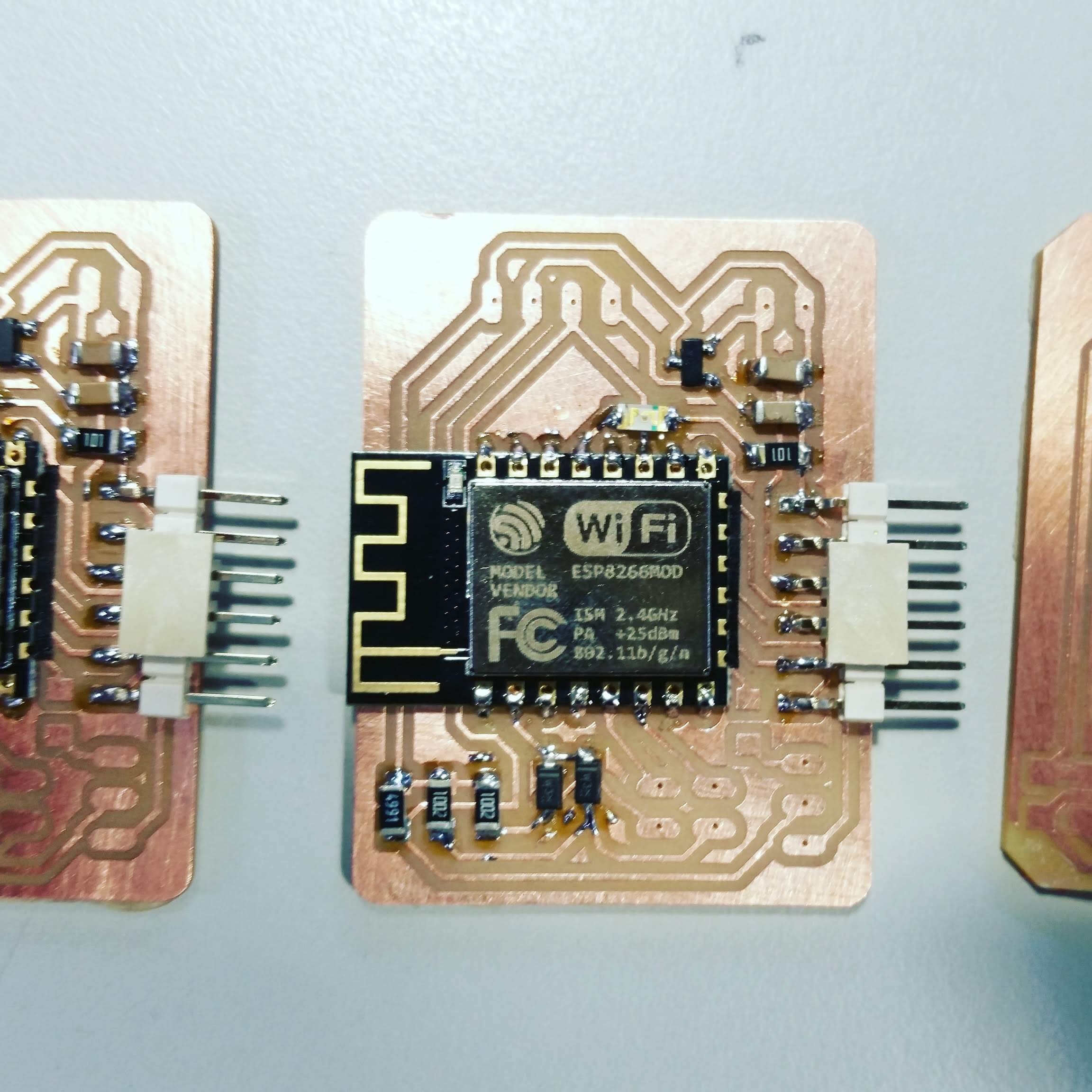
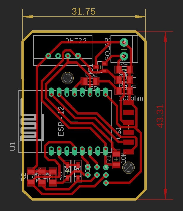
This was my first approach to designing a ESP8266 based board and it didn't go well.
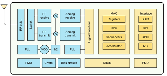 ESP8266EX Block Diagram from the Espressif ESP8266EX datasheet
After digging into this MCU datasheet, I noticed a few characteristics that could influence my approach to the code.

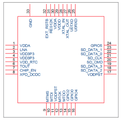
The primary conditioning was the existence of just one ADC port. "ESP8266EX is embedded with a 10-bit precision SARADC. Currently, TOUT (Pin6) is defined as ADC interface"
As you'll be able to read in the code further bellow, The strategy to implement two simultaneous Analog sensors is to connect them both to the same door and fed input voltage on both through alternating digital doors in OUTPUT mode.
digitalWrite(enableSur,LOW);
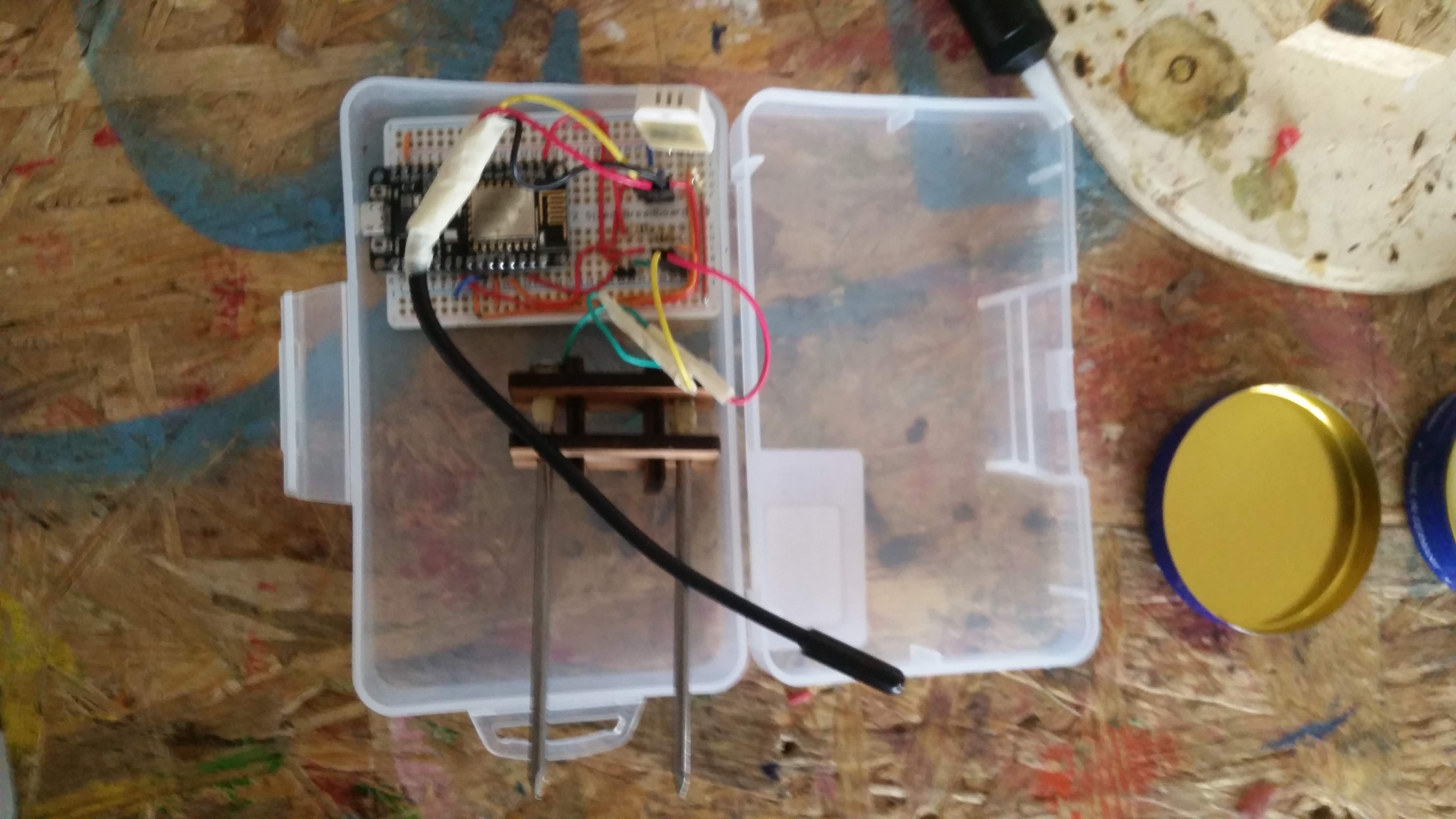
digitalWrite(enableDeep,LOW);When designing my board, I missed the auto-reset circuit. Nevertheless I completed and tested my code in a generic NodeMCU development board, which as the most approximate configuration to what I want here.
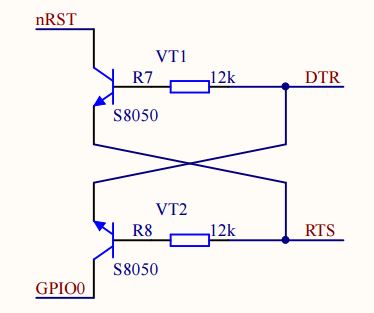 the circuit I ended up missing is essential as explained in this scheme I took from here.
Since I abandoned this component in the final project moving to the nursery side, I didn't have the time to come back to this. I will do once the course is completed, as a part of further GROUU development.
The goal of this board is to act as a sensor board for areas with Wi-Fi coverage.
 the sensor board embedded code was injected here
          /**
 * Irrigation Soil Main Probe Firmware for Wifi version of GROUU
 * Based on BHonofre, from Bruno Horta
 * to connect to NODE-RED flow ______
 *
 * unlicensed with no rights reserved by GROUU 2018 (steam228)
 *
 * */
//MQTT
#include
//ESP
#include
//Wi-Fi Manager library
#include
#include
#include //https://github.com/tzapu/WiFiManager
//OTA
#include
#include

#define AP_TIMEOUT 180
#define SERIAL_BAUDRATE 115200

//Other Libs
#include
#include
#include
#include
#include
#include


//PORTS and Global Variables

//moist
#define moistPort A0
#define enableSur 14 //GPIO14 to feed surface Moist sensor
#define enableDeep 12 //GPIO12 to feed deep Moist sensor

//soilTemperature

#define ONE_WIRE_BUS 4 //GPIO4
OneWire oneWire(ONE_WIRE_BUS);
DallasTemperature DS18B20(&oneWire);

//enviromnental - DHT22
float temp;
float stemp;
float humid;
#define DHTPIN            2
#define DHTTYPE           DHT22     // DHT 22 (AM2302)
DHT_Unified dht(DHTPIN, DHTTYPE);

Timing mytimer;
uint32_t delayMS;


//configure MQTT server
#define MQTT_BROKER_IP "192.168.1.66"
#define MQTT_BROKER_PORT 1883
#define MQTT_AUTH true
#define MQTT_USERNAME "grouu"
#define MQTT_PASSWORD "youpasswordhere"

//free MQTT brokers: https://github.com/mqtt/mqtt.github.io/wiki/public_brokers

#define PAYLOAD_ON "ON"
#define PAYLOAD_OFF "OFF"

//CONSTANTS
//ID of the Board
const String Instalation = "Habibi"; //Where is it?
const String IDCODE = "1"; //number your probe
const String TYPE = "SoilProbe"; //choose type
const String Host = "Grouu" + Instalation + TYPE + IDCODE; //just change if it is not grouu
const char * OTA_PASSWORD  = "youpasswordhere";
const String MQTT_LOG = "system/log";
const String MQTT_SYSTEM_CONTROL_TOPIC = "system/set/"+Host;
//sensors
const String MQTT_WATER_humid_PUBLISH_TOPIC = Host + "/sensor/humid";
const String MQTT_WATER_temp_PUBLISH_TOPIC = Host + "/sensor/temp";
const String MQTT_WATER_moistSur_PUBLISH_TOPIC = Host + "/sensor/moistSur";
const String MQTT_WATER_moistDeep_PUBLISH_TOPIC = Host + "/sensor/moistDeep";
const String MQTT_WATER_soilTemp_PUBLISH_TOPIC = Host + "/sensor/stemp";

WiFiClient wclient;
PubSubClient client(MQTT_BROKER_IP,MQTT_BROKER_PORT,wclient);

//CONTROL FLAGS
bool OTA = false;
bool OTABegin = false;
bool lastButtonState = false;


void setup() {

  Serial.begin(SERIAL_BAUDRATE);
  WiFiManager wifiManager;
  //reset saved settings
  //wifiManager.resetSettings();
  /*timeout relates to the maximum time before the portal to become innactive*/
  wifiManager.setTimeout(AP_TIMEOUT);

  if(!wifiManager.autoConnect(Host.c_str())) {
    Serial.println("failed to connect and hit timeout");
    delay(3000);
    ESP.restart();
    delay(5000);
  }
  client.setCallback(callback);

  dht.begin();
  sensor_t sensor;
  dht.temperature().getSensor(&sensor);
  dht.humidity().getSensor(&sensor);
  delayMS = sensor.min_delay / 1000;

  pinMode(enableSur,OUTPUT);
  pinMode(enableDeep,OUTPUT);

  digitalWrite(enableSur,LOW);
  digitalWrite(enableDeep,LOW);

  mytimer.begin(0);

}


//Chamada de recepção de mensagem
void callback(char* topic, byte* payload, unsigned int length) {
  String payloadStr = "";
  for (int i=0; i
Concluding, I would much like to develop this further, especially to take advantage of the very low
power consumption through the usage of the sleep modes, and to redesign the board for several applications.