4. Computer controlled cutting
February, 6

Assignments
group assignment: characterize your lasercutter’s focus, power, speed, rate, kerf, and joint clearance.
individual assignment: cut something on the vinylcutter design, lasercut, and document a parametric press-fit construction kit, accounting for the lasercutter kerf, which can be assembled in multiple ways, and for extra credit include elements that aren’t flat.
Conclusion
We characterize the laser kerf: 0,1 to 0,2 mm, the later is a very tight situation. We practice the focus, review the security issues, discuss the use of the power, speed, rate and join clearance for several materials: acrylic, MDF and cardboard.
For the individual work, I use the vinyl cutter to make a stick and the laser cutter to make a ARDUINO PHYSICS box. This is a project we are developing at Lab Aberto Fab Lab, were we use Arduino to make measurements, calibration, correlations, etc. The ARDUINO Physics box its an old project that will gain with this box organization, since this is a project need to be organized in boxes in order to be delivered when in action with the students/learners, we I want to do this box to organize it to be used in the classroom or at any lab. This project will be furthr developed after October 2019.
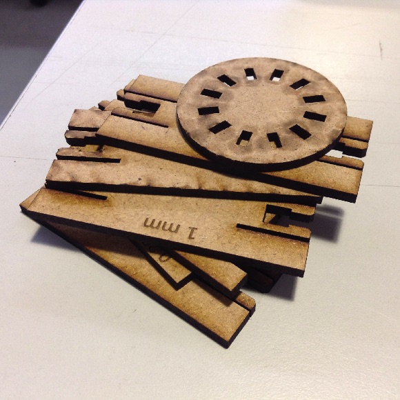
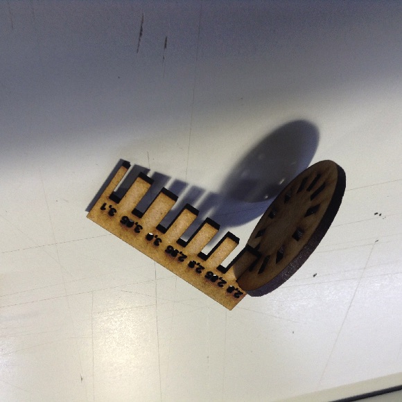
I tryed to do a GIK in order to test press-fit and the kerf. I also made several long “arms” to test the resisteance and the flexibility of the MDF. I also, test the bending of Aaron Porterfield.
I documented the code used for the parametric box design that use the machine kerf to make the ARDUINO Physics box complete with OPENSCAD.
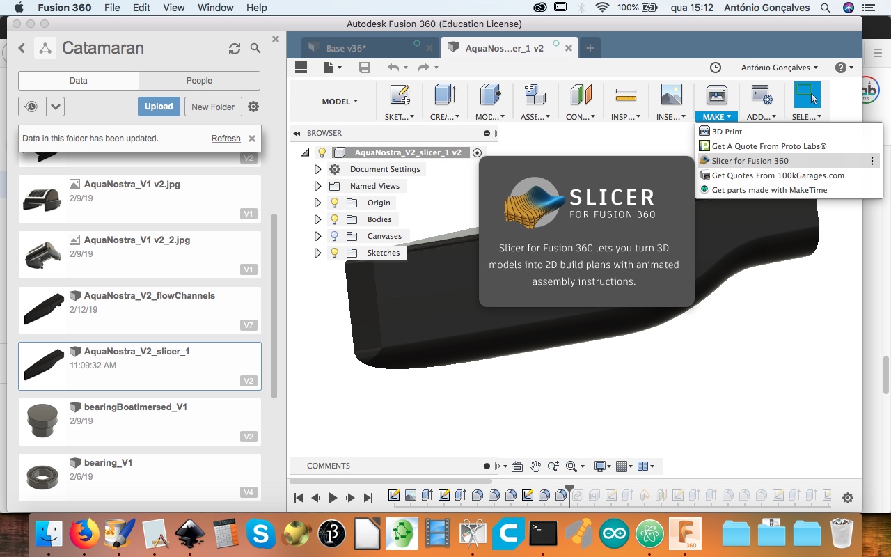
I also use this week SLICER from FUSION360 for the boat hull and cut it to see the the details and discuss the next developments.
I found usefull the use of another 2D cad, QCAD, very usefull for DXF and SVG files.
I think its best to use FREECAD in this case or FUSION360, instead of INKSCAPE, to make objects with a lot of symetries and so many constraits. Its more user friendly. BUT, its not impossible to use INKSCAPE, it just take a few more steps which I documented. With practice it turns out ok.
I discuss and found the distinction between copying and clonning: ALT + D to clone. The MIRROR extension its problematic but possible to use. For the parametric issue I didn’t found an extension to be used on INKSCAPE.
Todo
- Repeat the ARDUINO Physics box cutting
- Complete the bending cutting
- Cut the stick
- Markdown code integration
- Cut the lattice diagram
- Make the vinyl cutter procedure (p.65 of the log book)
- Comment the bending cutting
- Vinyl cutter image
- Box pic
- Video showing the flexibility of MDF
- Repeat the cutting tests using cardboard
- Cut the slice for the boat with cardboard
- Update the connection with the vinyl cutter for MAC (xcode and inkcut)
- Make a board to test each material in the laser cutter
Work done
Security
Procedure
At this Fab Lab we used CORELDRAW to print to the machine.
Step 0: verify the physical cable conections Step 1: after you done the design, turn the exhausts on; Step 2: focus the laser (follow the specific procedure to your machine: press the focus button; jog the upper or down button to controll the distance between the laser head and the material with the specific tool provide at the machine; push the foward button to get to the working position) Step 3: if the machine didn’t work before, run a small cut without the material to heat it first Step 4: before cutting your design, just draw a square and cut it to see if your parameters are ok for your material
discuss those parameters with the senior staff if your machine as raster, follow the local procedure to use color mapping
Step 5: Rearrange the parameters Step 6: send the file to the machine Step 7: choose the file on the screen of the machine and press GO
DON’T LEAVE THE MACHINE ALONE!
Step 8: after the machining is done, wait for a fez seconds before you open the window of the machine (in order to exhausts are completed) Step 9: remove your drawing and clean the bed of the machine. Step 10: shut all the systems down
Laser cutter parameters
We use this parameters, according to the machine manual. For the MDF I use this paramenters:
Power: 100 % Speed: 12 % Frequency: 500 Hz Material max dimensions: 600 x 300 mmm
Inkscape
Integrating INNKSCAPE with other tools like COREL or ILUSTRATOR it seems not straightforward. Sharing SVG and DXF sometimes goes wrong. What seems t work better is PDF.
Don’ts
- Don’t use CTRL + C to copy objects, they won’t be paths that can be used in BOLEAN operations
Do’s
- Use CTRL + D to duplicate the object
- Use ALT + D if you want to CLONE the object: if you change one the other will change
- Watch this video to start: https://www.youtube.com/watch?v=A1FIl5Eq4PQ
- Watch this video on how to use extensions (box maker extension): https://www.youtube.com/watch?v=A1FIl5Eq4PQ
- Use PDF to export for other sftware tools
- I found QCAD very usefull to wirk with DXF and convert them to SVG, whenever INKSCAPE have same issues
Mirror
- Install extensions: https://www.youtube.com/watch?v=StNTZ1xeW0o
- List of xtensions: http://wiki.inkscape.org/wiki/index.php/Extension_repository
- Inkscape keys list: https://inkscape.org/da/doc/keys045.html
- Inkscape tutorials: https://forum.inkscapecommunity.com/index.php
Mirror Extension
The MIRROR extension its crippy to be used. Follow this steps:
-
- Install de MIRROR extension (see video above).
-
- Reopen INKSCAPE.
-
- This MIRROR extension its hidden in the “modify path” menu.
-
- draw a line: it will be mirror axis.
-
- draw the object to be mirrored.
-
- Select the Object and group it and CTRL + D to duplicate (or ALT + D to clone).
-
- Choose the OBJECT and SHIFT + RIGHT CLICK on the AXIS.
-
- Choose in the menu EXTENSIONS > Modify Path > MIRROR.
-
- Wait a few seconds.
-
- If you choose clone, all the changes in one objects will be done also on the other.
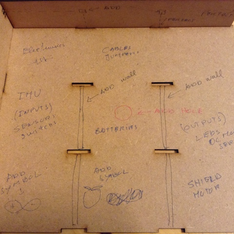
ARDUINO Physics box
BOX for the ARDUINO PHYSICS project (does it clip?)

3D simple “GIK” (does it clip?), I found good ideas for junction with a former Fab Academy student Thomas Feminier and Sigridur Helga.


About GRASSHOPPER, I thought about using it, it cames with RHINO 6, but for Mac, its only available for 90 days. So I decided do use openscad. During this section with Neil, I found the junction he showed very interesting and try to do it with Openscad, with parametric customization.
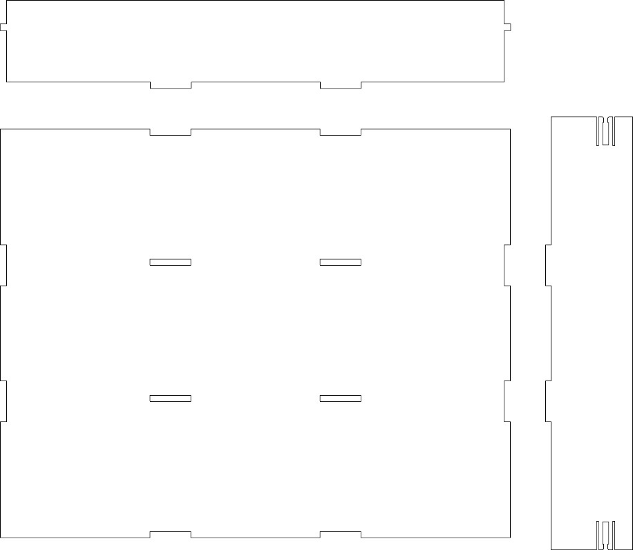
/*ARDUINO Physics, the goal is to make a box for 5 groups of participants to learn about inputs and outputs sensors and actuators on projects about Physics with Arduino
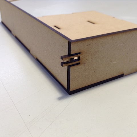
Features: pressfit with tfc of space for the flexibility channel
The kerf is not at the reentrances on the base, but on the joints at the walls
There are two smallest walls because they differ by the tickness, T
This design only show one piece of each waal necessary. The repeated waals can be done when using the software to cut at the laser
*/
//Parameters============
//box variables, all in milimetters (mm)
L=230; //lenght, X axis
W=200; //width, Y axis
H = 40;//height
//machine settings
K = 0.2;//decide about the kerf of your laser machine: FCT FAB LAB machine kerf range 0.2 to 0.1
//material settings
T = 3;//thickness of the material to cut
d = 40;//distance between the parts on the XY axis
//joints
jl = 20;//joint lenght
nojb = 3;//X axis, number of joints on the bigger side of the base
nojs = 2;//Y axis, number of joints on the shorter side of the base
tfc = 1;//thickness of the flexible channel
lirpf = 8; //lenght of the interior rectangle of the press fit
//base===================
difference(){
//box base in 2D
square([L,W],true);//base
//joints on the base
for(i=[1,-1])for(j=[-3/2,-1/2,1/2,3/2])for(k=[1]){
translate([i*L/6,j*W/3+k*T/2,0])square([jl,T],true);//joints on the base for the interior and exterior walls;
}
for(i=[1,-1]){
translate([i*L/6,3/2*W/3-T/2,0])square([jl,T],true);
}
//#translate([0,W/2-T/2,0])square([jl,T],true);
for(j=[1,-1])for(i=[1,-1]){
translate([i*L/2-T/2,j*W/6,0])rotate(90)square([jl,T],true);
translate([i*L/2+T/2,j*W/6,0])rotate(90)square([jl,T],true);
}
}//box base end
//waals=====================
union(){//biggest wall, X AXIS
translate([0,W/2+T+d,0])square([L-2*T,H],true);
for(i=[1,-1])
translate([i*L/6+K,W/2+d-H/2+T/2,0])square([jl+K,T],true);//double joints, kerf included
translate([L/2-T/2,W/2+d+H/6+T,0])square([T+K,T+K],true);//vertical joints
mirror()translate([L/2-T/2,W/2+d+H/6+T,0])square([T+K,T+K],true);//vertical joints, for the press fit of the smallest wall (Y AXIS, kerf included
}
difference(){
union(){//smallest wall, Y AXIS
translate([L/2+d,0,0])square([H,W+2*T],true);//smaller wall
for(i=[1,-1])translate([L/2+d-H/2-T/2+K,i*W/6,0])rotate(90)square([jl+K,T],true);//double joints, kerf included
}
a=2*H/3-3*T/2-tfc;//local variables, heigh of the bigest rectangle to remove from the press fit
//lirpf=8; //lenght of the interior rectangle of the press fit (REPEATED above)
b=H/3-3*T/2-tfc;//lenght of the upper removable rectangle
union(){translate([L/2+d+H/6,W/2+T/4-3*T/2,0])square([T,lirpf],true);//interior rectangle with lirpf mm, with press fit 1 mm (0.5+0.5)
translate([L/2+d+H/6,W/2+T-T/2,0])polygon([[T/2-0.5,T/2-0.5],[T/2+0.5,T/2+0.5],[-T/2-0.5,T/2+0.5],[-T/2+0.5,T/2-0.5],[-T/2+0.5,-T/2],[T/2-0.5,-T/2]],1); //press fit square with the chanfer
translate([L/2+d+H/6-3*T/2-tfc/2,W/2-lirpf/2+T/2,0])square([tfc,lirpf+T],true);//flexible rectangle, very important the position, because it will define the tickness of the press fit arms
translate([L/2+d+H/6+3*T/2+tfc/2,W/2-lirpf/2+T/2,0])square([tfc,lirpf+T],true);// upper flexible rectangle, very important the position, because it will define the tickness of the press fit arms
//removable rectangles, upper and down
translate([L/2+d+H/6-(3/2*T+tfc+a/2),W/2+T/2,0])rotate(90)square([T,a],true);//downward rectangle, removed parts near the press fit
translate([L/2+d+H/6+3*T/2+tfc+b/2,W/2+T/2,0])rotate(90)square([T,b],true);//upper rectangle, removed parts near the press fit
}
mirror([0,1,0])union(){translate([L/2+d+H/6,W/2+T/4-3*T/2,0])square([T,lirpf],true);//interior rectangle with lirpf mm, with press fit 1 mm (0.5+0.5)
translate([L/2+d+H/6,W/2+T-T/2,0])polygon([[T/2-0.5,T/2-0.5],[T/2+0.5,T/2+0.5],[-T/2-0.5,T/2+0.5],[-T/2+0.5,T/2-0.5],[-T/2+0.5,-T/2],[T/2-0.5,-T/2]],1); //press fit square with the chanfer
translate([L/2+d+H/6-3*T/2-tfc/2,W/2-lirpf/2+T/2,0])square([tfc,lirpf+T],true);//flexible rectangle, very important the position, because it will define the tickness of the press fit arms
translate([L/2+d+H/6+3*T/2+tfc/2,W/2-lirpf/2+T/2,0])square([tfc,lirpf+T],true);// upper flexible rectangle, very important the position, because it will define the tickness of the press fit arms
//removable rectangles, upper and down
translate([L/2+d+H/6-(3/2*T+tfc+a/2),W/2+T/2,0])rotate(90)square([T,a],true);//downward rectangle, removed parts near the press fit
translate([L/2+d+H/6+3*T/2+tfc+b/2,W/2+T/2,0])rotate(90)square([T,b],true);//upper rectangle, removed parts near the press fit
}
//small joints for the interior waals
translate([L/2+d+H/6,W/6,0])square([T,T],true);
translate([L/2+d+H/6,-W/6,0])square([T,T],true);
}
//interior wall, X AXIS, with two small squared joints without the kerf, sparated by d plus H/2
translate([0,d+H/2,0])difference(){union(){//biggest wall, X AXIS
translate([0,W/2+T+d,0])square([L-2*T,H],true);
for(i=[1,-1])
translate([i*L/6+K,W/2+d-H/2+T/2,0])square([jl+K,T],true);//double joints, kerf included
translate([L/2-T/2,W/2+d+H/6+T,0])square([T+K,T+K],true);//vertical joints
mirror()translate([L/2-T/2,W/2+d+H/6+T,0])square([T+K,T+K],true);//vertical joints, for the press fit of the smallest wall (Y AXIS), kerf included
}
//small joints for the interior waals, X AXIS
translate([L/6,W/2+d+H/6+T,0])square([T,T],true);
translate([-L/6,W/2+d+H/6+T,0])square([T,T],true);
}
//smaler interior wall. They differ by T
translate([0,W/2+4*d,0])union(){
translate([0,W/3,0])square([W/3-2*T,H],true);
translate([(W/3-T)/2,W/3+H/6,0])square([T+K,T+K],true);//vertical joints with the kerf
translate([-(W/3-T)/2,W/3+H/6,0])square([T+K,T+K],true);//vertical joints with the kerf
translate([0,T/2,0])square([W/3-T,H],true);
#translate([(W/3-T)/2+T/2,-(W/3+H/6-2*d),0])square([T+K,T+K],true);//vertical joints with the kerf
#translate([-(W/3-T)/2-T/2,-(W/3+H/6-2*d),0])square([T+K,T+K],true);//vertical joints with the kerf
}
Bending
On the web I found Aaron Porterfield, with very interesting bendings built with a laser cutter.
(to be updated)
walls flexibility
How thin can be a wall made by a laser cutter? And what is the resistance and flexibility?
(to be updated)
Results
The ARDUINO PHYSICS box didn’t work very well, same issues about the kerf, I need to do it again. I need to it evaluated better.
Another try with the ARDUINO Physics box, the evaluation and future updates:
Evaluate the press fit of the ARDUINO Physics box:
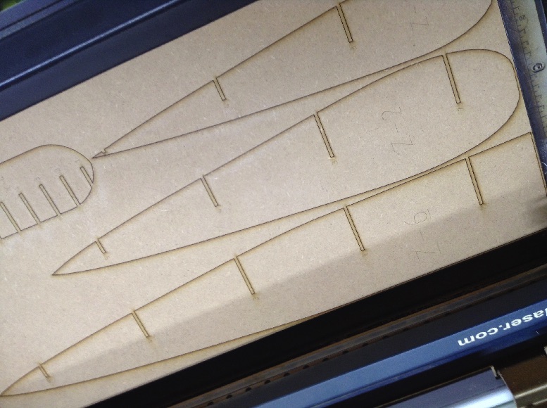
Boat slice
I started the boat cutting using the FUSION360 slicer tool. Open it.
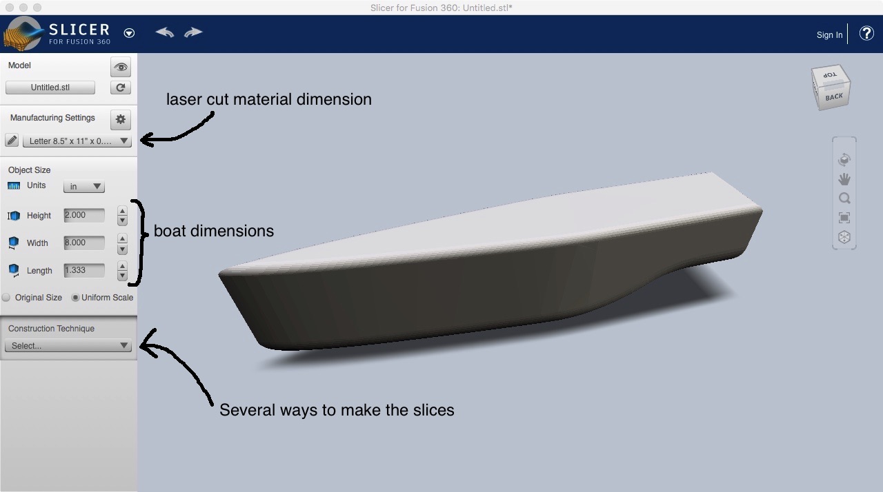
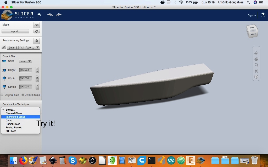
then choose: Material dimensions; object dimensions; type of constructions: choose and see what they do.
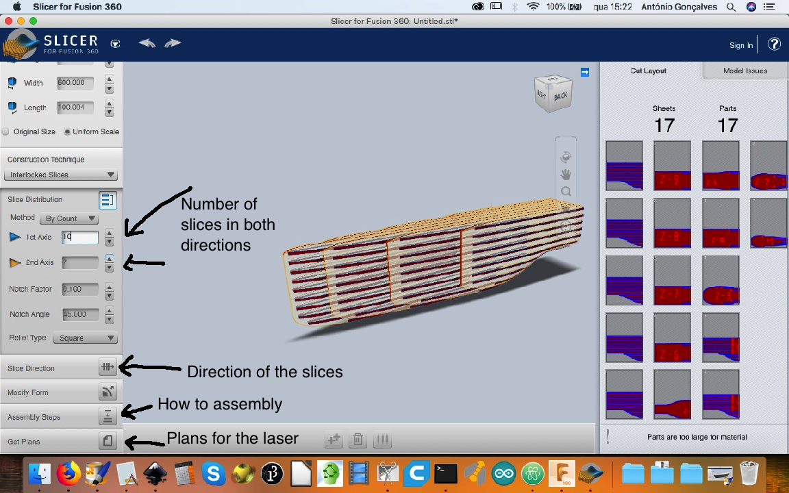
I choose: “Interlocked Slices”
You can choose the number of slices in Y or X diretions; you also can see how to assemble it and get the plans to cut on the laser. If you push the “Slice Direction” button on the bottom left, you can change the three directions.
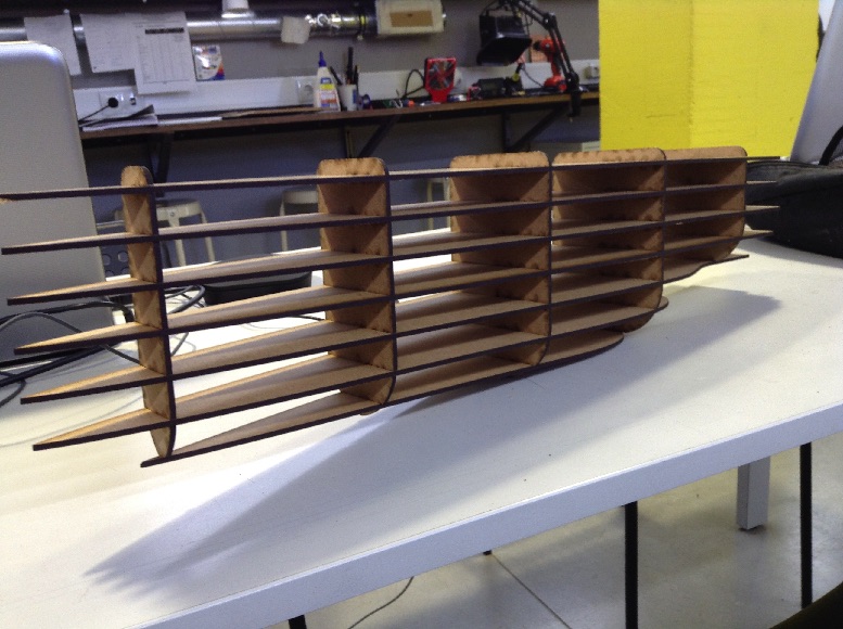
This are the results:
Cutting!
Assemble it!
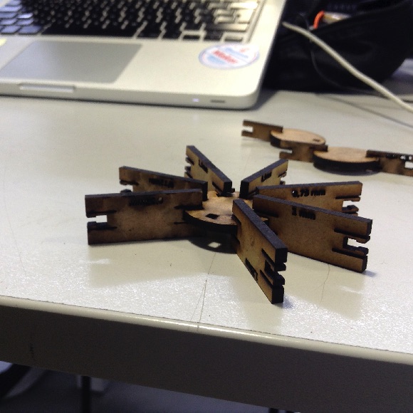
GIK
 ]
]
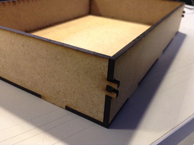
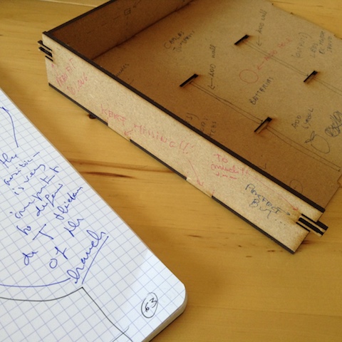
ARDUINO Physics box result:
Continue testing… getting there. At this moment this box needs a little more adjustments but it has been used already.
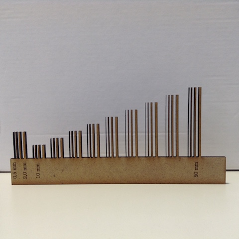
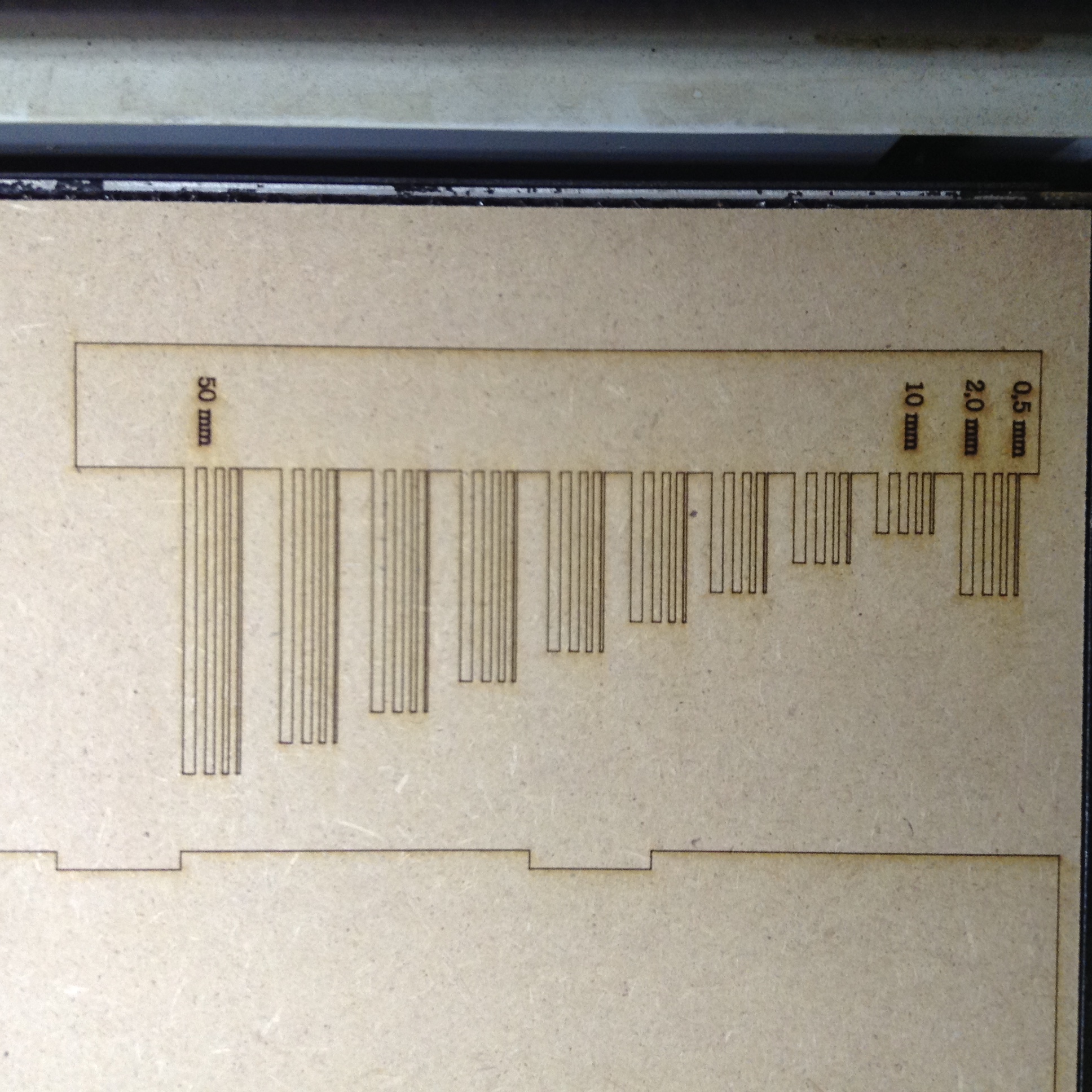
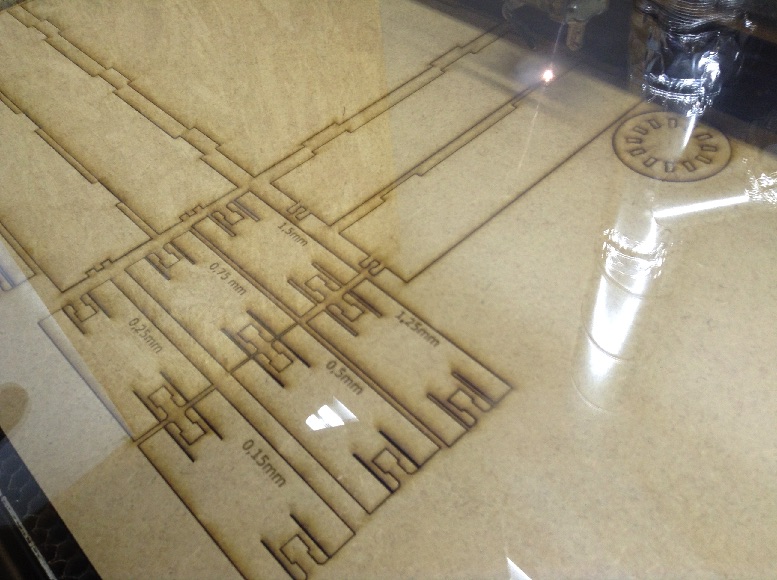
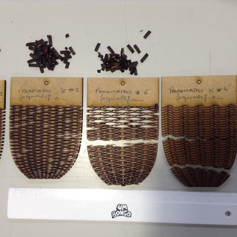
Walls
Kerf seems to range from 0.1 mm to 0.2 mm (really tight)
Kerf evaluation
For this machine I found the kerf value for the walls to be tight with each other in a range of values between 0,1 mm to 0,2 mm, where 0,2 is really tight.
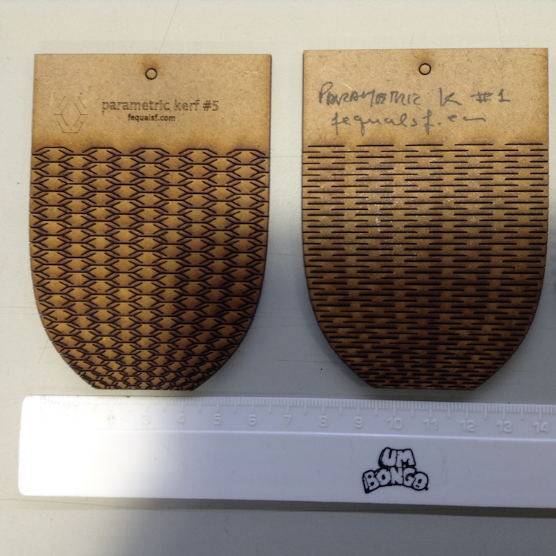
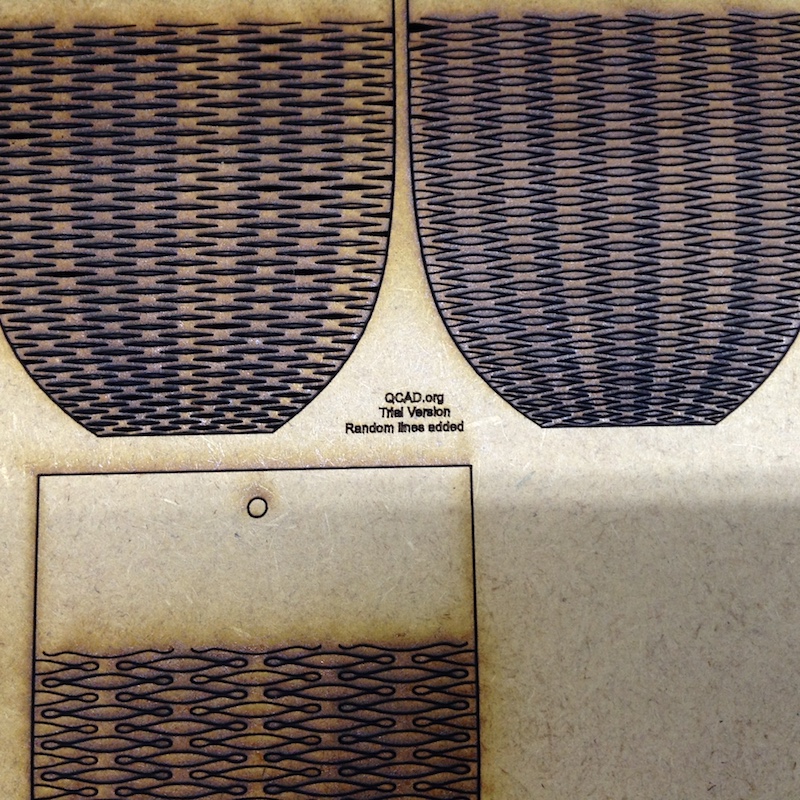
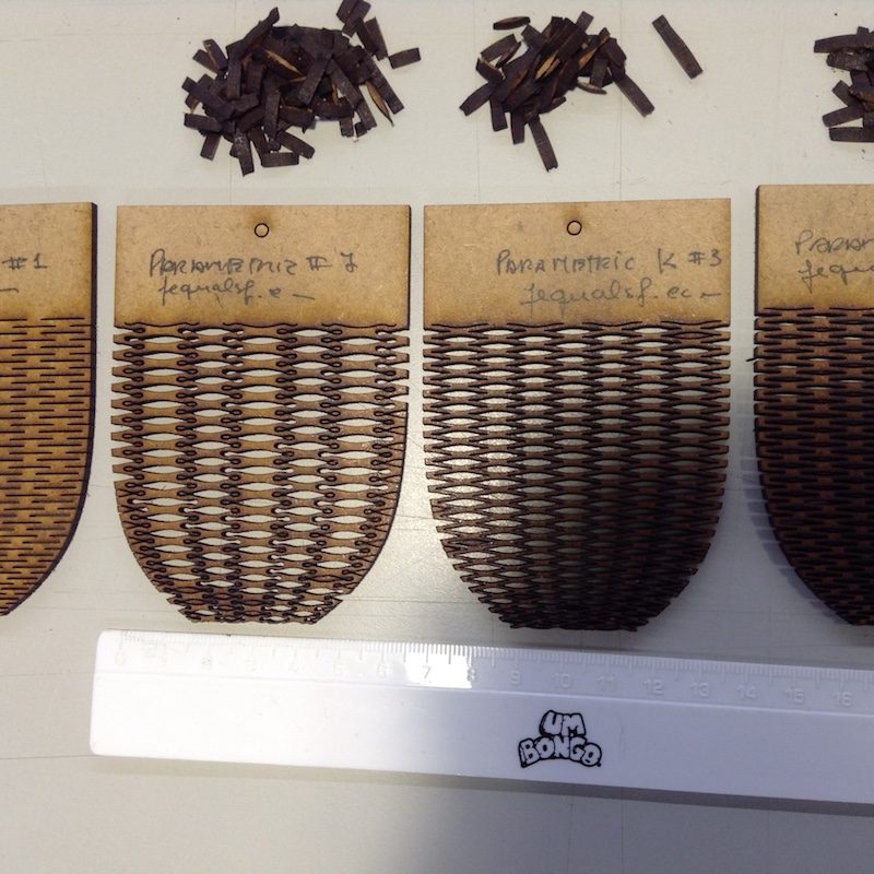
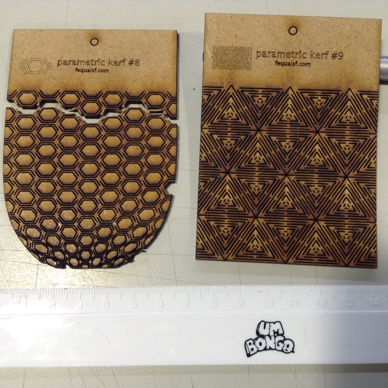
Bending results
The parametric kerf #1 was the best that I found: simple design and very flexible. The #5 and #9 was also very good. The others broke after several experiments of bending them. Perhaps if I cut them larger they could be best.

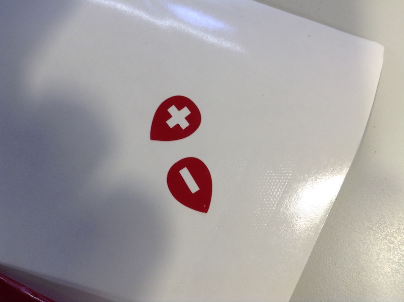
vinyl Cutter
After several attemps I could connect the MAC with the Vunyl cutter (I will try it later and update this document for MAC)
After using Inkscape to draw and convert the objects to vector, I choose in the menu: extensions → export → plot. It opens a window with several settings: verify the port and click on apply. This are the results just after the cutting:
One of the staff membrers, Adrian, help me to transfer the former cutting to the box using the same sheet were we cut the signs since we don’t have the proper transfer film. Wonderfull!
We get this result:
I use this settings on the machine: speed 100 mm/s ad Force 60 g. Before this there is a need to:
- Calibrate: align 7 cm from the right; Set the zero;
- Click on offline/pause;
- Push downward the press button to secure the sheet;
- At Inkscape, choose extensions -> export -> Plot
Note
Don’t change the basic values; choose the wright serial port;
-