11. Input devices
assignments for this week
- Individual: measure something: add a sensor to a microcontroller board that you have designed and read it.
- group assignment: probe an input device’s analog levels and digital signals.
Fab Academy Inputs Week11 from António on Vimeo.
Summary
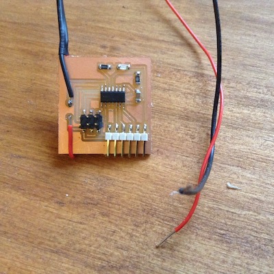
This time I did want to start doing sommething more close to the electronics final job for the unmanned boat, directly related to the boat security as shown in the video. So I decided, after discussing it with the tutors to find interesting to develop a very simple PCB with a conductivity wire switch.
One of the challenges was to do the PCB* autonomously, and I did it, feeling more confortable with this type of task for the next upcoming weeks.
Restarting to reviewing the Eagle procedure, solving same minor issues that were not very well understood. One of the major issues in this part was managing the reference (0,0,0) with the XCARVE when doing the cutout. Next time I will be aware of this step.
I also manage, with the help of Luis Carvão, to solve the issue that goes back to week 5: complete the toolchain with arduino IDE. They were directly related to: - Computer Permissions; - Serial library: the ATtiny’s doesn’t use UART but USI (Universal Serial Interface), so there is a need to define the serial name and to define the TX, and RX pins; - RX, TX pins: they need to be interchange to the pins at the hardware (see code bellow and the PCB circuit); - The problem ot the weird characters at the serial terminal were solved using the USI serial code; - IN the next board I will include a RESET button;
With this search I really dig into the terminal code of MAC and LINUX. Very interesting but very hard.
I also search about ways to reduce the SRAM use of ATtiny because it happens to get full very quickly. I learn to use the FLASH memory with F() function and see that there other technics more advanced in the code side.
The code used at the ARDUINO IDE is very simple and need further developments in order to be possible to use ATtiny44.
After reviewing Neil lecture for this week I can see same interesting sensors to test, not on this week, but in the comming weeks and years. I did make the schematics based on Neil examples for the step response and did the PCB’s.
About the group assignement, I did same measures with the oscilloscope but didn’ go further nor documented it as a group in that week. Manage to complete it now.
Todo
- toolchain solved(from week 5, 7 and 9)
- Step response sensor one/two pads: must do! Start here
- group assignment
- toolchain using C language and the terminal (from week 5, 7 and 9)
- Magnetic field or Temperature sensor or accelerometer
- Light sensor (UV)
- LED as a light sensor
- Step: can it measure angles? yes!
Work done
Neil
Meil Lecture notes
There are three registers: |Register|type|What it does?| |--------|--------|------| |DDxn|direction|Do you listen or do you talk out| |PINxn|Input|Whats happening in the pin?| |PORTxn|Output|Send data out|
- I/O pins/ports: page 56 of this datasheet: it is possible to see the way INPUT_PULLUP resistor is ativated by the PUD (see p.66 of this datasheet): if this bit is 1, the INPUT_PULLUP is disabled. In detail: if the BYTE HEX 0x36 (Binary: 111001) is on the BUS, the acessed register MCU is acessed and if the bit PUD is 0, the INPUT_PULLUP is enabled;
- Diferences between PINS and PORTS: (???);
- Analog comparator (p.123): compares two voltages, saying if one is abouve or bellow the other by TRUE or FALSE output, but it can do it very quickly: voltage AIN0 > voltage pinAIN1 -> ACO sets; for the ATtiny44, the pins, PA1 (12) and PA2 (11), respectively.
- ADC (p.127) : Analog to Digital Converter: reads a voltage and converts it to a number; a multiplexer peaks which pin to read in; OPTIONS: reads the diference of two voltages and converts to a number; can amplify; there is a need for a reference voltage; it can interrupt;
- Temperature sensor (p.143, ATtiny44 similar): selecting the single-ended channel ADC4 enables the temperature sensor: ADC p.127, figure 17-1 ( ATtiny45 datasheet);
- Reference register (p.138, ATtiny45 datasheet);
- Several other register to process signal and output data slower or faster;
- Buttons and pullup resistor;
- The Oscillator Calibration Register (0x31) is used to trim the Calibrated Internal RC Oscillator to remove process variations from the oscillator frequency (p.32, ATtiny45 datasheet): Fixed frequency within: 6 – 8 MHz;
- debouncing means not reading the time that takes for the signal to came from 5V to 0V;
- IR: pyroelectric sensors: measures changes, not the “light” intensity;
- Sonar: it doesn’t work with walls that are not paralell to the sensor: trigger out and the pin board reads the eco pulse voltage back in: it uses a usefull part of the processor, the 8-bit Timer/Counter (p.67, ATtiny44 similar): it can count events and also measure time;
- Magnetic field sensor: need for ADC to convert a voltage to digital number: reads it 100 times to reduce the noise;
- Google serial standard;
- Temperature: RTD and NTC are difference, they change in opposite behavior: RTD higher temperature and NTC at lower temperature: make a bridge to detect small changes: calibrate with a table for more accuracy;
- Phototransistors: the light works as a gate source; Synchronist detection: its possible to detect movement by blinking the light source very fast;
- accelerometer: $$ I^2C $$ protocol: talking to registers; they can have also gyroscopes;
- Sound
- LED can be used as sensor lights (not very good) if you use negative voltages: current proportional to the light coming in;
- Step response: really interesting: possibilities: resistance, capacitance, inductance, position, pressure, force, tilt, acceleration, humidity, proximity, touch, multitouch,… could we measure angles? Versions: one electrode or two; for one touch pad, since R is large, small changes in C can be detected. ADC are not so fast, so measure when the wanted reading happen (Neil video, time 1h:04:28); be CAREFULL don’t use long wires between the processor and the sensor pads: you will measuring the wire as a sensor otherwise;
- Step response: liquid level for the boat.
- accelerometer: moving and fixed electrode;
- Material properties: just run it faster: documented here and also dieletric capacity measurement here.
- A sensor magnet with five magents inside to sensor a magnet position: joystick uses it.
- Image: jpeg camera and arducam;
- Image processing: PIXY and OPENMV; More power: openCV and libuvc;
- WEBRTC: put video on a webpage;
Eagle
I started to sketch a schematics at Eagle based on the work done in week 07. I didn’t remember [almost] anything!
For instance: - How to put labels? Watch this, minute 2:50. - How to manage Libraries? I had to find a bluethooth Library: see this one.
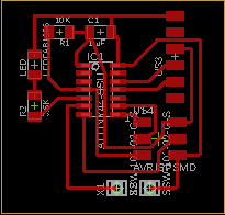
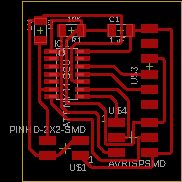
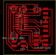
I manage to recover all by reading the week 5, 7 and 9, and found out the importance of the ongoing writing, one of the Neil educational/project strategy. The shematics, the circuit and the PCB board:
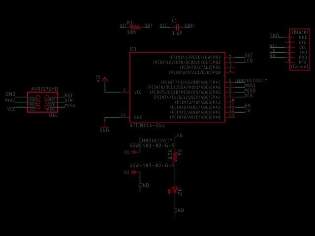
Note that the wires are connected to the pin 7 (or pin 6 in the ATtiny) and GND, while the led is at pin 8 (or pin 5 in the ATtiny). The rest is similar to the last week 9.
Note that the wires are only a kind of switch: if we put it in water it will be LOW in the pull_up.
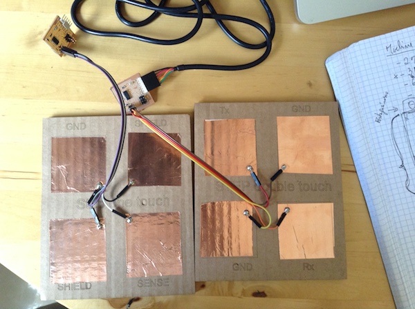
Step response: one Touch
Listen to Neil lecture video at 55:36, he introduce the step response mechanism and I was curious about it. So I manage to make the board and the cardboard and start to test it with the following arduino and processing programs:
(arduino)
/*
  read analog voltage at pin A3 in two different times (ruled by ADC pin settling time);
*/
#include <SoftwareSerial.h>
int sense, sense_0;//variables to be measure at two different moments
int settlingTime = 3; //3 ms to wait for the signal to settle: 25  ADC clock cycles, ATtiny44 datasheet p.129 and 159


SoftwareSerial Serial(1, 2); // RX, TX serial communication

void setup() {
  // initialize serial communication at 9600 bits per second:
  Serial.begin(9600);
  pinMode(A3, OUTPUT);
}

// the loop routine runs over and over again forever:
void loop() {
  digitalWrite(A3, LOW);
  delay(settlingTime);
  //Serial.println("LOW");
  sense_0 = analogRead(7);//measure initial voltage
  digitalWrite(A3, HIGH);
  delay(settlingTime);
  sense = analogRead(7);//Measure final voltage
  float delta = settlingTime/1000.0;
  float sloap = (sense - sense_0)/delta;//calculate sloap (rate)
  //Serial.write(sloap);
  Serial.println(sloap);
  //Serial.println();
(processing)
// Adapted from the Tom Igoe example at https://processing.org/reference/libraries/serial/Serial_readStringUntil_.html

import processing.serial.*;

int lf = 10;    // Linefeed in ASCII
String myString = null;
Serial myPort;  // The serial port

void setup() {
  size(400, 600);//window size
  fill(255);// windo color
  // List all the available serial ports
  printArray(Serial.list());
  // Open the port you are using at the rate you want:
  myPort = new Serial(this, Serial.list()[13], 1200);//choose the number of your serial in the list
  myPort.clear();
  }

void draw() {
  while (myPort.available() > 0) {
    background(0);
    text("distance", 50, 80);
    myString = myPort.readStringUntil(lf);//reading the serial data
    if (myString != null) {
      //println(myString);
      float average = float(myString);
      //println("average");
      println(average);
      square(average);//calling the square function
    }
  }
  myPort.clear();
}


void square(float average){//moving bar
  noStroke();
  fill(255);
  rect(50, 100, average/1000, 50);
  }
Note
pullup resistor explained by Neil at 10:00 of this lecture
More about this in the José Dominguez assignment.
Serial window returns “inf” means a division by zero
Settling time should be of 25 ADC clock cycles (ADC clock = 200kHz) at least: see p.129 and 159 of Attiny44 datasheet. So, 200000 cycles takes 1 s, 25 cycles takes 0.125 ms.
capacitors and capacitors
Conclusion: With this arrangement touching is well detected. Distance not so good, but I think if we do an average, it could be better. Weight seem to work weel if I touch the GND as well as you can see at the video.
stepResponseOneTouch from António on Vimeo.
Next step: average the measures to get more accuracy.
Reference: https://forum.processing.org/beta/num_1133883762.html
Step response: multitouch
Both sensors:
FLAT CAM
I foolowed week 5 and review the procedure already made. After Open the “copper_top.gbr” gbr file I checked:
- the CAM to see if all routes are in the same width.
- if the CAM PCB dimensions are correct
Note
Problems with the dimensions at chilipper site: solved choosing “project options” and changed to mm;
Info
- I use a V tool
- tool dia (diameter): 0.3 mm
- width: 3 passages
- Pass Overlap: 0.30 mm
- Select “Combined Passes”
After select the file “copper_top.gbr_iso” I choose this options here:
Info
Parameters for the cut (Isolation cut): - CutZ: - 0,0508 mm - Travel: 2.54 mm - Feed rate (velocity): 100 mm/min - Tooldia: 0.3 mm - Spindle: 10 000 rpm
Cutout parameters:
Info
cut Z: -2 (thikness copper board) Travel z: 1 (height travel moving tool) Feed Rate: 100 Tooldia : 1.6 Spindle speed: 10000 Multi-depth: selected (several passages) Depth pass: 0,4 (each time 0.4 more)
Toolchain
I’m using MAC and I have been struggling with the toolchain since week 5. This week, with the Luis Carvão precious help, I manage to overcame the problem. The procedure was to show the problem, presenting what I have allready done and seek for newer debuging steps.
Problem: - The main issue is that sommetime it work, other don’t, in MAC or LINUX: I was debugig it using Linux, because with this, and the help of Filipe I manage to get sucess, but not entirelly; - It was not possible to upload the program using the ARDUINO IDE (on Mac as on Linux); - When we managed to sucessed the Serial Terminal of the Arduino IDE didn’t show the characteres properly; - Since we were interchanged the circuit with MAC and LINUX computer we done the reset of the ATtiny and it seems to be working better;
Solved:
- Permissions (see how I solved this issue bellow): in LINUX you need the user to be in the dialout group in order to use the USB serial;
- MAC or LINUX: the ATtiny44 doesn’t have UART serial communication but USI, so it can’t use the ussuall serial communication we use in the Arduino IDE example but need to have the ports RX and TX defined like in this [example]((https://www.arduino.cc/en/Tutorial/TwoPortReceive).
- I will include in the next circuit a RESET button;
Permissions
On LINUX terminal, follow two forum discussions at Ubuntu and the Stack overflow in order to see the code used in the terminal. Note: filipe was the user.
rmod -a -G dialout filipe, **add filipe to group dialout**
filipe@laser:~$ sudo adduser filipe dialout, **the same as before**
The user `filipe' is already a member of `dialout'.
For MAC, the issue from week, is being solved this week; use this references: - Groups: http://osxdaily.com/2016/07/05/list-user-accounts-command-line-mac/ - Managing users and groups: http://ajmccluskey.com/2015/01/managing-users-and-groups-from-the-os-x-terminal/ - What is the port used?: https://learn.adafruit.com/welcome-to-circuitpython/advanced-serial-console-on-mac-and-linux
Reeboot your computer.
Uploading and serial terminal
- Firts note: the uploading its only possible if you use the FDTI and the FabISP connected to the computer. If it doesn’t, check/change the SPI and FTDI connections, FTDI, Future Technology Devices International: GND and Vcc in the right positions.
- Use the software bellow because the ATtiny44 doesn’t use the UART.
- See this to learn about Serial communication with the Tiny’s: http://www.ernstc.dk/arduino/tinycom.html
Software
# include <SoftwareSerial.h //Serial lybrary to be included
const byte rxPin = 0; //this pin is TX in the hardware board
const byte txPin = 1; //this pin is TX in the hardware board

SoftwareSerial mySerial (rxPin, txPin); //the serial is named *mySerial*: need to be used from now on.
int button = 7; // conductivity pin
int led = 8; // LED pin

void setup() {
  //Serial comunication
  mySerial.begin(9600); //baudrate, use 4800 if you want the tiny to be work less
  pinMode(rxPin, INPUT //pin rxPin is an output signal
  pinMode(txPin, OUTPUT); //pin rxPin is an intput signal

// LED pin as an output
pinMode(led, OUTPUT); //led pin is an output signal

// *pushbutton pin* as an input, is simple two wires that connect when immersed in water
pinMode(button, INPUT_PULLUP); //use this technique in order to not have another resistor in the board
Serial.println(F("hello world again")); //F, to save memory
delay(300); // wait with all the pins in the former state during 300 ms
}

void loop() {
  // read the state of the pushbutton value:
  int State = digitalRead(button);

// check if the pushbutton is pressed. If it is, the buttonState is HIGH:
if (State == HIGH) {
  // turn LED on:
  digitalWrite(led, LOW);
 mySerial.println(F("I’m sinking. Sorry!"));
  }
  else {
    // turn LED off:
    digitalWrite(led, HIGH);
   mySerial.println(F("I’m ready to save the boat"));
    }
    delay(30);
}
memory issues
Messages from the arduino IDE: - with F() function: use FLASH instead of SRAM in the ATtiny44 memory Sketch uses 3366 bytes (82%) of program storage space. Maximum is 4096 bytes. Global variables use 182 bytes (71%) of dynamic memory, leaving 74 bytes for local variables. Maximum is 256 bytes.
- without, F() function: Sketch uses 3310 bytes (80%) of program storage space. Maximum is 4096 bytes. Global variables use 254 bytes (99%) of dynamic memory, leaving 2 bytes for local variables. Maximum is 256 bytes. Low memory available, stability problems may occur.
See this forum to have a complete discussion about this in the optimization topcs, glocal variables, SRAM, text processing, storing in FLASH instead in SRAM, etc, https://arduino.stackexchange.com/questions/221/what-can-i-do-if-i-run-out-of-flash-memory-or-sram. To sum up, the answer according to this forum is:
*To sum it up, you have 2 possible optimization targets (depending on where you memory problems are located):
Flash (ie Program Memory); for this, you can:
    remove dead code (e.g. any code that is included but not used) and unused variables (that one also helps with SRAM)
    factor out duplicated code
    remove the bootloader altogether (you can gain between 0.5K for a UNO and 2 or 4K for other Arduino models); this has some downsides though
SRAM (ie stack, heap and static data); for this you can:
    remove unused variables
    optimize the size of each variable (eg don't use long -4 bytes- if you need only int -2 bytes)
    use the right scope for your variables (and prefer stack to static data when possible)
    reduce buffers size to the strict minimum
    move constant data to PROGMEM (ie your static data will stay in Flash memory and won't get copied to SRAM at program start); that also applies to constant strings for which you can use F() macro)
    avoid dynamic allocation if it is not absolutely necessary; you will avoid a fragmented heap that may not shrink even after freeing memory
An additional approach to reduce SRAM usage is also described (but seldom used, because it is a bit heavy when coding and not very efficient), it consists in using EEPROM to store data built by your program, but not used until later when some conditions occur, when data can be loaded back from EEPROM.*
Work group
We atached two jumpers to GND and pin 13 as can be showed here and upload a program to the arduno board available at the examples in the IDE:
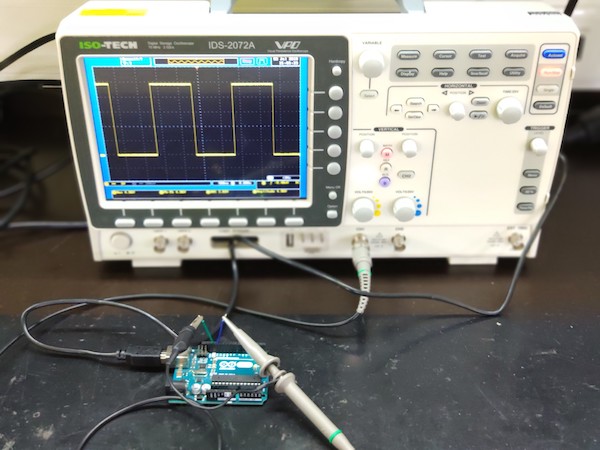
And found out that that voltage and the signal frequency was accordingly with this simple program: