5. Electronics production
Group assignments
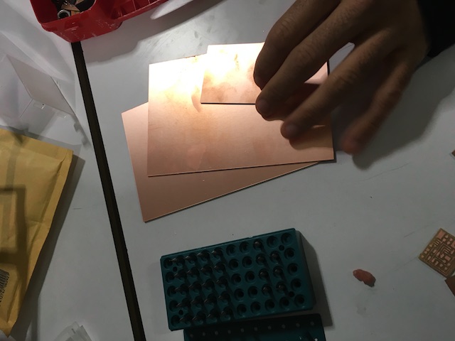
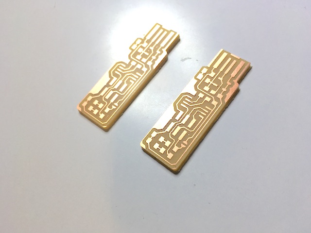
PCB fabrication
Research
Material options
According to flammability characteristics, we can divide PCB into
94VO, V-1, V-2, 94HB
94HB: Normal cardboard (non- fireproof, the lowest grade material, cannot be made as power plate)
94V0: flame retardant cardboard,
22F: single-sided fiber glass board
CEM-1: single-sided fiber glass board
CEM-3: double-sided half-glass board (cheaper than FR-4)
FR-4: double-sided fiber glass board which includes epoxy film ,copper tape and teflon for high frequency boards
more layers = more cost
Designing
Factors to consider: mill diameter, V end mill or Flat end mill. Flat end recommended for even traces. V end might give more precise cuts when calibrated correctly.
Tracing and cutting are two processes that are basic to production of boards:


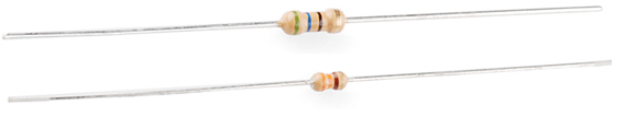
Vias and revets can be used for connections in through hole boards. Easier for prototyping.
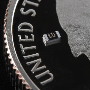
Surface mount parts are much smaller and compact yet harder to attach on the board by a human.
Decoding surface mount markings
SMD resistors, like those in 0603 or 0805 packages, have their own way of displaying their value. There are a few common marking methods you’ll see on these resistors. They’ll usually have three to four characters – numbers or letters – printed on top of the case.
If the three characters you’re seeing are all numbers, you’re probably looking at an E24 marked resistor. These markings actually share some similarity with the color-band system used on the PTH resistors. The first two numbers represent the first two most-significant digits of the value, the last number represents a magnitude.
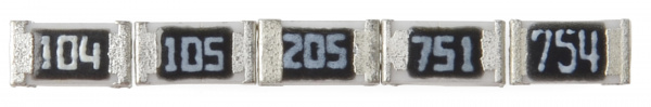
In the above example picture, resistors are marked 104, 105, 205, 751, and 754. The resistor marked with 104 should be 100kΩ (10x104), 105 would be 1MΩ (10x105), and 205 is 2MΩ (20x105). 751 is 750Ω (75x101), and 754 is 750kΩ (75x104).
Fabricating
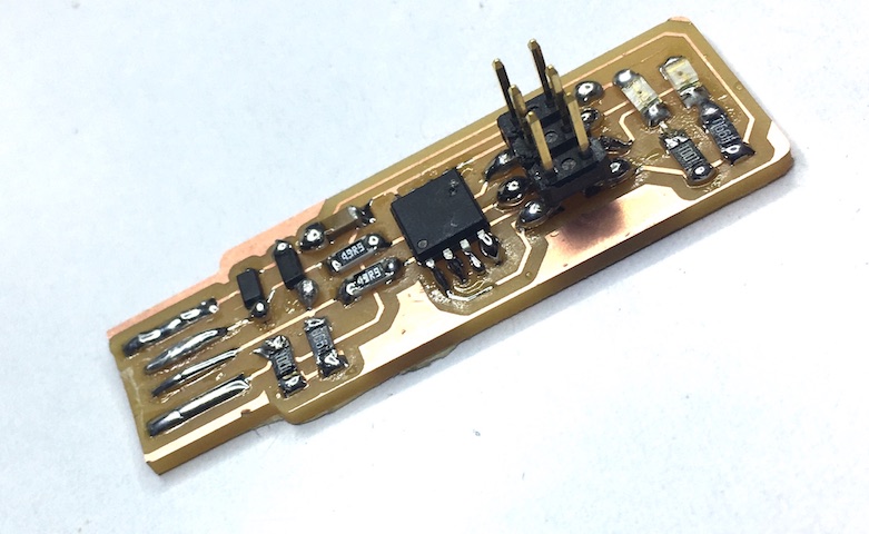
Soldering: eutectic metals. Ensure shiny and smooth solders. ROHS soldering for large volumes, not prototyping. Clean the tip and kep it shiny with some solder and wet sponge. Ventilate while soldering.
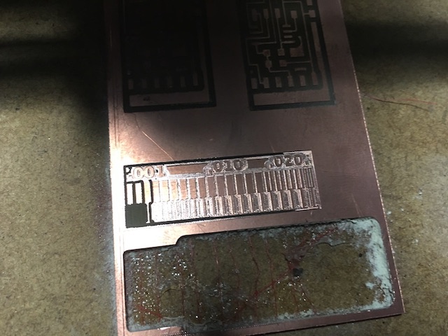
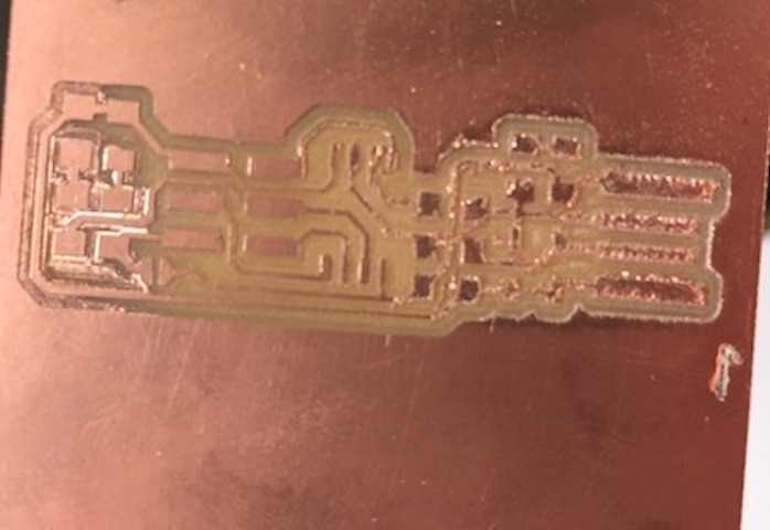
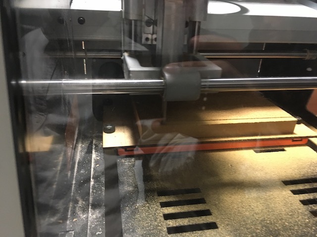
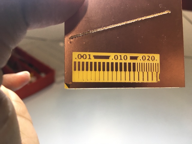
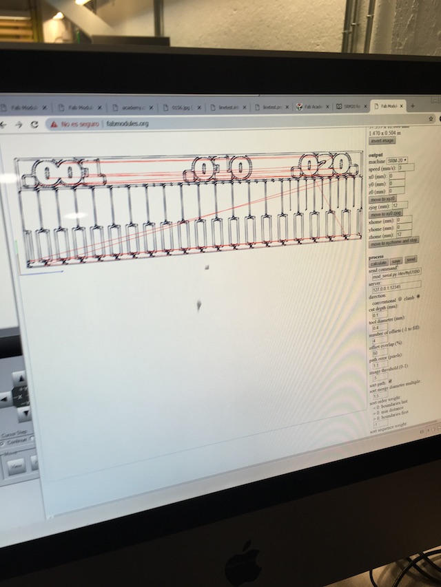
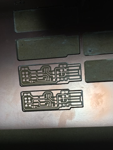
Making test pattern for milling radius checkup
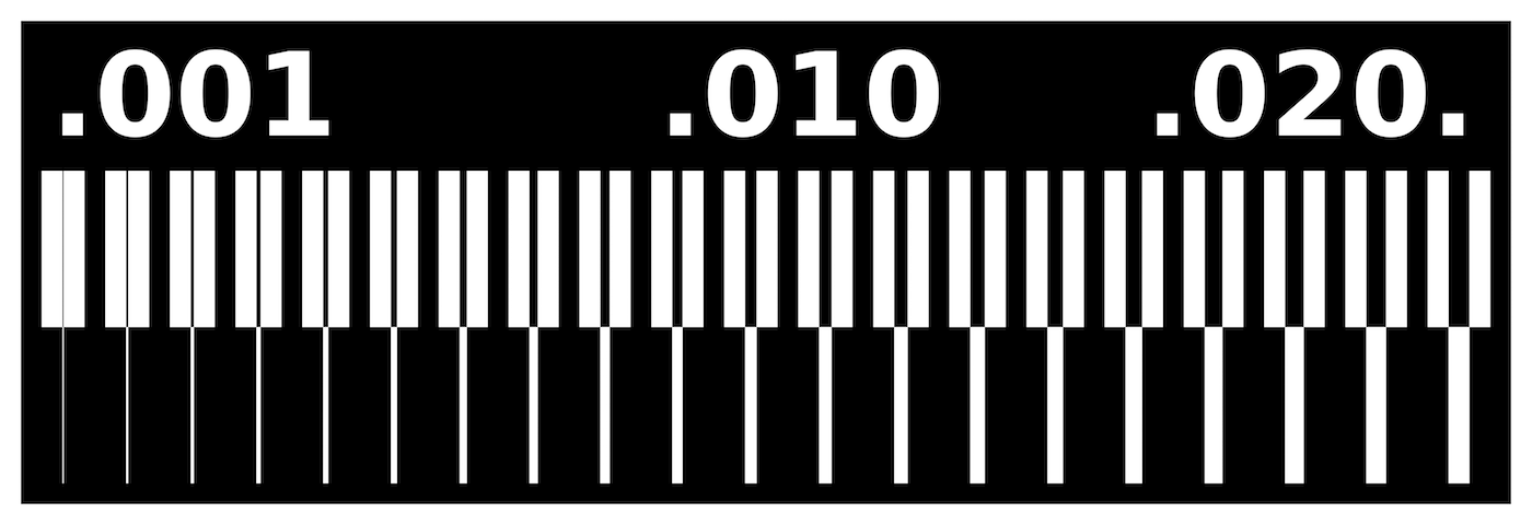
We used the 1/64” head to mill the test pattern to check the minimum size the head can cut. This was a way for us to understand how the mill works.
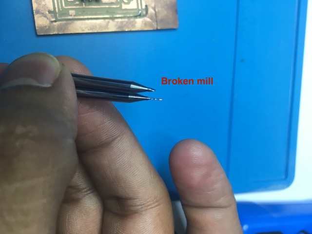
We encountered callibration issues mostly in being able to keep the mill head without breaking and also setting the right Zeta coordinate.
Also, when we used 4mm/s on a new tool, we broke it, so we started new tools off with 50% speed in the roland page.
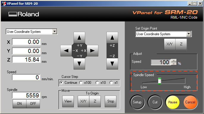
Machine set up and calibration
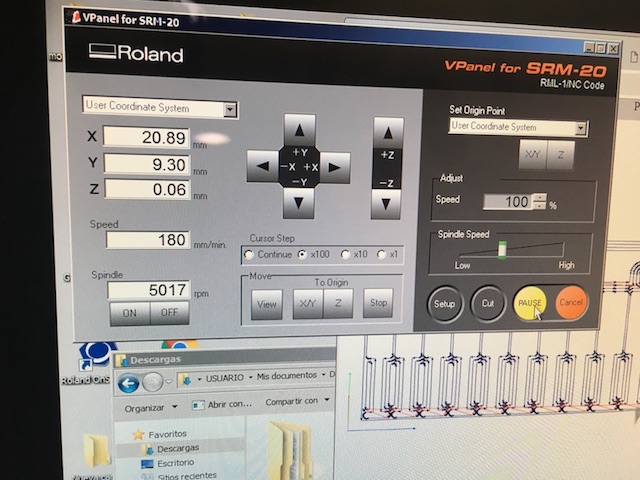
Test cut results and inferences
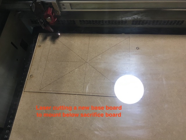
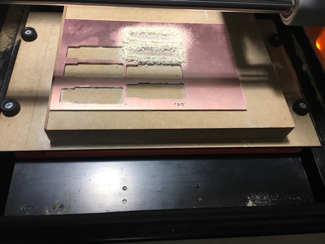
The base was found to be uneven since the cut depths were not even on all four sides. We later found out that this was due to uneven amounts of glue on the backing.
Hence we cut a new seater base on MDF with the laser cutter and checked its level before mounting it. We later found that this is a recommended process before starting a new project.
The new base:
Level check:
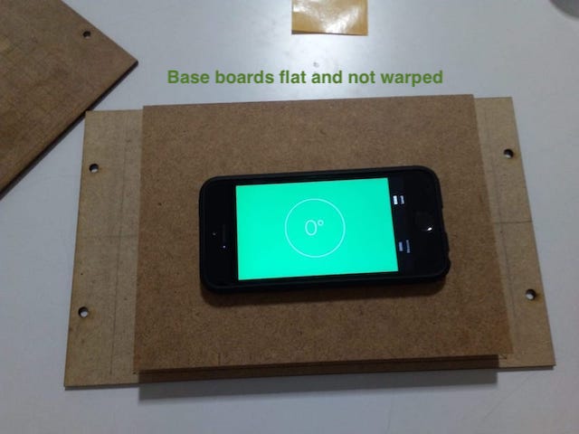
Perfect level!
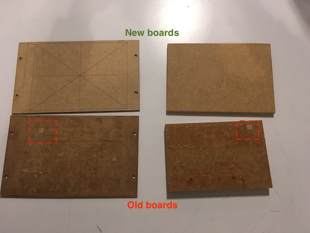
Comparision between the old and new boards. The multiple squares drawn on the previous sacrificial board was a design defect since some of the squares come off after regular use and cause level imbalance.
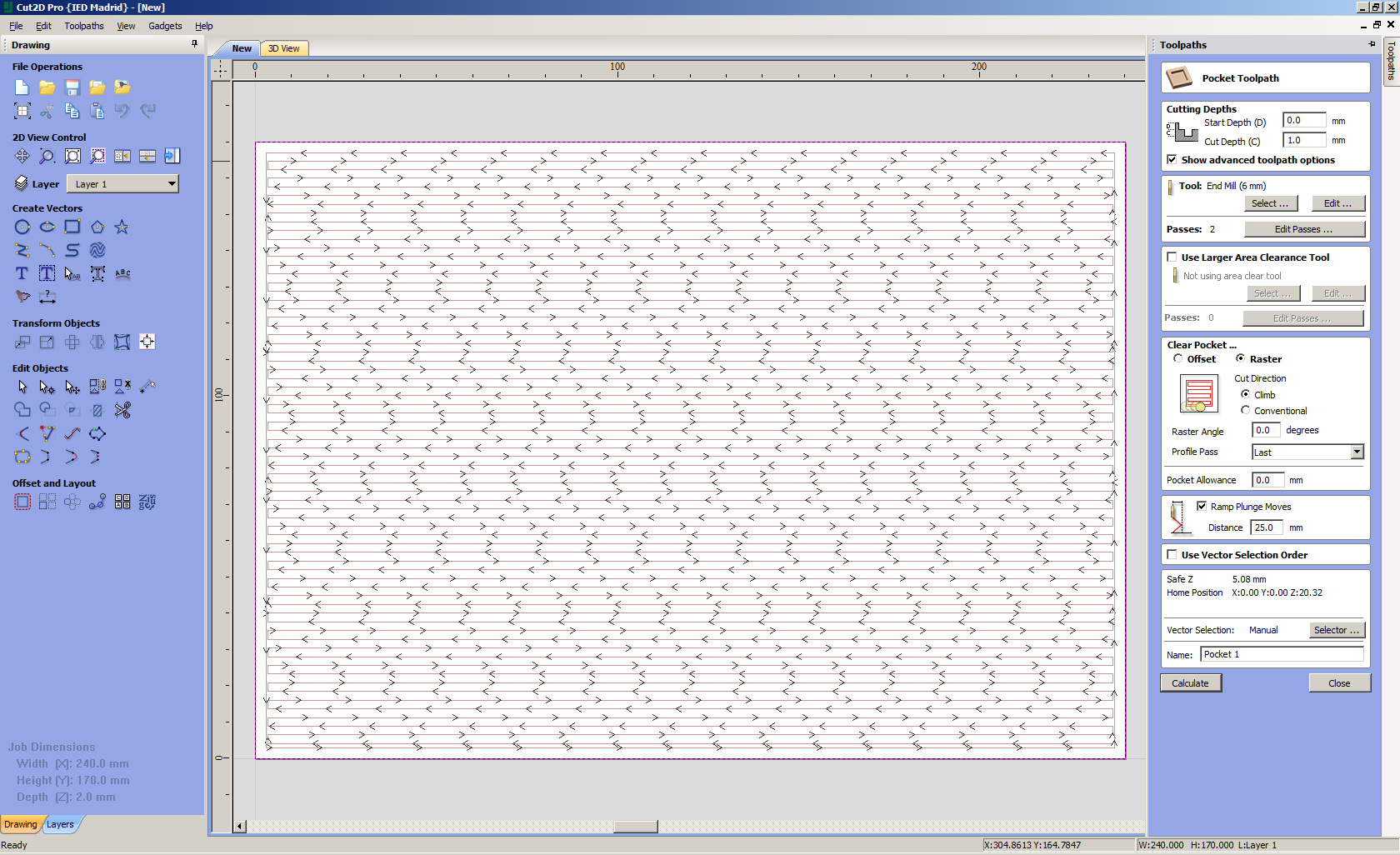
We then fit the MDF sacrificial board of 19mm thickness onto the base and milled away the top layer with a 1/4” tool to match the level that the router is calibrated to.
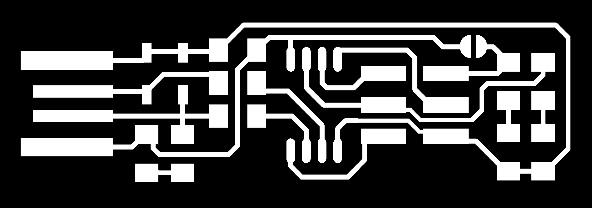
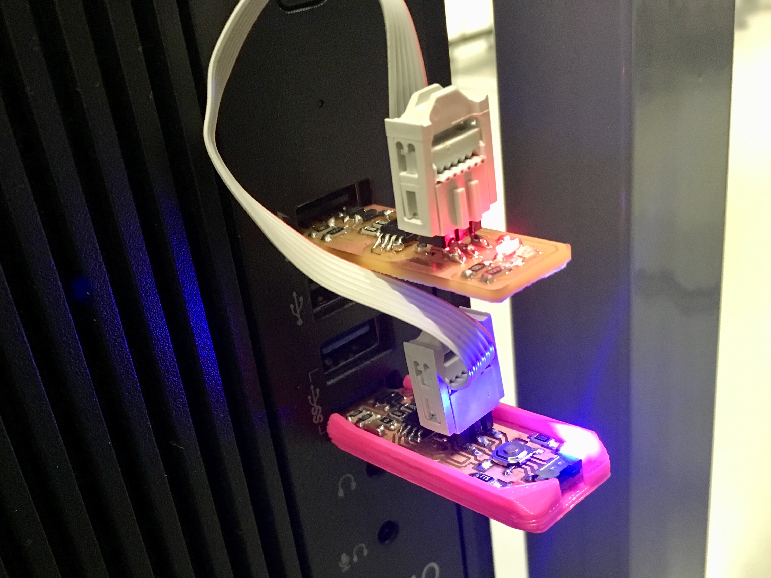
Building the Fab TinyISP
The dust was vacuumed from the mill and not blown, to reduce scratching.
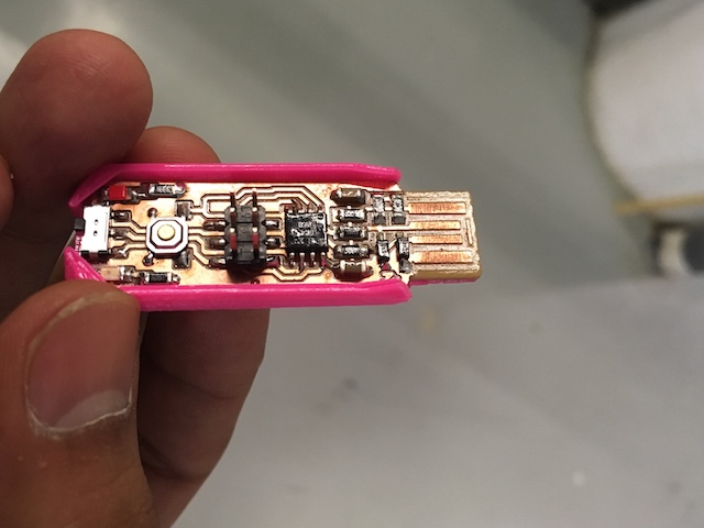
Power Test
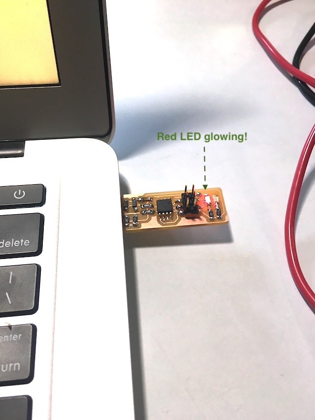
My board has power!
Programming
In circuit programmer
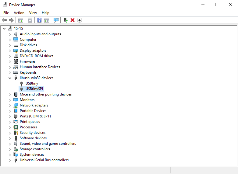
I used the programmer made by my instructor which was a TinyISP type as well with AT44.
System programmer
On my Mac OS, after downloading and installing CrossPack,
I opened terminal and ran the following code:
cd ~/fts_firmware_bdm_v1
make
This gave me a fts_firmware.hex file.
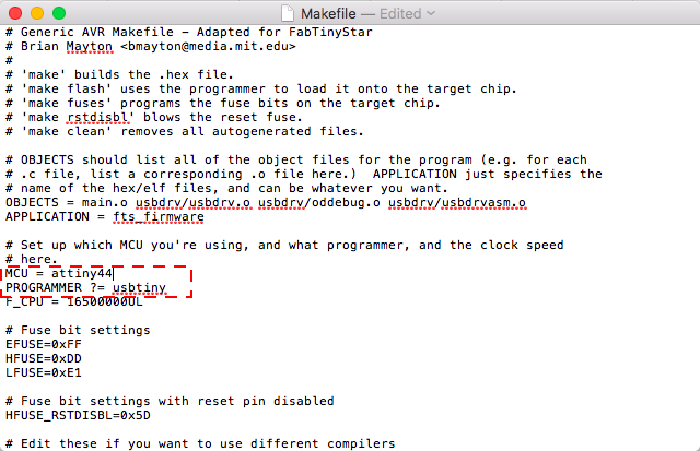
I opened the Makefile and checked for the following:
PROGRAMMER ?= usbtiny
Now I went bact to terminal and ran
make flash
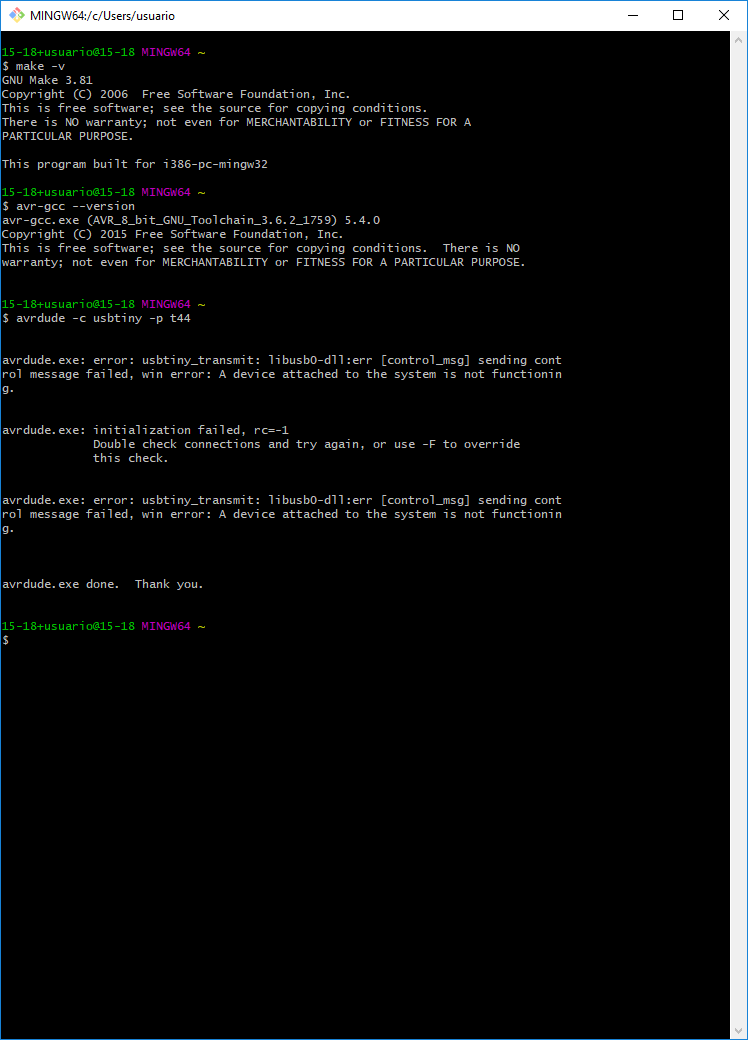
And I got this error:
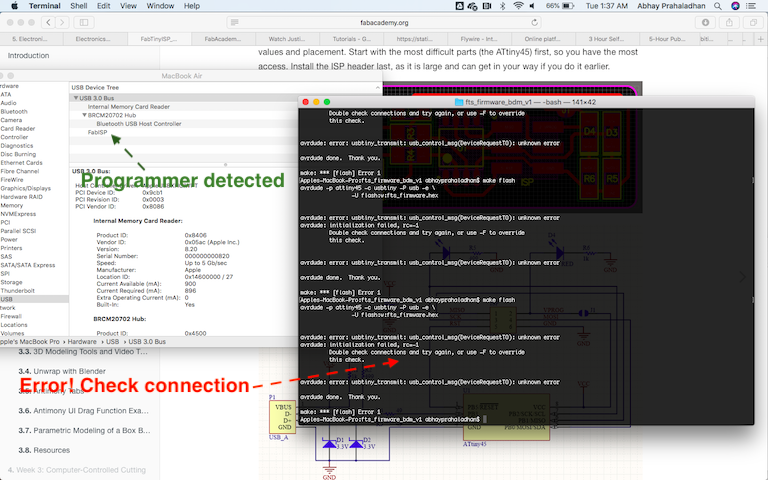
I have a USB 3.0 port, I wonder if thats the issue..
Debugging
I’m using the following approaches to resolve this error:
Visual check: Look for excess solders or floating components on programmer & programme. DONE
Multimeter check: Look for shorts and complete resistances. DONE
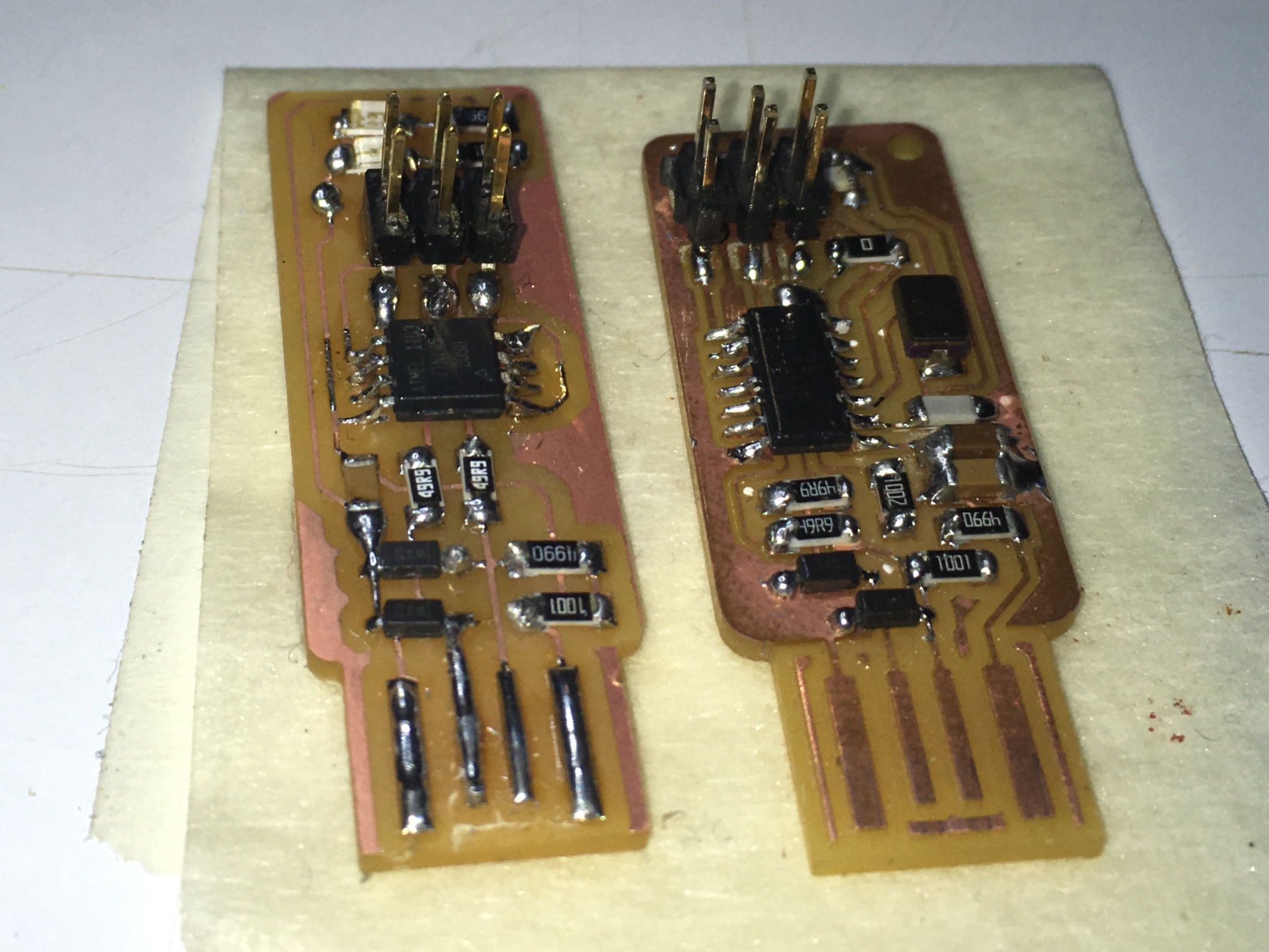
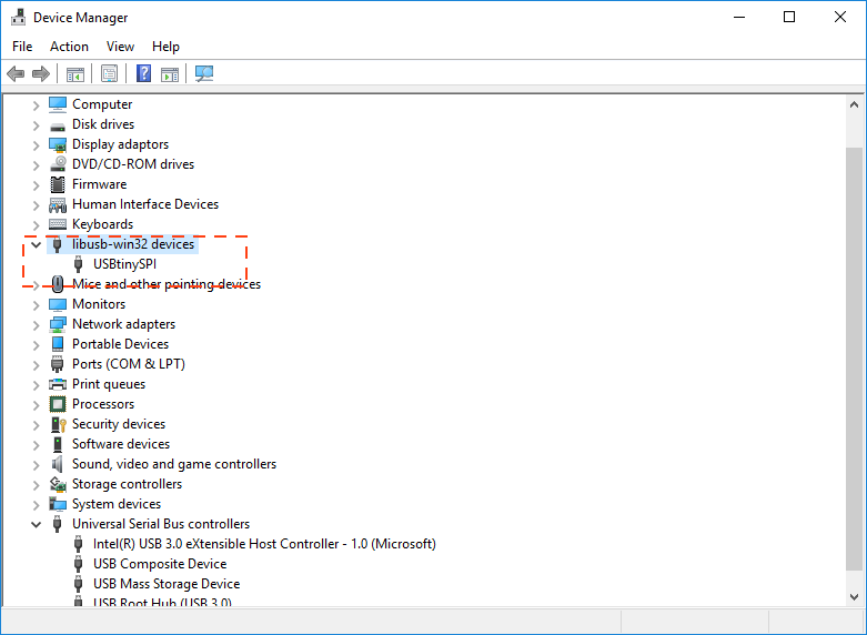
Connector check: Orientation and relay. I was using a programmer board with an ATTiny44 board on it which I realised *might have been causing some issues, so I checked the connector terminals with my board to ensure the terminals matched.
They dont match!!
I’m moving to the programmer board with the ATTiny45 on it.
Test on another computer OS:
I next tried programming my board on a Windows 10 machine with a USB 2.0 port for the programme and 3.0 for the programmer (i had no other ports left).
Make Flash Command finally works!!
make flash
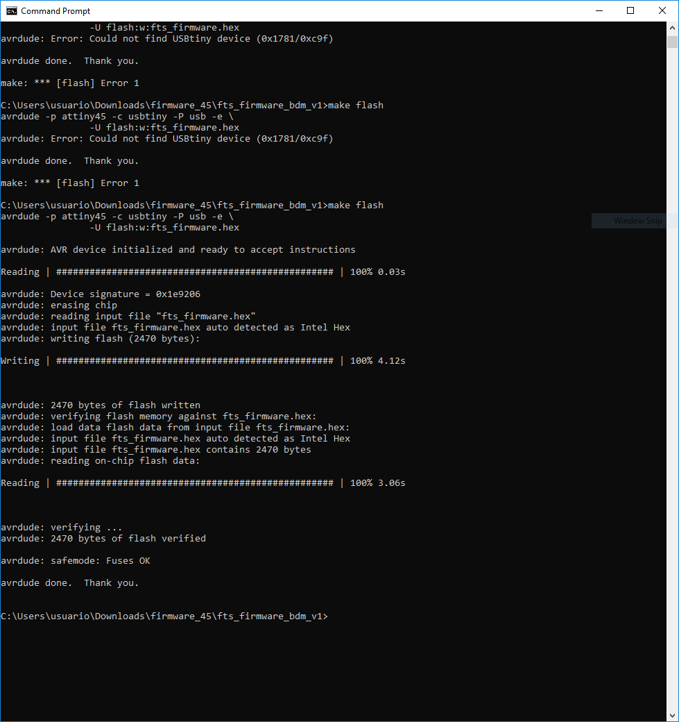
Make fuses command works too
make fuses
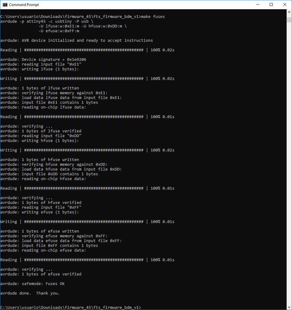
Check if my new programmer works It DOES
Then I ran the following command:
make rstdisbl

HOORAH!
Original files
- Laser cutting file for a 4mm MDF seater for the Roland SRM-20(Illustrator)
- Milling file for base sacrificial board calibration with 1/4” mill head
- Roland SRM-20 file for calibration with 1/4” mill head
- Eagle files for future design
- Makefile for AT45