11. Input devices
This week I worked on defining my final project idea and started to getting used to the documentation process.
Research
Distance
-
- ATTiny processor clock
-
- Set timer counter in C
-
- Tell it how fast to count
-
- 8bit counter can overflow so software counter should count overflows
-
- Turn on trigger pulse , clear counter, wait
-
- Low byte and high byte
-
- Sonar converts time of reflection to distance
-
- Pick clock source based on resolution required- refer datasheet
Hall effect sensor
Can measure magnetic field. Accurate enough to measure earth’s magnetic field. Can be used to check if sensor is facing up or down.
Step response
ADC subtract for removing background noise Use vinyl cutter for making the sensor electrodes
Production of Processor board for Sonar sensor
I followed the tutorial of a previous FabAcademy student Szilard and made a smaller board with a more organised layout.
Components
- ATTiny 45
- R1 10kOhms
- C1 1muF
- 2x3 pin ISP header
- FTDI 1x6 pins
- 1x4 pin sensor socket
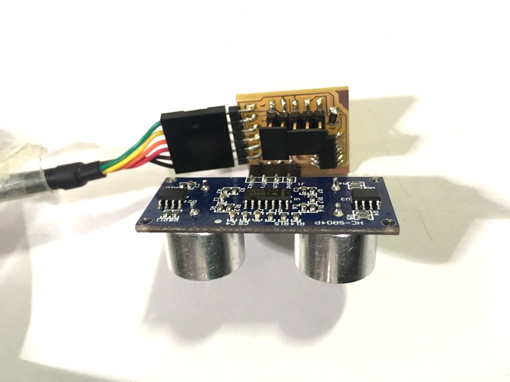
- Ultrasonic sensor module HC-SR04
- 2x2 pin connector bus for networking
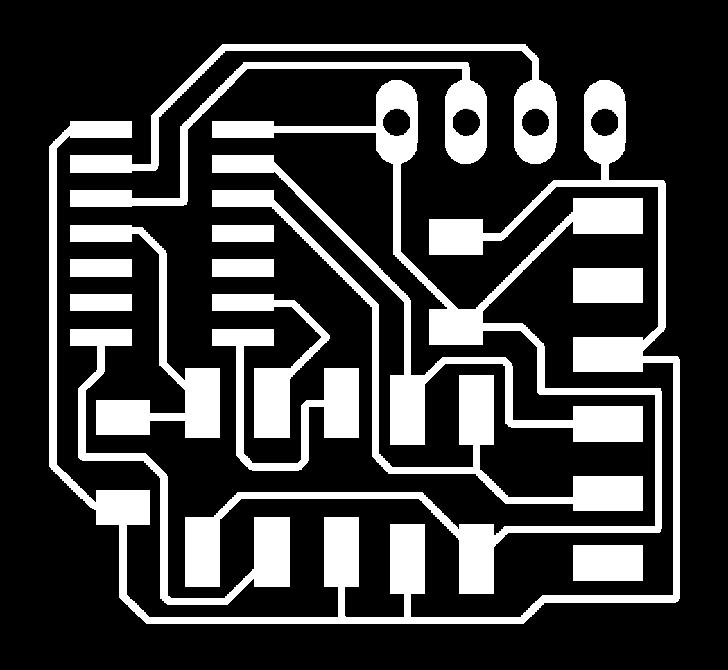
Board Design
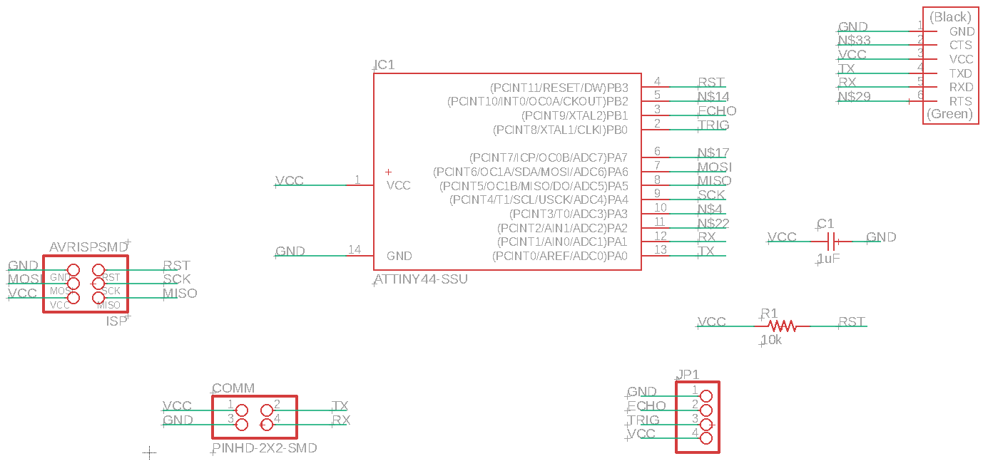
Using the datasheet, the pins for each function was determined.
The board uses an ATTiny 44 to process the data from the HC-SR04.
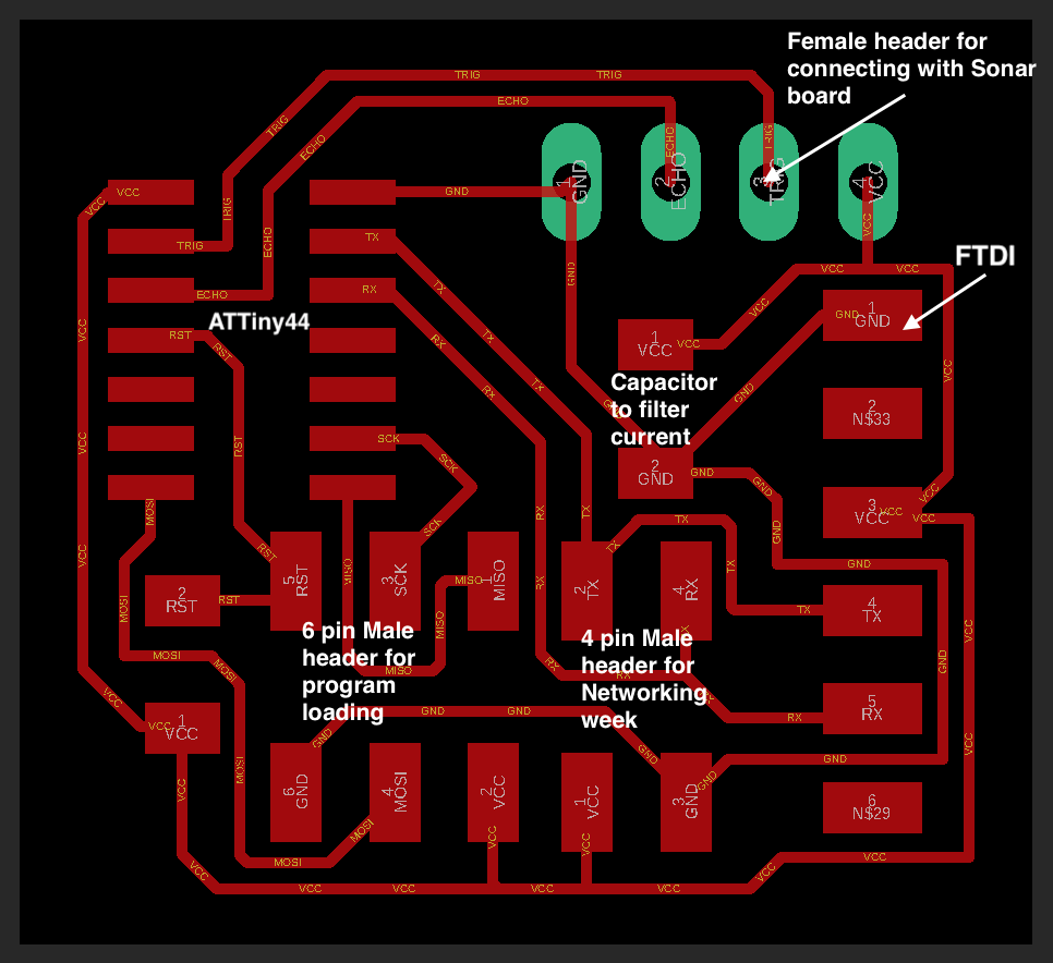
Ports on side B are being used fro trigger and input from the sonar board through the 4 pin female connector JP1 and the ports on side A are used to program through the 6 pin ISP header, networking of data with future boards and for FTDI connection with a computer.
For this board I used a 4 pin header additionally apart from the 6 pin header for future use during the networking week. The Rx and Tx are connected to the same Rx and Tx as the FTDI. I can do the same in my output board to make the input and output boards talk to each other during networking week.
Both the 6 pin and 4 pin headers are placed in line for organisation.
I wanted to add a 20MHz oscillator which would’ve helped refine my data without the need of software. I will do this for the Final project.
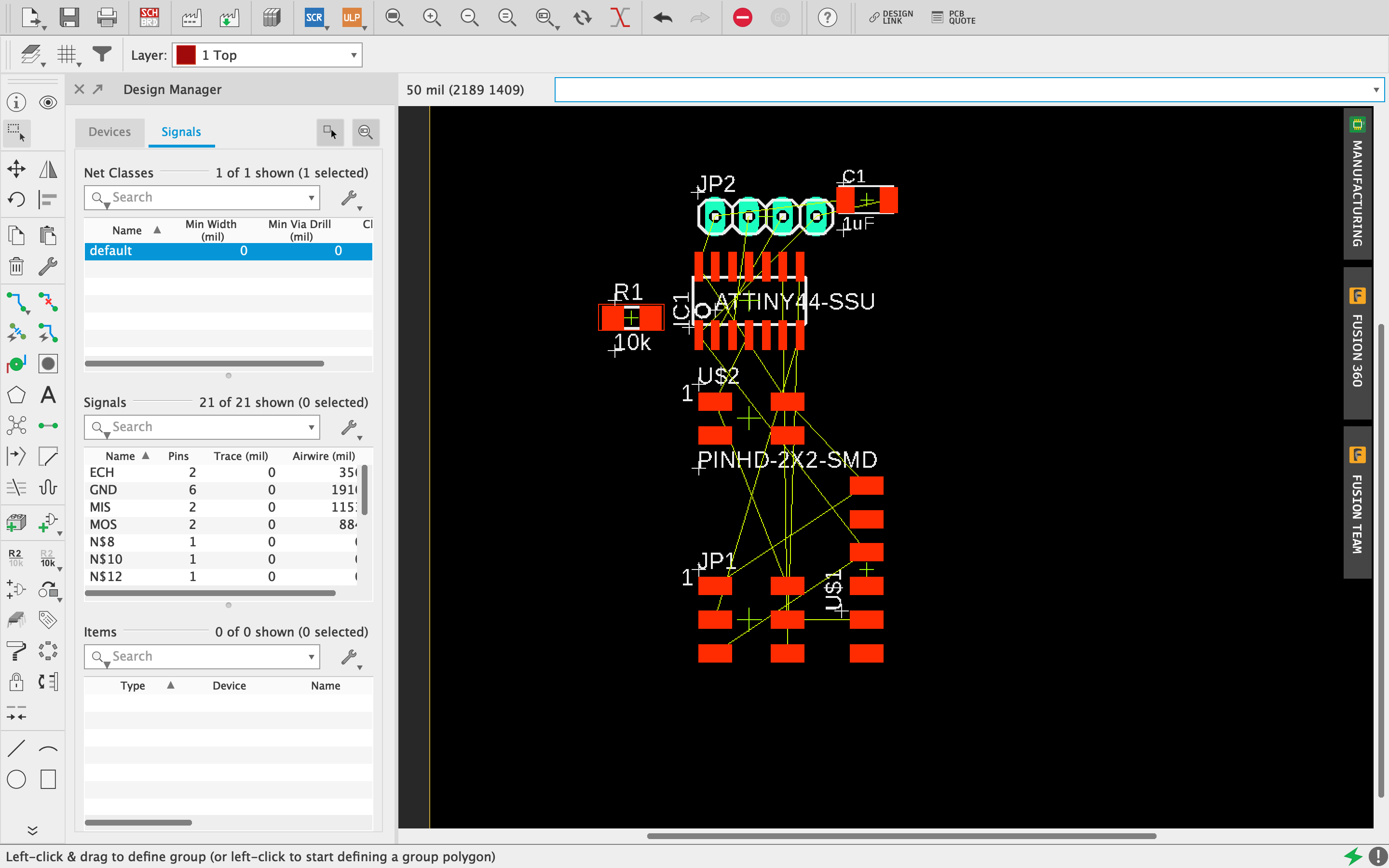
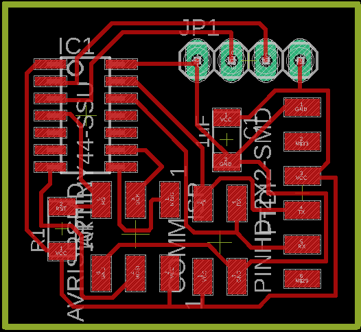
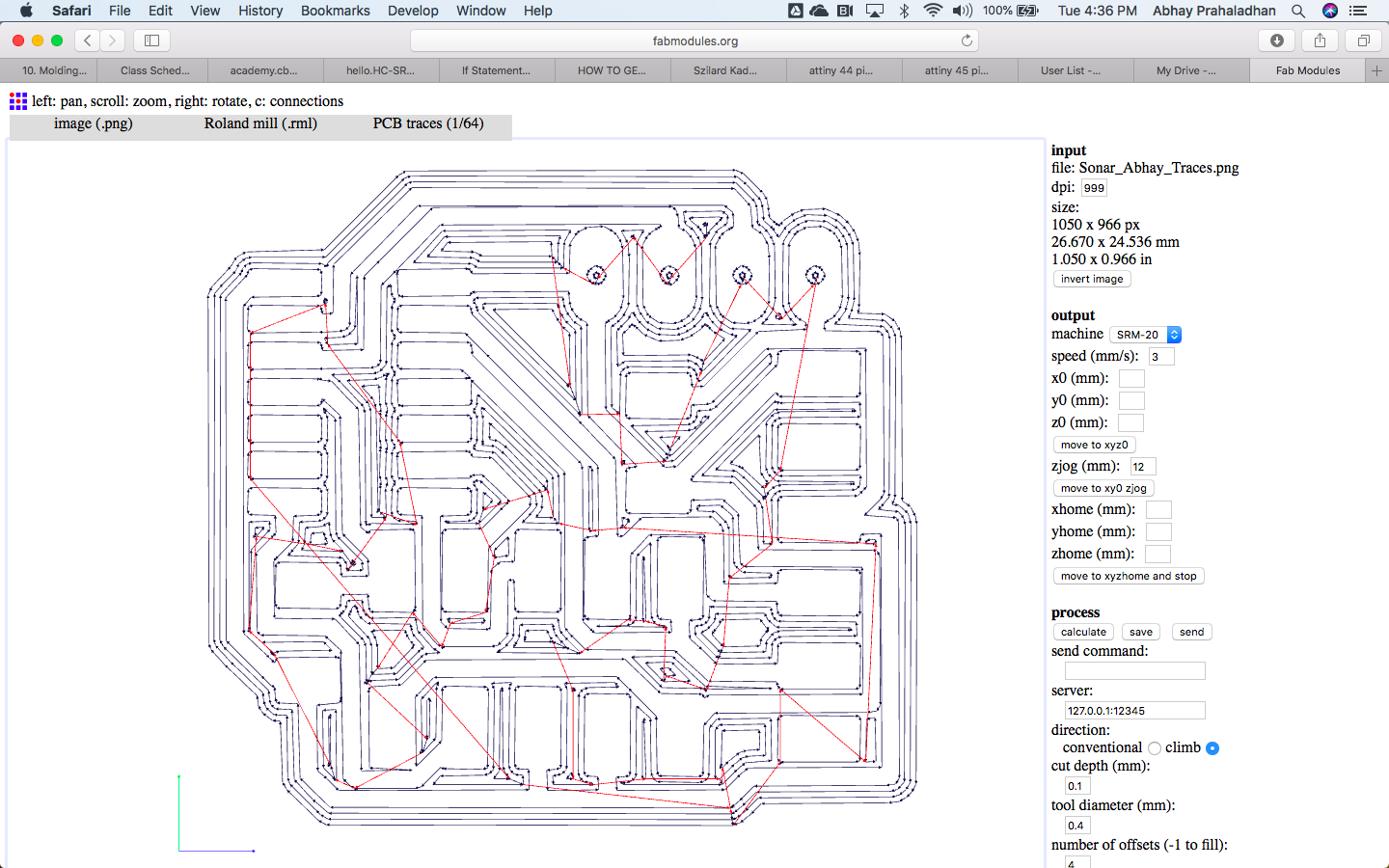
Production
Milling the traces was pretty straightforward and same as previous assignments.
Issues faced
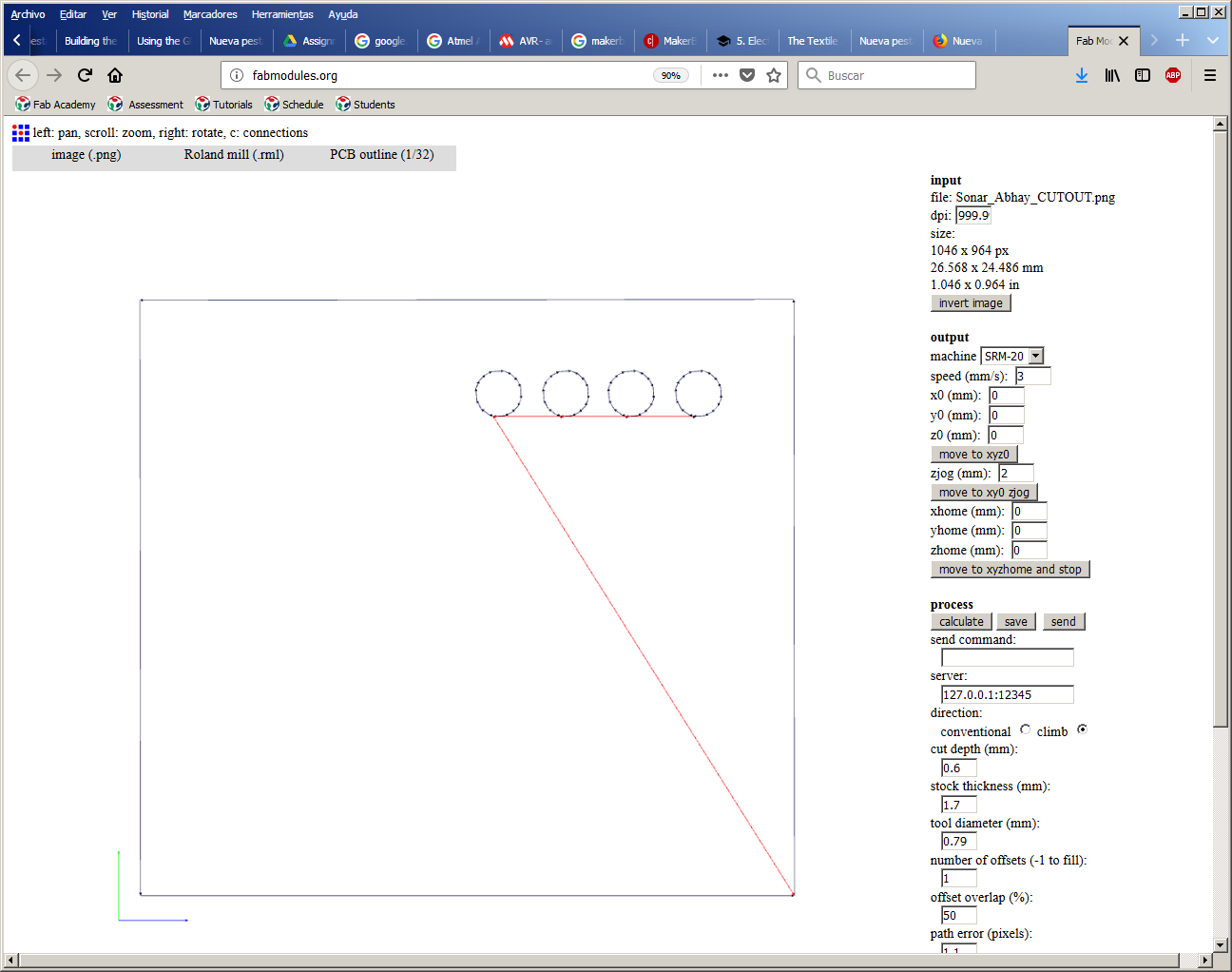
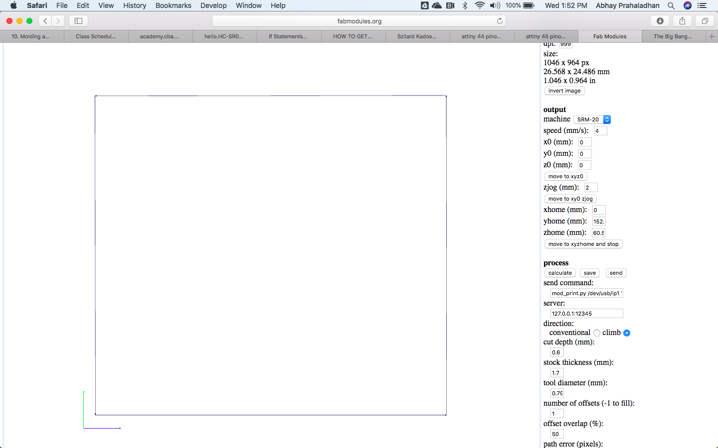
- I tried my best to automate the drill holes for the sensor through the Roland and Fabmodules with no avail. I had to manually make the holes using a Dremel.
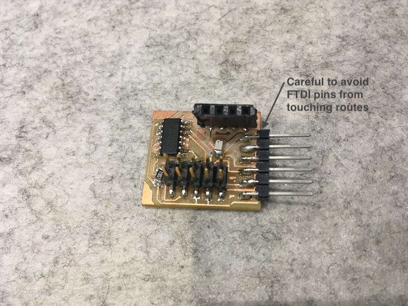
- I noticed that my board was not powering the FabISP board and checked the connections to see that my FTDI headers were touching the copper circuit. I had to make a new board since i ripped out the FTDI pins while trying to correct this. FTDI pin solders need to be made stronger and angled correctly so that they dont touch unnecessary circuitry.
- The most issues I faced while soldering this board were FTDI > Attiny44> header pins near the processor. Hence I soldered them in the order from toughest to easiest.
- No connectivity when connecting boards directly to a USB 3.0 port. Extension cables solve this issue.
Coding
I used the code from the tutorial with a few modifications. Baud is set at 9600 while viewing the Arduino serial.
The formula conversion value for the distance viewing can be calibrated with a scale.
//include the serial communication library
#include < SoftwareSerial.h >

SoftwareSerial Serial_sw(0, 1); // rx, tx

//define all the needed variables and define the pin numbers
#define echoPin 9 // echo conencted to pb1
#define trigPin 10 // trigger connected to pb0

int maximumRange = 4000;
int minimumRange = 2;
long duration, distance;

//initializing the serial communication and pins for input and output
void setup()
{
Serial_sw.begin(9600);
pinMode(trigPin, OUTPUT);
pinMode(echoPin, INPUT);
}

// the actual program loop
void loop()
{
digitalWrite(trigPin, LOW);
delayMicroseconds(1);

digitalWrite(trigPin, HIGH);
delayMicroseconds(10);

digitalWrite(trigPin, LOW);
duration = pulseIn(echoPin, HIGH);

distance = (duration/2)/29.1; //formula for centimeters feedback or duration/58, can be changed after calibration
//distance = duration/148; //formula for inches feedback

Serial_sw.print("Distance: ");
Serial_sw.print(distance);
Serial_sw.println(" cm");
//Serial_sw.println(" inches");
delay(100);
}
I want to check the viewing angle next.
Downloads
Traces.rml Cutout.rml Sonar Board Sonar Schematic Traces file Cutout file