11. Input devices
IMPORTANT NOTE (OFFICIAL)
The second half of the Fab Academy programme is designed to build on the previous weeks. You will be synthesising information and implementing skills that you were introduced to in the first half of the programme and encouraged to integrate these into your final project proposal.
This week I worked on 2 task(s) on Input devices in order to familiarize with sensors and measurement processes. These were the assignments:
-
Group assignment:
Measure the analog levels and digital signals in an input device
On this week we have tested a potentiometer on the previously designed and produced PCB. We tested a piece of a Processing 3D generation code to have a visual representation of the potentiometer’s interaction while checking it on the oscilloscope’s interface.
(Follow this link to see the group assignment) -
Individual assignment:
Measure something: add a sensor to a microcontroller board that you have designed and read it.
SUMMARY
-
Have you?
1. Described your design and fabrication process using words/images/screenshots or linked to previous examples > DONE
2. Explained the programming process/es you used and how the microcontroller datasheet helped you > DONE
3. Explained problems and how you fixed them > DONE
4. Included original design files and code > DONE
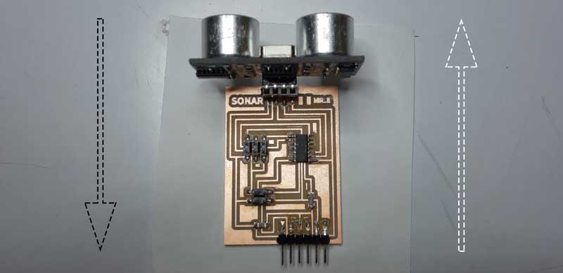
ASSIGNMENT | Individual - Ultrasound to measure distances
I used the Szilárd A. Kados example to produce and program the board. In his case, a 2x2 pin header communication port is added to the board in order to allow future comunications.
I also searched for other ultrasonic sensor info on the web, and found very interesting the Complete Guide for Ultrasonic Sensor HC-SR04 with Arduino from Random Nerd Tutorials. It supported me to understand the code used in different cases.
How it works (physical principle)
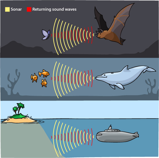
Source > Ask A Biologist Arizona State University
This distance measure system is used in many cases, like in ship sonar seabed mapping or bat echolocation. The principle is that an ultrahigh frequency sound is emmited so its bounce on surfaces on the perpendicular direction is received to then calculate the distance between source and target by the principle of the sound speed transmission, about 340 m/s in air, 1500 m/s in water, and 6000 m/s in stone.
Ultrahigh frequencies on sound means low energy but very directional waves.
When using a sensor, sound is converted to electrical pulses and then known as audio. In this case, the source is a speaker that is moved by voltaje variation creating sound waves by air pressure changes. The sound wave travels to the perpendicular and nearest surface and returns to the source with the same frequency and direction, where a similar device (transductor-microphone) receives it and translates it again to a voltaje variation.
Ultrasound is considered as non audible sound by humans, which hight frequency hearing limits are around 16.000 and 22.000 Hz.
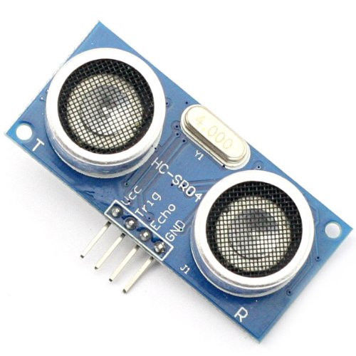
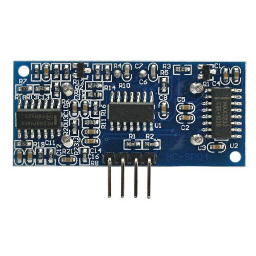
Sensor (description)
The sensor used for this assignment is the HC-SR04. These are its specs:
- Working Voltage: DC 5V
- Working Current: 15mA
- Working Frequency: 40Hz
- Max Range: 4m
- Min Range: 2cm
- Measuring Angle: 15 degree
- Trigger Input Signal: 10µS TTL pulse
- Echo Output Signal Input TTL lever signal and the range in proportion
- Dimension 45 * 20 * 15mm
(Source > www.electroschematics.com)
Circuit design
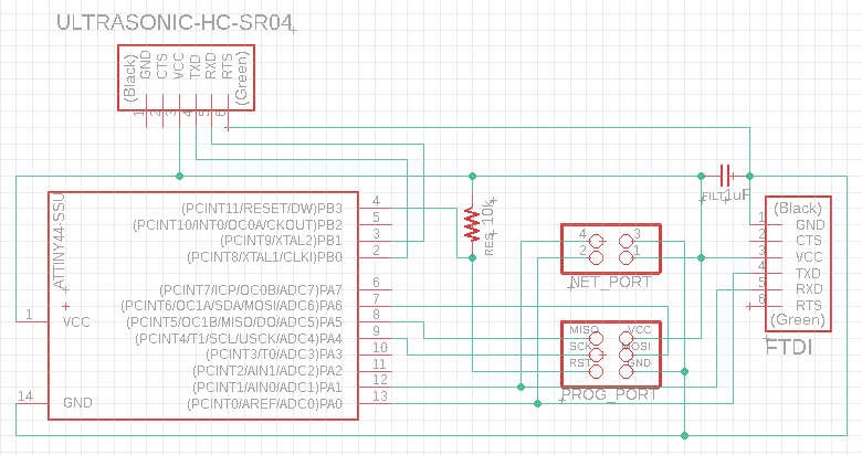
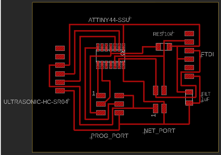
I used Eagle to draw the circuit and the traces .png.
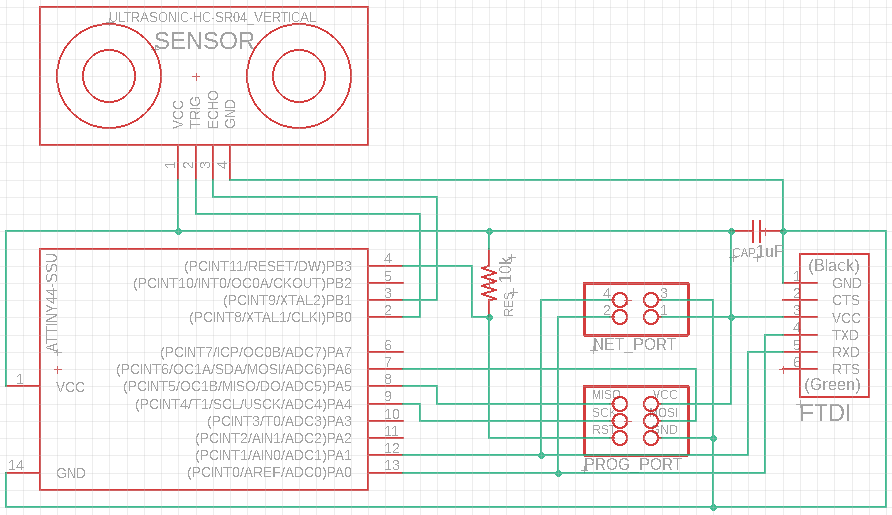
This is the final scheme
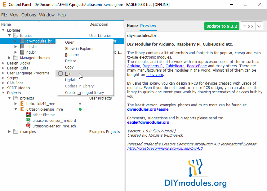
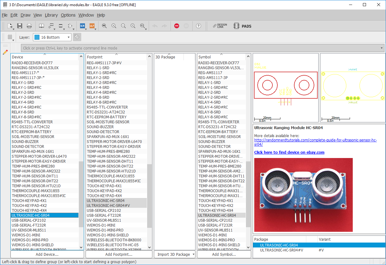
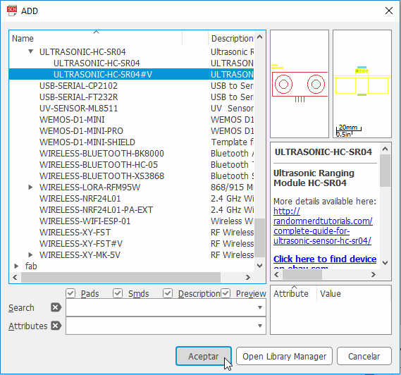
The first thing I did in the drawing process was to search a library in where the sensor footprint was included. I found the DIY one.
Here I show how the to prepare it in Eagle after copying it to the Libraries’s Eagle folder:
When drawing the traces on the board file I decided to change the sensor footprint because the one on the DIY libray was prepared to make holes on the board, and I prefered to sold a 4 female header in which connect the sensor than the sensor itself.
I used the FTDI footprint because the fooprint distance was the same.
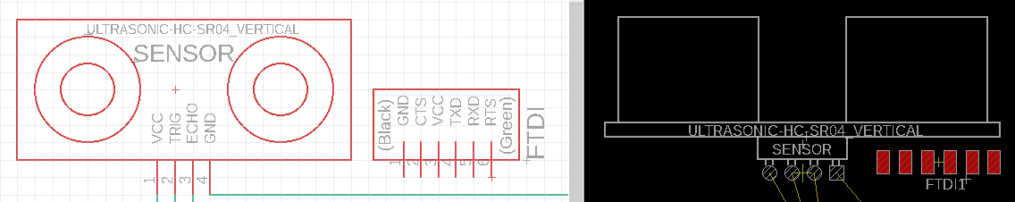
Here are both the final schematics and board screenshots:
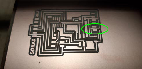
Board production
I used the Roland monoFAB SRM-20 to trace and cut my board with 1/64’‘ and 1/32’‘ mills. First attemp was fine, but there was a problem with one stretch space that was not cut.
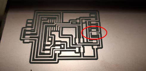
I decided to use Photoshop to fix that little bit error, and also to customize my board. Anyway, this fine drawing solution could be done by downscaling the Eagle’s grid to allow the trace to be drawed/moved more centered between other traces or stretch spaces.
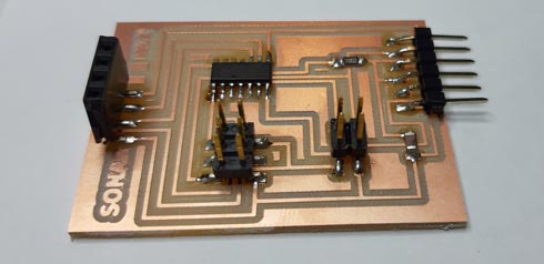
This was the result:
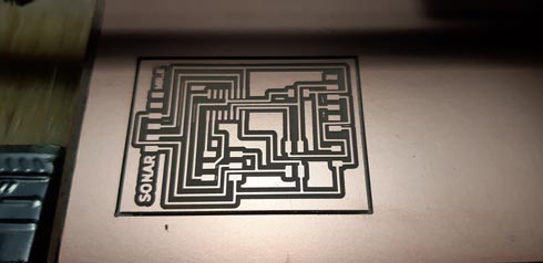
With that second milling job and the cut one the board was fine and ready to add the components, that were these ones:
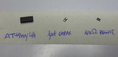
ATtiny 44 microcontroller / 1uF capacitor / 10kΩ resistor
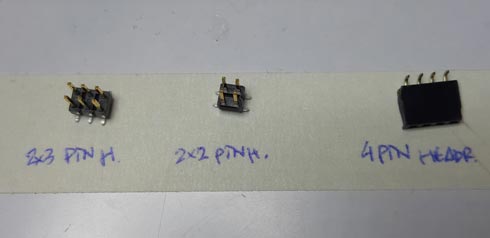
2x3 pin header / 2x2 pin header / 4 pin header
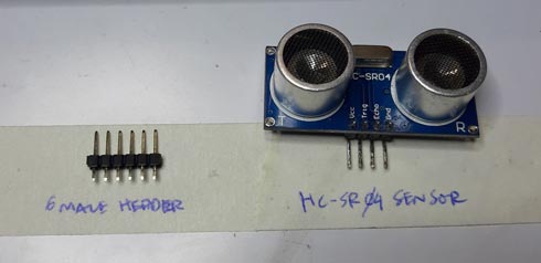
6 male header / HC-SR04 ultrasonic sensor
Solding was easy, but the tin I used appeared to be not very good.
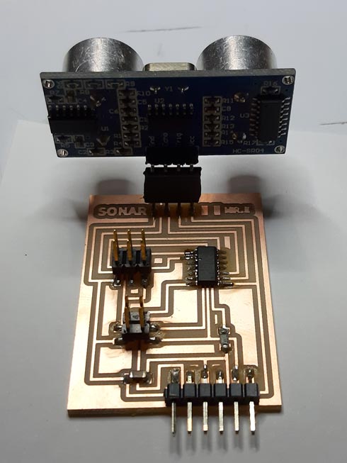
One hero shot!
Programming
I used 2 codes to test the sensor, the Dejan Nedelkovski one, and the Szilárd A. Kados one:
Dejan Nedelkovski code:
/*
  Ultrasonic Sensor HC-SR04 and Arduino Tutorial

  by Dejan Nedelkovski,
  www.HowToMechatronics.com

---

  Modified by Mr.E
  http://fabacademy.org/2019/labs/ied/students/eduardo-segovia/
  Fab Academy 2019

  Changes/Notes made are marked with:
  MR.E >
*/

// MR.E > Include SoftwareSerial library to print results on console
#include <SoftwareSerial.h>

//MR.E > define serial pins
SoftwareSerial mySerial(0, 1);

//MR.E >  define echo and triger pins
const int trigPin = 10;
const int echoPin = 9;
/*
MR.E > I changed 2 and 3 ATtiny44 pins (where the real echo and triger are connected) to 10 and 9 from Arduino:
Consider pin translation between Arduino and ATtiny44: http://fabacademy.org/2019/docs/FabAcademy-Tutorials/week08_embedded_programming/attiny_arduino.html
*/

// define variables
long duration;
int distance;

//MR.E >  define initial setup
void setup() {
  pinMode(trigPin, OUTPUT); // Sets the trigPin as an Output
  pinMode(echoPin, INPUT); // Sets the echoPin as an Input
  mySerial.begin(9600); // Starts the serial communication
}

//MR.E > define loop
void loop() {
  // Clears the trigPin
  digitalWrite(trigPin, LOW);
  delayMicroseconds(2);
  // Sets the trigPin on HIGH state for 10 micro seconds
  digitalWrite(trigPin, HIGH);
  delayMicroseconds(10);
  digitalWrite(trigPin, LOW);
  // Reads the echoPin, returns the sound wave travel time in microseconds
  duration = pulseIn(echoPin, HIGH);
  // Calculating the distance
  distance = duration * 0.034 / 2;
  // Prints the distance on the Serial Monitor
  mySerial.print("Distance: cm"); //MR.E > Added "cm"
  mySerial.println(distance);
}
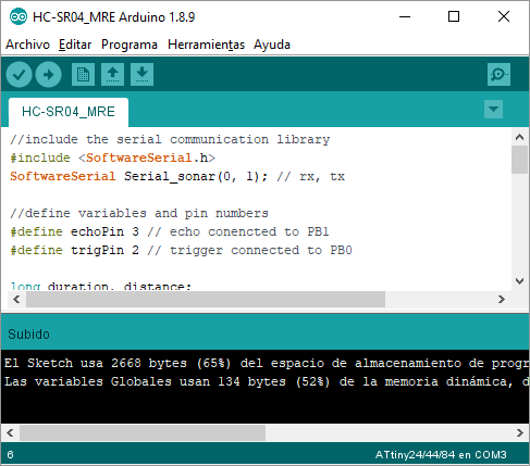
- Szilárd A. Kados code:
//include the serial communication library
#include <SoftwareSerial.h>
SoftwareSerial Serial_sonar(0, 1); // rx, tx

//define variables and pin numbers
#define echoPin 3 // echo conencted to PB1
#define trigPin 2 // trigger connected to PB0

long duration, distance;

//serial communication and pins for input and output
void setup()
{
Serial_sonar.begin(9600);
pinMode(trigPin, OUTPUT);
pinMode(echoPin, INPUT);
}

// the actual program loop
void loop() {
  //send the pulse
digitalWrite(trigPin, LOW);
delayMicroseconds(1000); //each 1 sec we send a pulse
digitalWrite(trigPin, HIGH);
delayMicroseconds(10);
digitalWrite(trigPin, LOW);

//we measuse the time
duration = pulseIn(echoPin, HIGH);

//formula for cm feedback. The sound speed is 340m/s = 29us/cm.
//we divide the pulse time by 58, the time that the pulse takes to go and come back.
distance = duration/58;

//send the information to the Serial Monitor
Serial_sonar.print(distance);
Serial_sonar.println(" cm");
delay(1000);
}
I used my FABtinyISP and Arduino software to burn the bootloader and to upload the code to the sonar board.
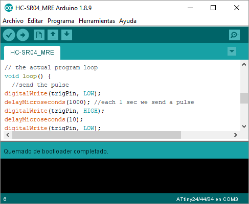
The clock speed must be set to the internal Attiny44 one, which is 8 M(Hz).
(It could be made from Arduino interface by selecting it from Tools>Clock menu and, once selected, burning the bootloader from the Tools menu.
You can see the selected setup on the bottom right corner of the window)Setting succesfuly done!
Code was modified to set the ATtiny44 pins to manage the trigger/echo signals. I changed 2 and 3 ATtiny44 pins (where the real echo and triger are connected) to 10 and 9 from Arduino.
(Consider pin translation between Arduino and ATtiny44)Setting succesfuly done!
Results
Trouble…
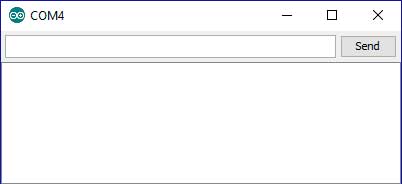
Everything was ok, but the serial window didn’t show anything, just white…
… so I decided to search for solutions:
- review connections > using the multimeter, everything in soldering and continuity appeared to be fine, although tin was not very reliable. PASS
- change the sensor > maybe the sensor was in bad conditions because it was not new (used). I tested with another (used) one. PASS
- test the sensor > using Arduino and breadboard I could discard sensor problems. The sensor was ok. PASS
- check design > looking for missing connections on the schematic file or for design errors on any footprint on the board file, and compare them with the code assignments. FAIL
The FTDI footprint was upside down (mirrored) on the board:
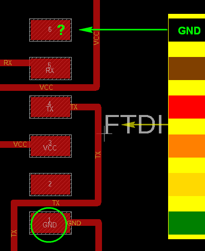
So I just swaped the FTDI wire and everything was successful:
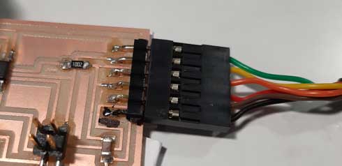
Note that, to remember this peculiarity, the GND pin was painted black
Note: Be careful when drawing the board, remember to image always the final result to control every detail and avoid problems
The working sensor time!
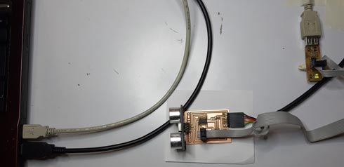
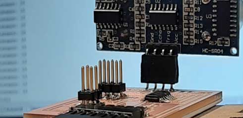
Here, the board with the HC-SR04 ultrasonic sensor connected, pointing to the surface perpendicularly (the notebook screen in this case):
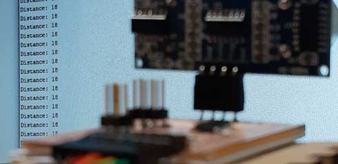
Here, the lecture done printed through serial (18 cm):
See here the sonar running live:
Great ideas (to the drawer, by the moment…)
First thing I had on mind on this week was to modify my previous improved hello.world board.
The target was to use the written code to use the button, the LED and the sensor in and interaction managed by software:
- When pressing once the button, the sensor would begin to send/receive distance measurement, and it would be warned with the LED on state. Also, the serial must show a message like “reading… 200cm… press to stop”
- When pressing again the button, the sensor would stop its activity and the LED would turn off. The message displayed would be the last distance captured.
Preparing to do this, I first decided to test the sensor on the free pins at the ATtiny44 microcontroller of the produced board, using/updating my preovious code with the sensor behaviour integration.
//include the serial communication library
#include <SoftwareSerial.h >

SoftwareSerial Serial_sw(0, 1); // rx, tx

//define all the needed variables and define the pin numbers
#define echoPin 2 // echo conencted to pb1
#define trigPin 3 // trigger connected to pb0

int maximumRange = 4000;
int minimumRange = 2;
long duration, distance;

//initializing the serial communication and pins for input and output
void setup()
{
Serial_sw.begin(9600);
pinMode(trigPin, OUTPUT);
pinMode(echoPin, INPUT);
}

// the actual program loop
void loop()
{
digitalWrite(trigPin, LOW);
delayMicroseconds(1);

digitalWrite(trigPin, HIGH);
delayMicroseconds(10);

digitalWrite(trigPin, LOW);
duration = pulseIn(echoPin, HIGH);

distance = duration/58; //formula for cm feedback
//distance = duration/148; //formula for inches feedback

Serial_sw.print("Distance: ");
Serial_sw.print(distance);
Serial_sw.println(" cm");
//Serial_sw.println(" inches");
delay(100);
}
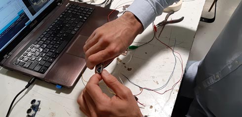
After setting up the appropiate free pins on the ATtiny44 microcontroller (5/11 and 2/3 in my case), I used the 2x3 pin header to connect the sensor to VCC and GND for power supply, and with 2 wires coming from TRIGGER and ECHO, I tested the serial response while manually connecting the wires to the free pins.
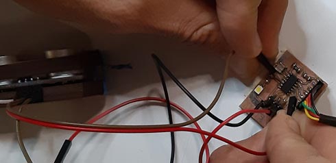
Testing the sensor on the free 5/11 pins
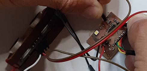
Testing the sensor on the resonator 2/3 pins
For this, I decided to burn again the bootloader to the internal 8 M(Hz) clock speed.
I tested many combinations, like different clock speeds, different serial speeds, trigger/echo alternation… and the response was always 0, but, at least, the code returned the serial message ‘0 cm’.
Sometimes, other values while accidentally touching other parts of the board, appeared. This situation made me though that the sensor was not dead… maybe.
In conclusion, as I couldn’t test the hardware success, I have pending to draw/produce a new board integrating the sensor to the other components to try in a better and ensured way this coding idea.
Files
- Eagle > (schematics/board)
- .png > (traces/cut)
- Code > (Arduino-1 | Arduino-2)
Credits/Links
- Board from Szilárd A. Kados
- Ultrasonic Sensor HC-SR04 and Arduino Tutorial from Dejan Nedelkovski
- Complete Guide for Ultrasonic Sensor HC-SR04 with Arduino from Random Nerd Tutorials
- Ask A Biologist Arizona State University sonar image
- Elena Cardiel‘s assignment
- ATtiny 44A vs. Arduino Pin-Out Numbering