12. Output devices
This week I worked on 2 task(s) on Output devices in order to familiarize with sensors and power consumption measurement. These were the assignments:
-
Group assignment:
Measure the power consumption of an output device
On this week we … .
(Follow this link to see the group assignment) -
Individual assignment:
Add an output device to a microcontroller board you’ve designed, and program it to do something.
SUMMARY
-
Have you?
1. Described your design and fabrication process using words/images/screenshots or linked to previous examples > DONE
2. Explained the programming process/es you used and how the microcontroller datasheet helped you > DONE
3. Explained problems and how you fixed them > DONE
4. Included original design files and code > DONE
ASSIGNMENT
Individual - Speaker to play sound
How it works (physical principle)
Source > www.quora.com
Source > High Fidelity Cables
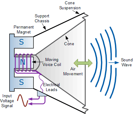
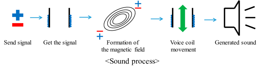
When using a speaker, audio is converted from electrical ‘pulses’ to pressure waves that the speaker produces on the air with its movement. In this case, the source (speaker) is moved by voltaje and magnetic field variation which creates sound waves with the same frequency than the audio one.
Source > Researchgate.net
About the speaker (loudspeaker):
A loudspeaker is an electroacoustic transducer; a device which converts an electrical audio signal into a corresponding sound.
The dynamic speaker operates on the same basic principle as a dynamic microphone, but in reverse, to produce sound from an electrical signal. When an alternating current electrical audio signal is applied to its voice coil, a coil of wire suspended in a circular gap between the poles of a permanent magnet, the coil is forced to move rapidly back and forth due to Faraday’s law of induction, which causes a diaphragm (usually conically shaped) attached to the coil to move back and forth, pushing on the air to create sound waves.
Besides this most common method, there are several alternative technologies that can be used to convert an electrical signal into sound. The sound source (e.g., a sound recording or a microphone) must be amplified or strengthened with an audio power amplifier before the signal is sent to the speaker.
Speakers are typically housed in a speaker enclosure or speaker cabinet which is often a rectangular or square box made of wood or sometimes plastic. The enclosure’s materials and design play an important role in the quality of the sound.Source > Wikipedia
The bass-reflex typical enclosurement of loudspeakers help the sound to be acoustically reinforced:
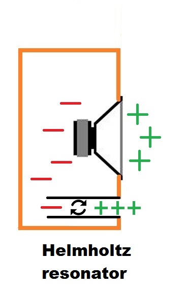
Source > Bass reflex speaker design
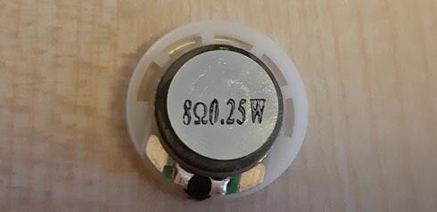
Speaker (description)
PSR-23F08S-JQ (piezo speaker):
| Product Attributes | ||
|---|---|---|
| Categories | Audio Products/Speakers | |
| Manufacturer | Mallory Sonalert Products Inc. | |
| Series | PSR | |
| Part Status | Active | |
| Technology | Magnetic | |
| Type | General Purpose | |
| Frequency Range | 900Hz ~ 6,5kHz | |
| Frequency - Self Resonant | 900Hz | |
| Impedance | 8 Ohms | |
| Efficiency - dBA | 81.00 | |
| Efficiency - Testing | 1W/1M | |
| Efficiency - Type | Sound Pressure Level (SPL) | |
| Power - Rated | 250mW | |
| Power - Max | 300mW | |
| Port Location | Top | |
| Shape | Round | |
| Material - Cone | Polyester, Polyethylene Terephthalate (PET) | |
| Material - Magnet | Ferrite | |
| Termination | Solder Pads | |
| Size / Dimension | 0.906” Dia (23.00mm) | |
| Height - Seated (Max) | 0.197” (5.00mm) |
(Source > www.digikey.es)
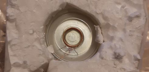
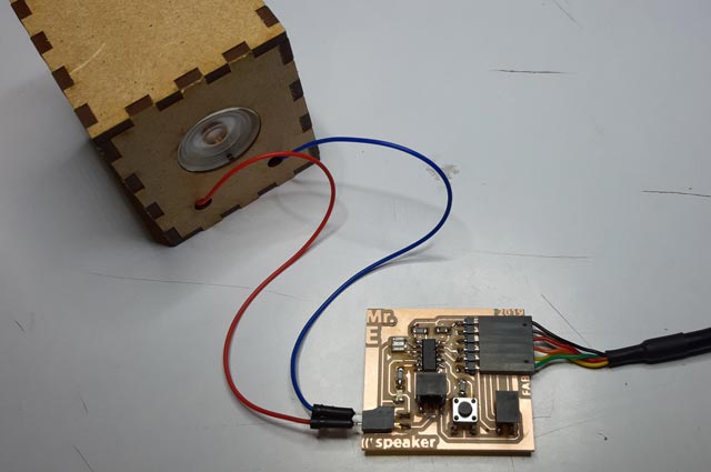
Test
To decide which board I could make, I tested the PSR-23F08S-JQ on my hello-world board free pins. Connecting the speaker to the pin 5 and to the GND, and uploading an example code, this was the result:
TEST VIDEO
Circuit design
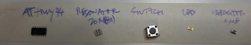
For this assignment I decided to use the ATtiny44 micro-controller according to these reasons:
- First, I wanted to design a board with a simple speaker that could play a sound when a button on the board would be pressed. For that, I wanted to use my hello-world board that had already that behaviour working, and other similar ones, with a LED. In this case, the PSR-23F08S-JQ speaker would work fine, because it doesn’t need any additional power supply over de +5V from the FTDI (computer USB port). I thought that the speaker (pin_,GND) must be connected to a PWM pin to manage the voltaje variations.
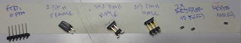
- Secondly, I considered the idea of using also another better speaker that would need an additional power supply. For that, it would be necesary to consider the use of another ATtiny44 pins to add 2x2 power and 2x2 speaker headers, with the support of a MOSFET and a REGULATOR, apart from devices to manage the resistance and the capacitance. In any case, it would be interesenting to have both speaker systems on the same board to check the result difference from one to the other.
- Thirdly, I wanted to add the same 2x2 header than in input devices to allow communications between boards.
- I also considered very important to put the speakers into acoustic boxes to enhace the sound (specially on low frequences) loudness.
- Finally, this speaker-board also has a state LED that also can work as an output. To make it more interesting, the LED works on the pin 5 of the ATTiny44. According to the microcontroller datasheet, this pin works as PWM, as desired to make effects on the light output.
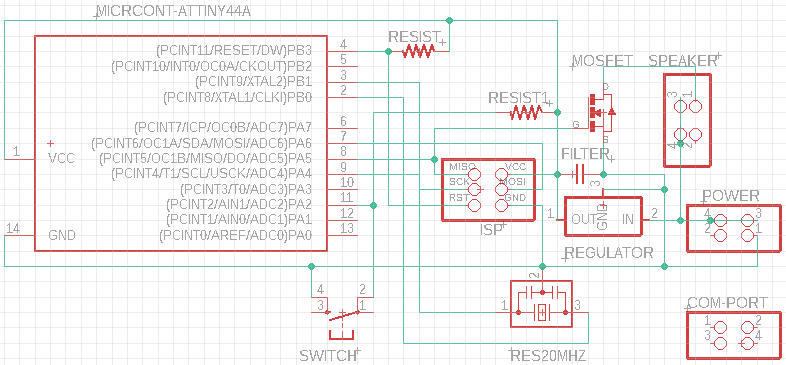
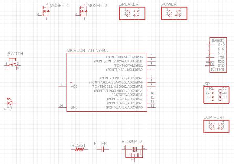
I started using Eagle to modify my hello_world board. I left the LED’s and button’s footprints as they were and I added a 2x2 pin header to connect the piezo speaker. This connection system is independent from the better speaker one. Also, I added a 2x2 comunication port. These are the schematics and traces .PNGs:
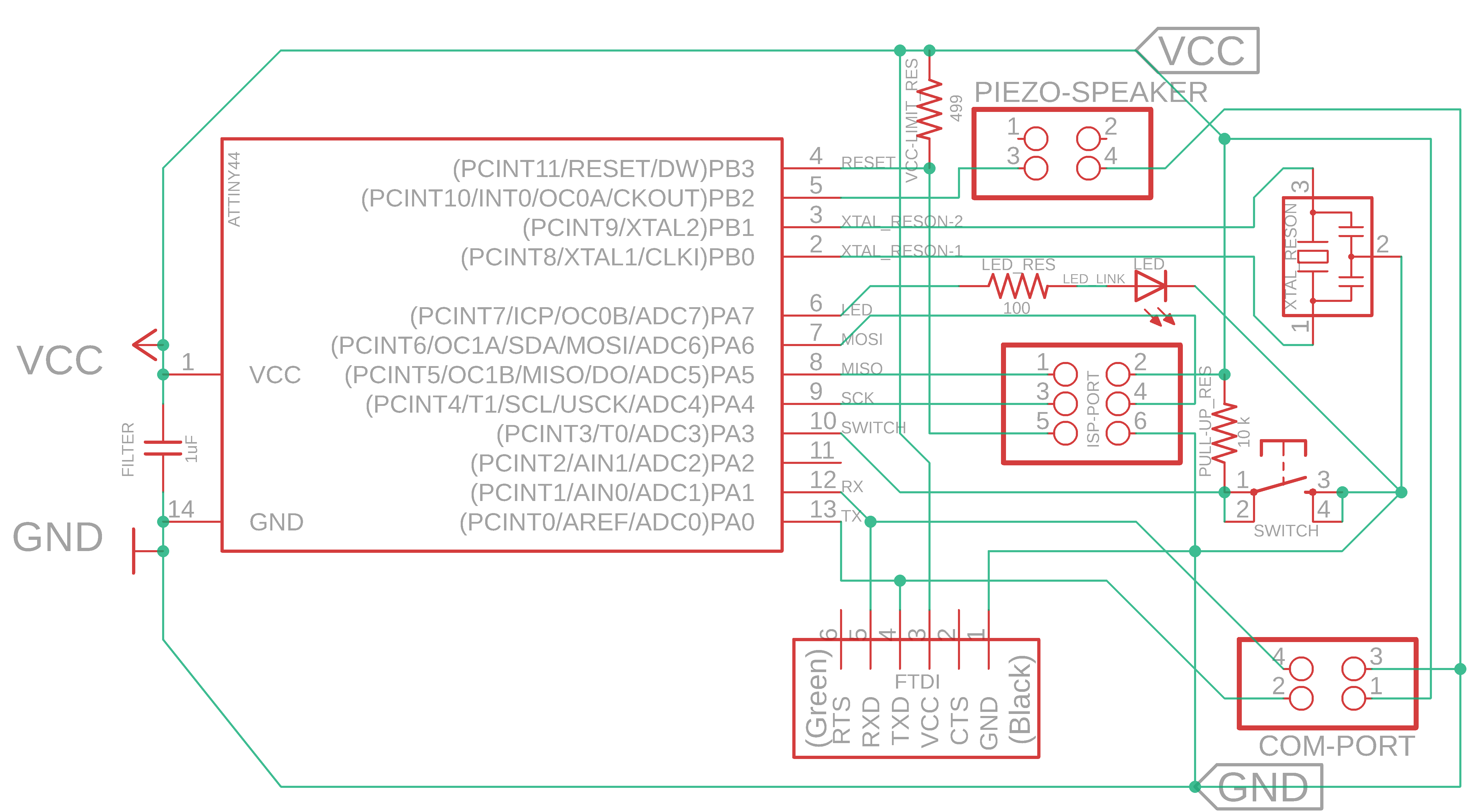
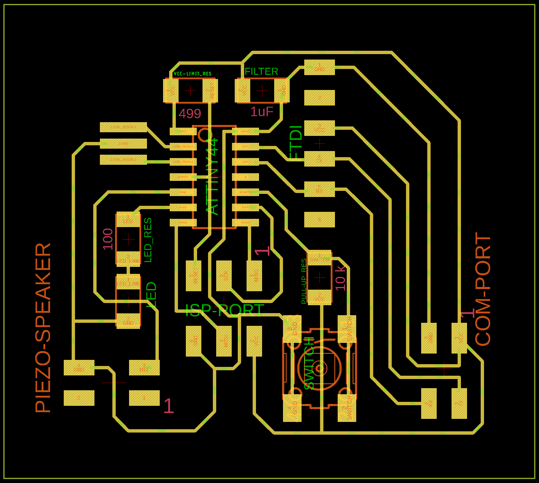
For a better speaker option, I had to add to that board another branch of traces and components. For that purpose, I started drawing the circuit from Neil’s example reference thinking in add that branch in another moment.
This was my attemp to draw the Neil’s board schematics, but using an ATtiny44 microcontroller that will allow to add the hello-world branch on the other free pins:

Used components: ATtiny44 |
To accomplish this goal, I have to dive into coding much more than just the first example, something in what I’m so interested pointing to my final project, but having no time on this week. It is pending…
Finally, after testing the example code on my hello-world board, I decided to reach the first target described using that board and redrawing the necessary changes to add the speaker and the 2x2 communication port.
At this point, I found and ‘issue’ with the speaker footprints because I used for them the 2x2 pin header one. The speaker only needs 2 footprints, one for the pin 5 and another to the GND.
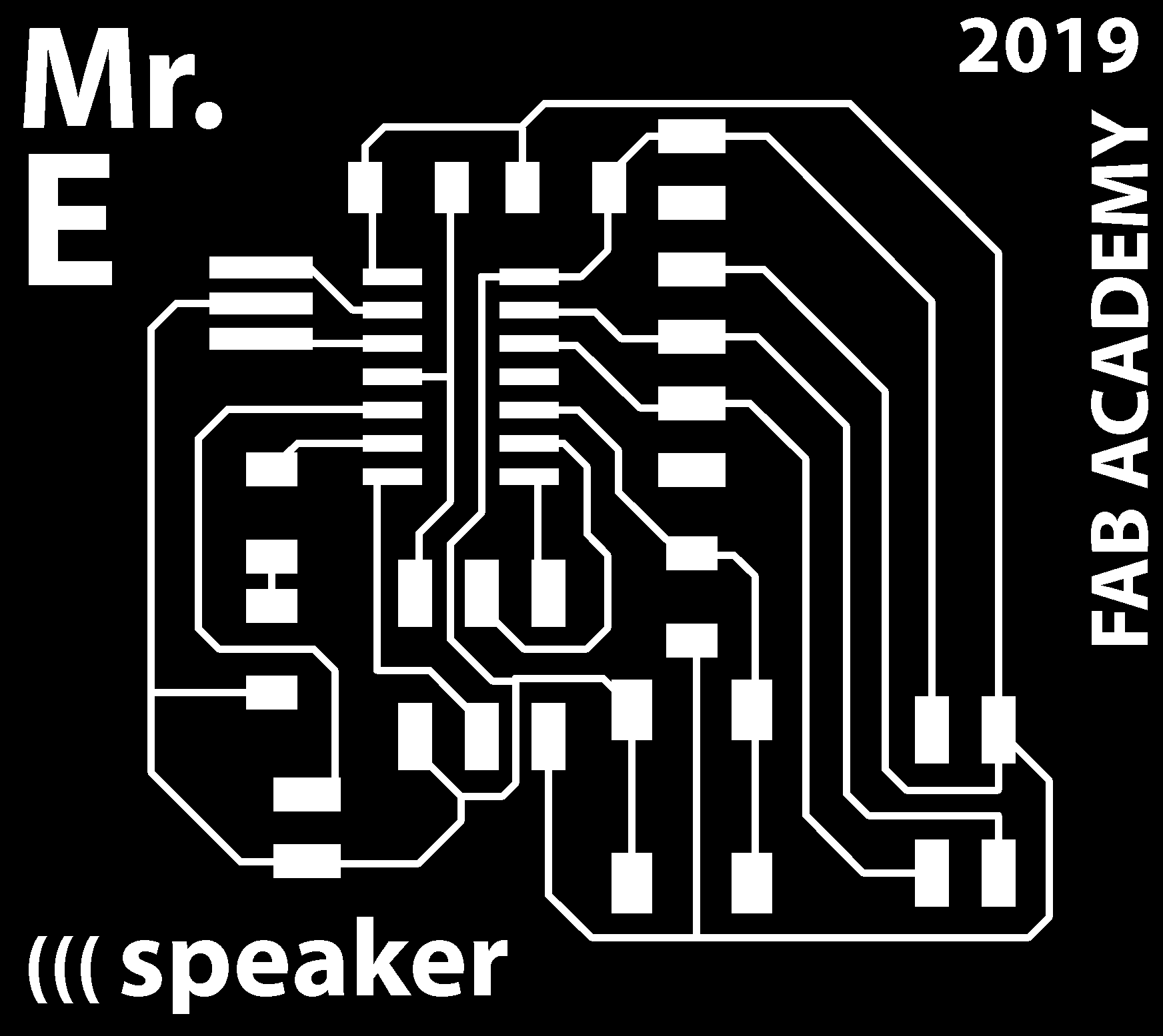
So, I had to ‘make-up’ this on Photoshop. Also, I customized the board at this step.
Board production
I used the Roland monoFAB SRM-20 to trace and cut my board with 1/64’‘ and 1/32’‘ mills. The .rml files were generated from fabmodules.org:
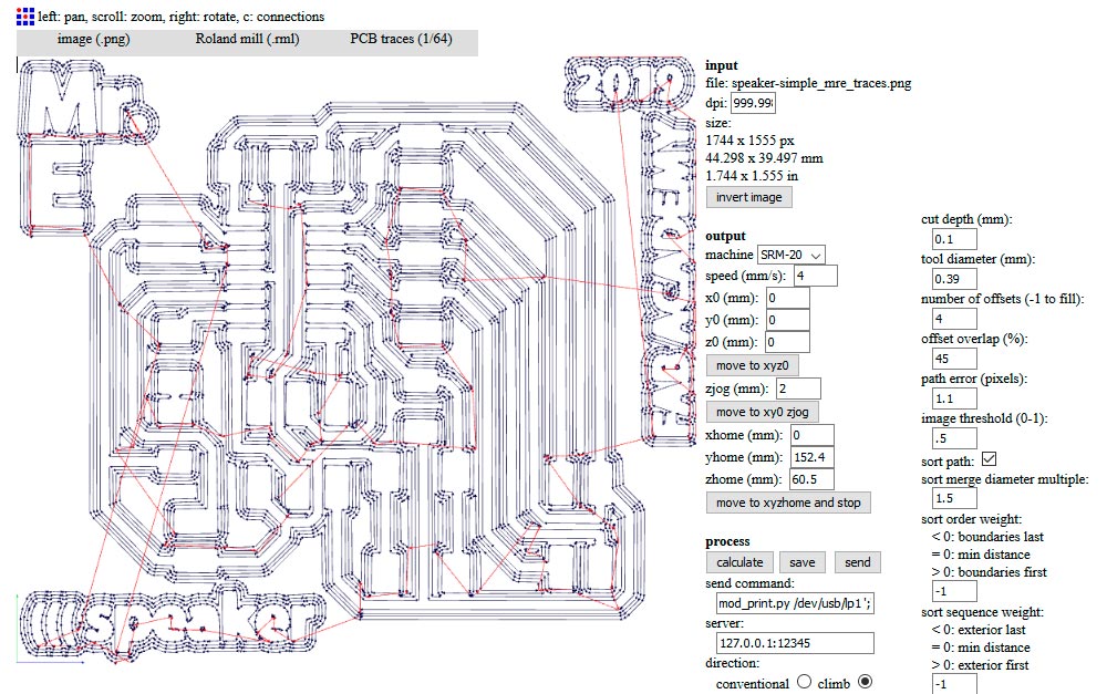
Notice the SPEED | TOOL_DIAMETER and OFFSET_OVERLAP values
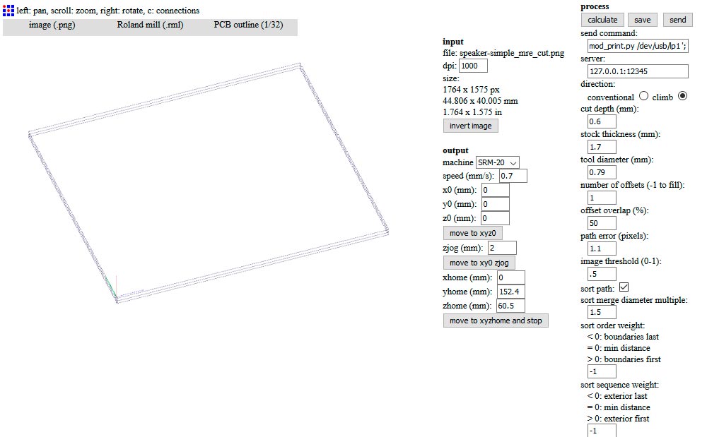
Notice the SPEED and TOOL_DIAMETER values
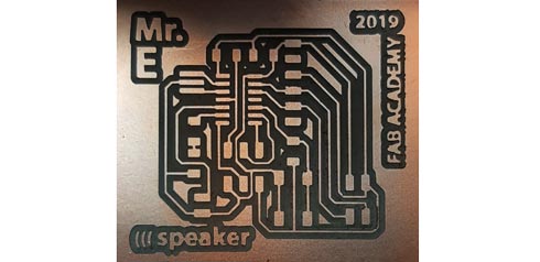
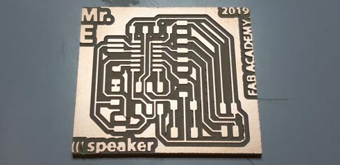
And this was the final tracing job:
I also decided to create an enclosure for the speaker. This process helps the sound from the acoustics to be reinforced, specially on low frequencies. I used makeabox.io site to fastly create my box. Then, I modified it in Illustrator to align parts acording to my 3mm MDF material, and to add the speaker hole and the bass-reflex ports (Note: This design is just an aproximation, and it is not calculated like needed):
Source > Thiele - Small Analysis of Loudspeaker Enclosures
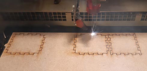
Kerf calculation made on week05 was very useful to make the enclosure parts to fit perfectly, specially on sound/acoustics topic in which the non-presence of air between the joint it’s something necessary.
Notice that the to small holes on the front part are not for the wires, they are ports for the bass frequencies.
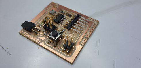
The board was fine and ready to add the next components:
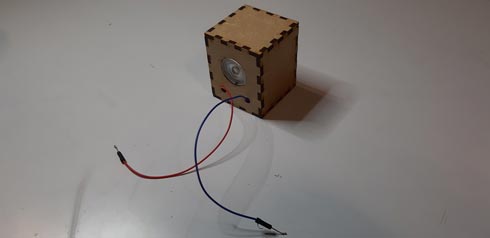
And this is the result with components added:

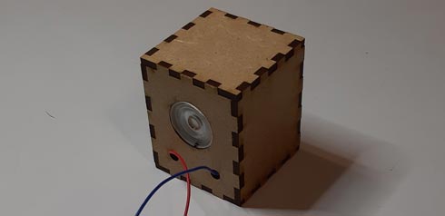
And this would be the final result…
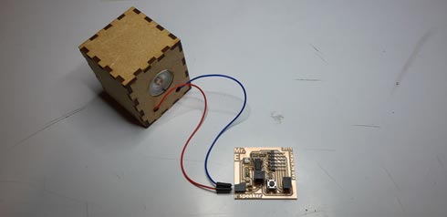
… working with the FTDI
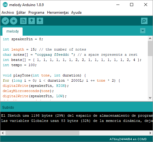
Programming
I used the Emma Parechi Arduino code to test the speaker, and it worked:
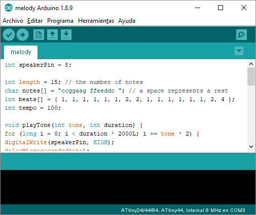
int speakerPin = 9;

int length = 15; // the number of notes
char notes[] = "ccggaagffeeddc "; // a space represents a rest
int beats[] = { 1, 1, 1, 1, 1, 1, 2, 1, 1, 1, 1, 1, 1, 2, 4 };
int tempo = 300;

void playTone(int tone, int duration) {
for (long i = 0; i < duration * 1000L; i += tone * 2) {
digitalWrite(speakerPin, HIGH);
delayMicroseconds(tone);
digitalWrite(speakerPin, LOW);
delayMicroseconds(tone);
}
}

void playNote(char note, int duration) {
char names[] = { 'c', 'd', 'e', 'f', 'g', 'a', 'b', 'C' };
int tones[] = { 1915, 1700, 1519, 1432, 1275, 1136, 1014, 956 };

// play the tone corresponding to the note name
for (int i = 0; i < 8; i++) {
if (names[i] == note) {
playTone(tones[i], duration);
}
}
}

void setup() {
pinMode(speakerPin, OUTPUT);
}

void loop() {
for (int i = 0; i < length; i++) {
if (notes[i] == ' ') {
delay(beats[i] * tempo); // rest
} else {
playNote(notes[i], beats[i] * tempo);
}

// pause between notes
delay(tempo / 2);
}
}
I changed the default speakerPin to the ATtiny44, following this Fab Academy table:
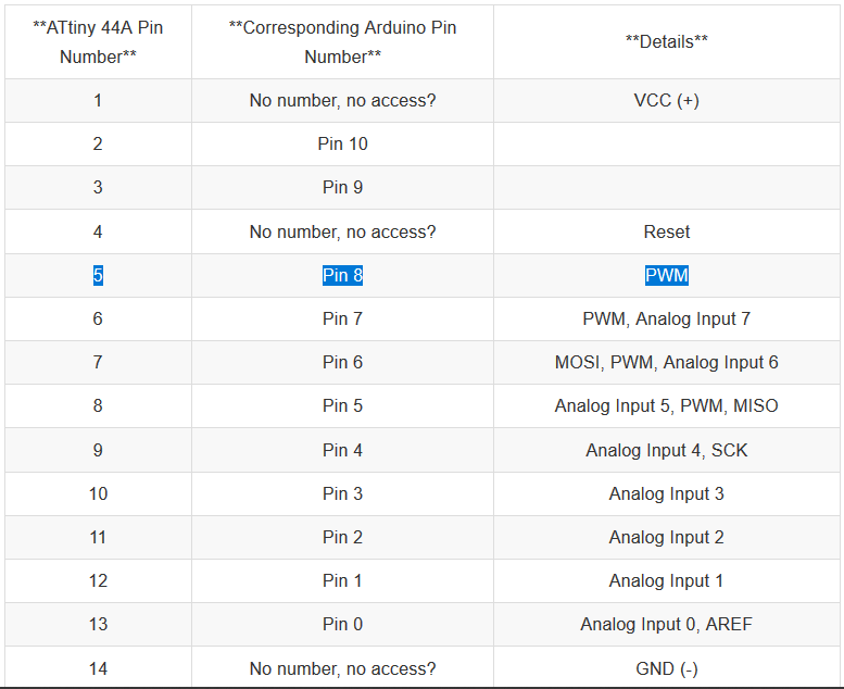
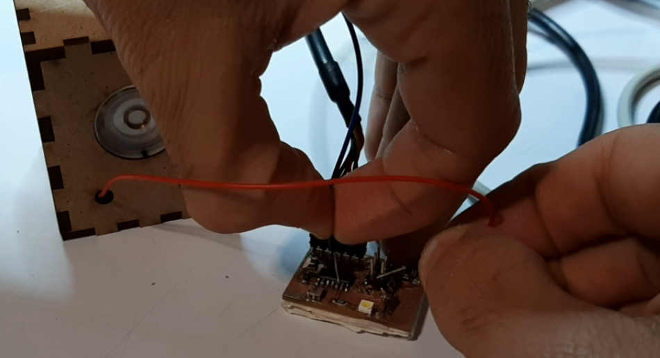
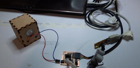
Here I show how the speaker works with my previous board in this test process:
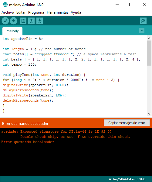
When programming my speaker-button-led-com board, I used my FABtinyISP and Arduino software to burn the bootloader and to upload the code to the speaker board.
And… it failed on the bootloader process…
To discard/find problems, I decided to:
-
disconnect FTDI from the speaker_board > reported error:
>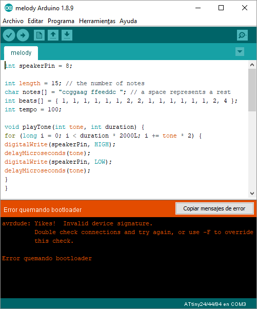
-
disconnect 6 pin header from the speaker_board > reported error:
>
So I had to double-check the connections with multimeter to find where the problem could be…
After reviewing the board, I found that… I forgot to weld the 8th pin at ATtiny44!
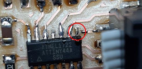
Once weld, the bootloader process and the code uploading were succesful at the first attemp!
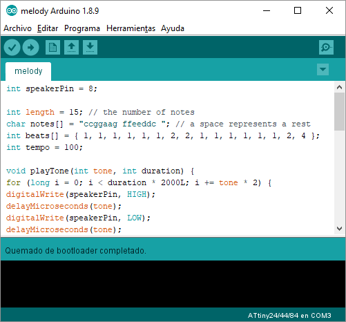
So… this is the board working at a basic stage:
I now also can try to combine this code with the button one in order to start the sound, turn on the LED and output serial info by pressing down the button once, and the inverse process by pressing the button again.
<!–
final code
–> Ans it remains to do my own melody…
Files
- Eagle > (schematics/board)
- .png > (traces/cut)
- Code > (Arduino)