14. Networking and communications
This week I worked on 1 main task on Networking and communications in order to demonstrate workflows used in network design and to implement and interpret networking protocols. These were the assignments:
-
Group assignment:
Send a message between two projects (assignments made by different students)
(Follow this link to see the group assignment) -
Individual assignment:
Design, build, and connect wired or wireless node(s) with network or bus addresses.
SUMMARY
Have you?
-
1. Described your project using words/images/diagrams/schematic screenshots > DONE
-
2. Explained the programming process/es you used > DONE
-
3. Outlined problems and how you fixed them > DONE
-
4. Included design files (or linked to where they are located) and original code > DONE
Pending tasks
- 1. I would like to try on sound field
ASSIGNMENT
Individual - Communicate 2 boards (processes)
Processes
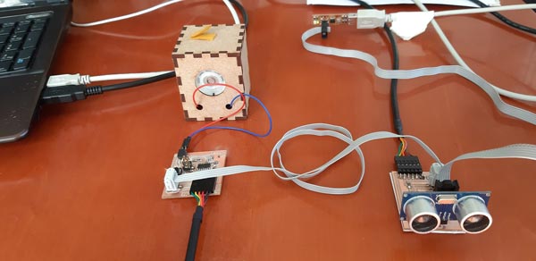
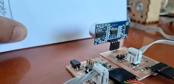
To communicate processes I used my past two input and output boards:
The idea is to control the output device (speaker-LED) with the input one (sonar)
Process
My first idea was to make a type of Theremin system, where the distances tracked by the sonar could be used to modifiy the sound frequency made by the speaker:

I used these references to try this system:
- Tone Output Using An Arduino
- Un (molesto) theremin con Arduino y un HC-SR04
- Arduino theremin - Theremino!
- Ultrasonic Theremin
- Midi Theremin with arduino and ultrasonic sensor HC-SR04
- ATTiny-Theremin
- Final project - Mini SoundBot
Example video (Source):
For this purpose I had to made some modifications:
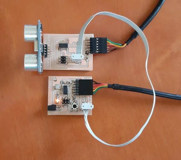
-
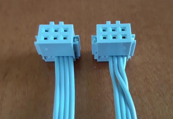
Communication wire (ribbon)
In both boards I’m using a 2x2 pin header, which pins are connected to GND, VCC, TX and RX (Attiny44) pins
As TX must send the signal to RX, and considering that the 2x2 pin header footprints and traces are not modified on the boards, I had to swap 1 and 3 wires on the ribbon to make a cross link: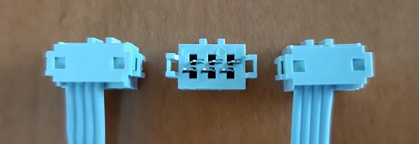
-
Codes
The idea with the code is to use the serialPrint library to send the sonar results to serial on the input device, and to receive them by the same way into the output device.
So I had to divide the code:
INPUT CODE (SONAR)
    #include <SoftwareSerial.h>
    SoftwareSerial mySerial(0, 1);

    const int trigPin = 10;
    const int echoPin = 9;

    // define variables
    long duration;
    int distance;

    //MR.E >  define initial setup
    void setup() {
      pinMode(trigPin, OUTPUT); // Sets the trigPin as an Output
      pinMode(echoPin, INPUT); // Sets the echoPin as an Input
      mySerial.begin(9600); // Starts the serial communication
    }

    //MR.E > define loop
    void loop() {
    // Clears the trigPin
    digitalWrite(trigPin, LOW);
    delayMicroseconds(2);
    // Sets the trigPin on HIGH state for 10 micro seconds
    digitalWrite(trigPin, HIGH);
    delayMicroseconds(10);
    digitalWrite(trigPin, LOW);
    // Reads the echoPin, returns the sound wave travel time in microseconds
    duration = pulseIn(echoPin, HIGH);
    // Calculating the distance
    distance = duration * 0.034 / 2; // Sends
    // digitalWrite(TXpin, distance); // Sends distance through TXpin

    //we write distance to the serial port
    mySerial.write(distance);

    // Prints the distance on the Serial Monitor
    mySerial.print("Distance: cm");
    mySerial.println(distance);
  }
OUTPUT CODE (SPEAKER)
    #include <SoftwareSerial.h>
    SoftwareSerial mySerial(0, 1);
    int speakerPin = 8;
    int distancia;
    float freqRad;
    int tono;
    #define MIN_DISTANCIA 30

    void setup() {
      pinMode(speakerPin, OUTPUT);
      mySerial.begin(9600);
    }

    void loop() {
      digitalWrite(speakerPin, HIGH);
      if(mySerial.available()){
        distancia = mySerial.read();
        if (distancia < MIN_DISTANCIA) {
          freqRad = sin(distancia*(3.14/180));
          tono = 2000+(int(freqRad*1000));
          tone(speakerPin, tono, 500);
        }
      }
    }
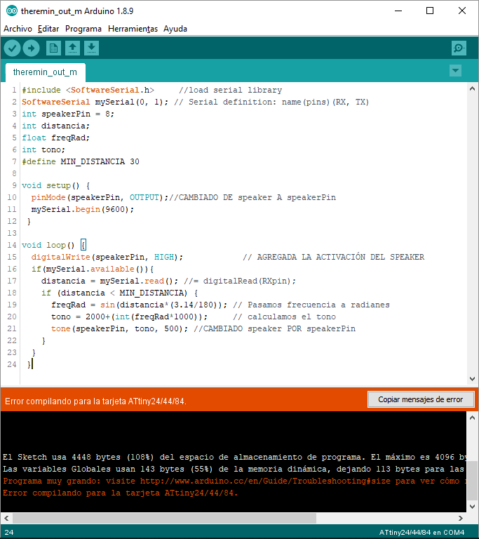
At this point, I tried with the wire and codes and I found an issue: the output code is bigger than 4096 bytes and does not fit into the ATTtiny44 microcontroller.
Specifically the line
tone(speakerPin, tono, 500);which cost is more than 2 kB
I reminded what prof. Neil told about the use of libraries, but, in order to accomplis the target (and the assignment), I used the LED into the output board to response to the input signal:
OUTPUT CODE (LED)
  #include <SoftwareSerial.h>     //load serial library
    SoftwareSerial mySerial(0, 1); // Serial definition: name(pins)(RX, TX)

    int led = 7;           // the PWM pin the LED is attached to
    int brightness;

    void setup() {
      pinMode(led, OUTPUT);
      mySerial.begin(9600);
    }

    void loop() {
      if(mySerial.available()){
          brightness = map(mySerial.read(), 0, 2000, 0, 255);
          analogWrite(led, brightness);
      }
    }
This sonar controlled LED test was successful.
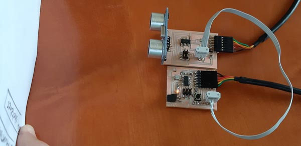
Now I have to find a way to use work in sound field, probably by changing the microcontroller because of the dificulty to program in pure C code. I saw that other microcontrollers, like ATtiny85, host 8 kB, but have another limitations, like the number of pins to operate with them.
UPDATE:
As the idea was to address the networking to an specific device, this is the way made by software:
SONAR CONTROLLER
#include <SoftwareSerial.h>
SoftwareSerial mySerial(0, 1);

#define address_1 1

const int trigPin = 10;
const int echoPin = 9;
const int TXpin = 0;

long duration;
int distance;

void setup() {
  pinMode(trigPin, OUTPUT); // Sets the trigPin as an Output
  pinMode(TXpin, OUTPUT); // Sets the TXpin as an Output
  pinMode(echoPin, INPUT); // Sets the echoPin as an Input
  mySerial.begin(9600); // Starts the serial communication
}

void loop() {


    digitalWrite(trigPin, LOW);
    delayMicroseconds(2);
    digitalWrite(trigPin, HIGH);
    delayMicroseconds(10);
    digitalWrite(trigPin, LOW);
    duration = pulseIn(echoPin, HIGH);
    distance = duration * 0.034 / 2; // Sends
    digitalWrite(TXpin, distance); // Sends distance through TXpin
    mySerial.print("Distance: cm"); //MR.E > Added "cm"
//    mySerial.println(distance);
    mySerial.write(address_1);

}
CONTROLLED LED
#include <SoftwareSerial.h>     //load serial library
SoftwareSerial mySerial(0, 1); // Serial definition: name(pins)(RX, TX)

#define led 7           // the PWM pin the LED is attached to
int brightness;

#define address_1 1
int bytein = 0;   // for incoming serial data

void setup() {
  pinMode(led, OUTPUT);
  mySerial.begin(9600);
}

void loop() {
  if (mySerial.available() >= 1) {
    int addressByte = mySerial.read();
    if (addressByte == address_1); {
      brightness = map(mySerial.read(), 0, 2000, 0, 255);
      analogWrite(led, brightness);
    }
  }
}
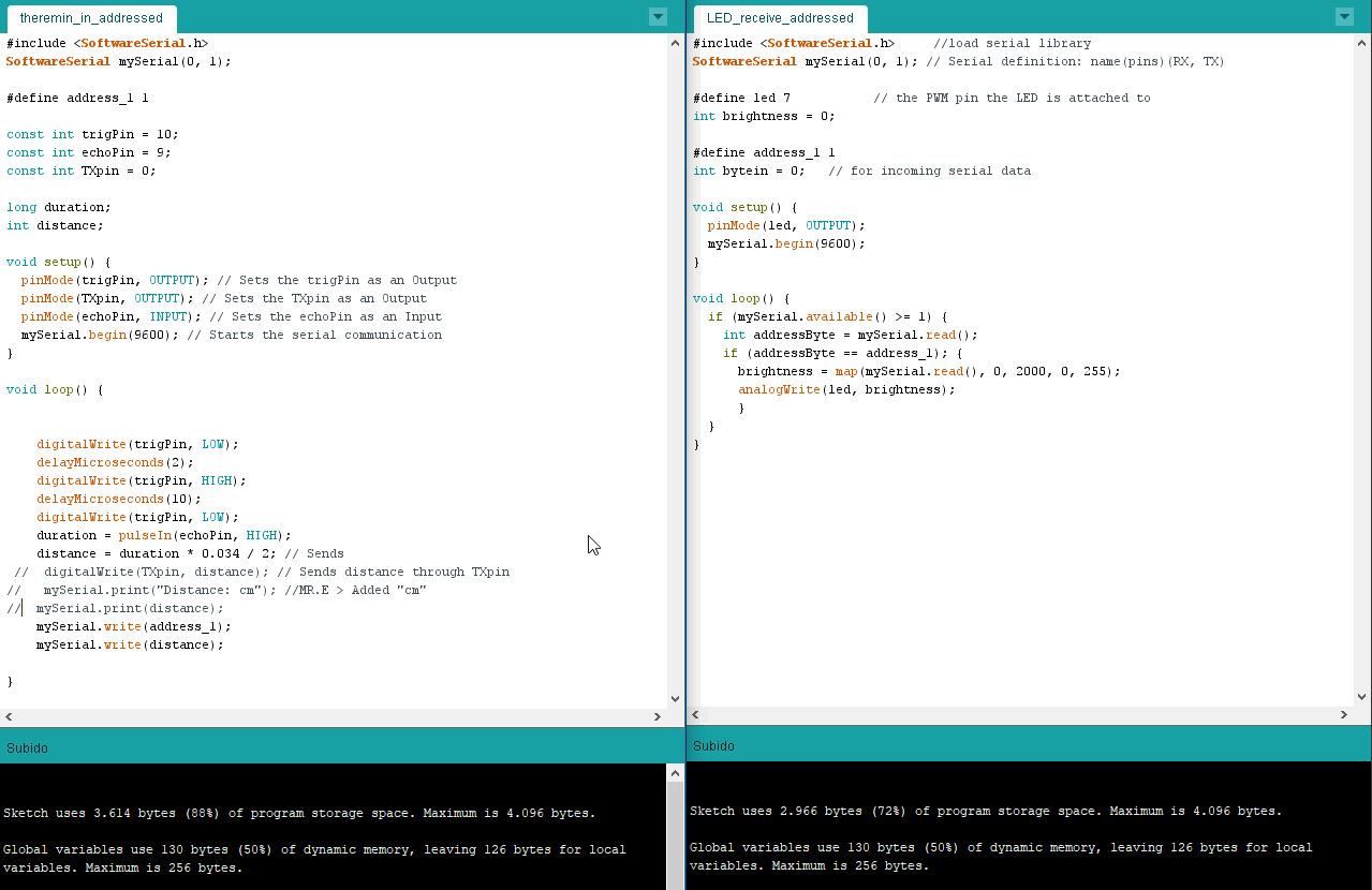
These codes were doing the address part, but the message still be needed to be sent from A to B, so these are the final codes (and a capture) and the video with the boards working:
SONAR CONTROLLER FINAL
#include <SoftwareSerial.h>
SoftwareSerial mySerial(0, 1);

#define address_1 1

const int trigPin = 10;
const int echoPin = 9;
const int TXpin = 0;

long duration;
int distance;

void setup() {
  pinMode(trigPin, OUTPUT); // Sets the trigPin as an Output
  pinMode(TXpin, OUTPUT); // Sets the TXpin as an Output
  pinMode(echoPin, INPUT); // Sets the echoPin as an Input
  mySerial.begin(9600); // Starts the serial communication
}

void loop() {


    digitalWrite(trigPin, LOW);
    delayMicroseconds(2);
    digitalWrite(trigPin, HIGH);
    delayMicroseconds(10);
    digitalWrite(trigPin, LOW);
    duration = pulseIn(echoPin, HIGH);
    distance = duration * 0.034 / 2;
    mySerial.write(address_1);
    mySerial.write(distance);

}
CONTROLLED LED FINAL (digitalWrite)
#include <SoftwareSerial.h>     //load serial library
SoftwareSerial mySerial(0, 1); // Serial definition: name(pins)(RX, TX)

#define led 7           // the PWM pin the LED is attached to
int brightness;
int addressByte;

#define address_1 1

int bytein = 0;   // for incoming serial data

void setup() {
  pinMode(led, OUTPUT);
  mySerial.begin(9600);
}

void loop() {
  if (mySerial.available() >= 0) {
    addressByte = mySerial.read();
    if (addressByte == address_1); {
      brightness = map(mySerial.read(), 0, 2000, 0, 255);
      digitalWrite(led, brightness);
      }
  }
}
Video demonstration:
This is the target device code with the LED triggered by analogWrite instead of digitalWrite:
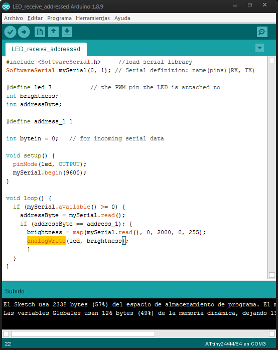
CONTROLLED LED FINAL (analogWrite)
#include <SoftwareSerial.h>     //load serial library
SoftwareSerial mySerial(0, 1); // Serial definition: name(pins)(RX, TX)

#define led 7           // the PWM pin the LED is attached to
int brightness;
int addressByte;

#define address_1 1

int bytein = 0;   // for incoming serial data

void setup() {
  pinMode(led, OUTPUT);
  mySerial.begin(9600);
}

void loop() {
  if (mySerial.available() >= 0) {
    addressByte = mySerial.read();
    if (addressByte == address_1); {
      brightness = map(mySerial.read(), 0, 2000, 0, 255);
      analogWrite(led, brightness);
      }
  }
}
And the video demonstration:
Files
- Codes > (Arduino)
- Codes > (Arduino (addressed))