16. Interface and application programming
This week I worked on 1 task refered to Interface and application programming in order to ‘interpret and implement design and programming protocols to create a Graphic User Interface (GUI).’.
These were the assignments:
-
Group assignment:
Compare as many tool options as possible.
(Follow this link to see the group assignment) -
Individual assignment:
Write an application that interfaces with an input &/or output device that you made.
SUMMARY
Have you?
-
1. Described your process using words/images/screenshots > DONE
-
2. Explained the GUI that you made and how you did it > DONE
-
3. Outlined problems and how you fixed them > DONE
-
4. Included original code (or a screenshot of the app code if that’s not possible) > DONE
Pending tasks
- 1. I would like to try the ControlP5 interface to output
ASSIGNMENT | Create a GUI
Starting
I started this week assignment by reading these 2 tutorials:
As told by Prof. Neil during the class “… Python allows you to split your program into modules that can be reused in other Python programs. It comes with a large collection of standard modules that you can use as the basis of your programs — or as examples to start learning to program in Python. Some of these modules provide things like file I/O, system calls, sockets, and even interfaces to graphical user interface toolkits like Tk.“
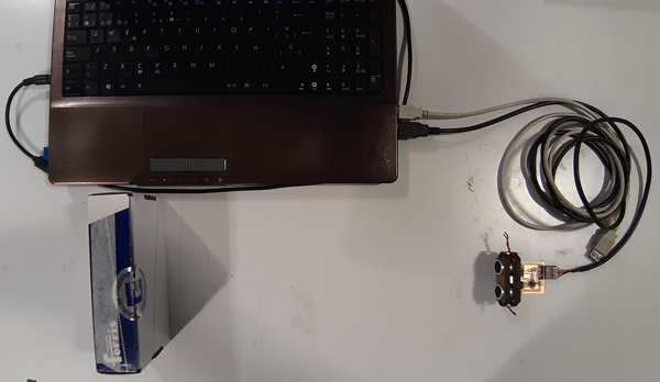
As a general idea, I wanted to try my input (sonar) and output (speaker) boards in interaction with the interface as this way:
- Input -> INTERFACE
- INTERFACE -> Output
Input to interface process
On this process I had to:
- upload to the sensor board (sonar) the sonar code needed by the ultrasonic device to work and give echo results that finally are sended by serial pin/port.
-
add a code for the serial communication, indicating the pin and the port, with the help of the
processing.seriallibrary.Sensor + Serial code
        #include <SoftwareSerial.h>
        SoftwareSerial mySerial(0, 1);
        const int trigPin = 10;
        const int echoPin = 9;
        long duration;
        int val;
        void setup() {
        pinMode(trigPin, OUTPUT);
        pinMode(echoPin, INPUT);
        mySerial.begin(9600);
        }
        void loop() {
        digitalWrite(trigPin, LOW);
        delayMicroseconds(2);
        digitalWrite(trigPin, HIGH);
        delayMicroseconds(10);
        digitalWrite(trigPin, LOW);
        duration = pulseIn(echoPin, HIGH);
        val = duration * 0.034 / 2;
        mySerial.println(val);
        }
Then, I tried with these softwares:
-
The idea with these exercises was to control graphics (interface) with the sensor interactivity. I used the following commands to work on the interface development:
void drawrefers to thevoid loopfunctionmapto translate input values to a preffered theresholdlerpto transport objects with vector principlesrotateto rotate objects- Graphics:
PImageto create a new image variableloadImageto load a local and remote imagesimageModeto set up the image originimageto set up the image position and dimensionssizeto set up the interface dimensionswidthandheightrefers to size dimensionsbackgroundto to set up the canvasrectto create a rectangle and setup its position and dimensionsellipseto create an ellipse and setup its position and dimensionstintto color objectsellipseto create an ellipse and setup its position and dimensions
cursorandnoCursorto set up the cursor visibilitypushMatrixandpopMatrixto create a matrix than controls temporally the whole interface
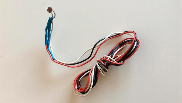
Previously to the sonar interaction, I tried my Processing code with a photo-resistor connected to an Arduino:
First, here it is showed how the graphics begin to work with the sensor interaction: when the distance is higher than 30 cm, the object is moved randomly on the canvas:
The object is animated in position and scale according to the different values of the sensor (sonar distances)
Secondly, I’m playing with the
lerpcommand, specifically with the variation speed (in-space displacement), testing it with the highest and the lowest values:This is the lowest speed: 0.01 value
This is the highest speed: 1 value
Finally, I tried the
rotatecommand, generating spiral graphics from movements and rotations of an object from the center of the canvas:
These are the codes I used:
lerp
import processing.serial.*;

PImage guybrush;
PImage melee;
float rotar;
float scale;
float speed;
float origenx;
float origeny;
float destinox;
float destinoy;
boolean flag=false;

float val;
Serial myPort;

void setup() {

  myPort = new Serial(this, Serial.list()[0], 9600);
  myPort.bufferUntil('\n');
  size(640, 400);
  background(0);
  guybrush=loadImage("guybrush.png");
  melee=loadImage("https://www.hejorama.com/wp/wp-content/uploads/2012/10/Melee_Island_Map.jpg");
  cursor(CROSS);
  // noCursor();
  origenx=0;
  origeny=0;
  destinox=random(width);
  destinoy=random(height);
}

void draw() {
  imageMode(CENTER);
  //tint(255,100); //colorea objetos
  scale=map(val, 0, 400, 0, guybrush.width);
  speed=map(val, 0, width, 0, 0);
  image(melee, width/2, height/2, melee.width, melee.height);
  pushMatrix(); // opens the matrix
  image(guybrush, origenx, origeny, guybrush.width/scale*2, guybrush.height/scale*2);
  if (val<=30) {
    flag=true;
    translate(guybrush.width/2, guybrush.height/2);
  rotate(rotar); //(0.1 to 1 is the increment of the rotation)
 rotar = rotar+0.05;
  } else {flag=false;}
    if (flag==true) {
    origenx = lerp(origenx, destinox, 0.05);
    origeny = lerp(origeny, destinoy, 0.05);
  }
  if (int(origenx)==int(destinox)){
  flag=false;
  destinox=random(width);
  destinoy=random(height);
  }
  popMatrix();//closes the matrix
  fill(0, 20);
  rect(0, 0, width, height);
  println(val);
}

void serialEvent(Serial myPort) {
  String inString = myPort.readStringUntil('\n');
  if (inString != null) {
    inString = trim(inString);
    float[] values = float(split(inString, ","));
    if (values.length >=1) {
      val = values[0];
    }
  }
}
rotate
import processing.serial.*;

PImage foto;
float rotar;
float val;
Serial myPort;

void setup(){
  myPort = new Serial(this, Serial.list()[0], 9600);
  myPort.bufferUntil('\n');
  size(600,600);
  background(0);
  foto=loadImage("guybrush.png");
  cursor(CROSS);
  noCursor();
  }

  void draw(){
  imageMode(CENTER);
  //tint(255,100); //colorea objetos
  pushMatrix();//opens a change related to the canvas to an object
    translate(width/2, height/2);//moves center of coordinates
    rotate(rotar); //(0.1 to 1 is the increment of the rotation)
    image(foto, val*6, val*6, foto.width/2, foto.height/2);
  popMatrix();//closes the matrix
  rotar = rotar+1;
  println(val);
  }

  void serialEvent(Serial myPort) {
  String inString = myPort.readStringUntil('\n');
  if (inString != null) {
    inString = trim(inString);
    float[] values = float(split(inString, ","));
    if (values.length >=1) {
      val = values[0];
    }
  }
}
-
Pure Data
The idea with this exercise was to control sound with the sensor board (sonar). The first step was to load to the input board the communication with the interface code. The code used for that had to be mixed with the sonar code.
Once the code was loaded on the sensor board, it was the Pure Data interface time.
It’s possible to add many different elements to a workspace in where they will be interconnected to send data between them.
It was necessary to stablish a previous communication flow chain before the sound field flow chain. This was the most embarrassing part, because of the different Pure Data software versions. Basically, it’s necessary to join these elements as shown:
More info here (cskonopka)
Depending on the Pure Data version, some .dll or program files were/were not where they must be.
This example was made on Pd-extended (discontinued) version because the last Miller S. Puckette’s “vanilla” distribution (v. 0.49-1) was not working whencomportelement was added to the workspace (although the program files were on the program folder).The element was not generated fully operative when typing
comportat the time to add a new object.On the other side, the Pd-extended version didn’t have some files on its extra folder… The rare solution was to copy these needed files from the vanilla’s folder to the extended’s one (!!!).
So, ensure to have on %SYSTEM%/%PROGRAMFILES%/pd/extra, at least, these necessary files (not only .pd files, but .dll included):- comport
- sel
- zl
- iem
- fromsymbol
Once the serial communication with sensor was stablished (when clicking
openelement sensor inputs should be shown on anumberbox attached to theunpack-the last element of the chain- output):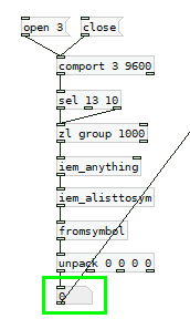
Finally, it was time to play with sound elements with the input values from the sensor. Here is the whole scheme:
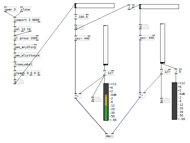
A first generated audio signal is transposed to an equivalent 2 octaves lower new signal. Horizontal sliders control the frequencies and vertical ones control the levels, shown on vumeters.
Here is the sonar sensor working on Pure Data:
Interface to output process (PENDING)
On this process I had to:
- upload to the output board (speaker) the speaker code needed by the speaker device to work and transduct pulses that are received through serial pin/port.
- add a code for the serial communication, indicating the pin and the port, with the help of the
processing.seriallibrary.
Then, I tried with this software:
-
Processing with ControlP5
The idea here was to load atone()code to the speaker board and play sounds with the ControlP5 interface from Processing.These are the codes I used:
CODE GRAPHICS > SPEAKERCODE OUTPUT BOARD