3. Computer Aided design
This week I worked on making some model sketches of what my project may potentially look like when it is finished by using a variety of design software in order to get a rough sketch with which to work with. From the get go, I did not know exactly what kind of shape my device would have, so I decided to take some inspiration. Knowing that my device is to be an ophthalmoscope of some kind, I started by taking inspiration from current designs.
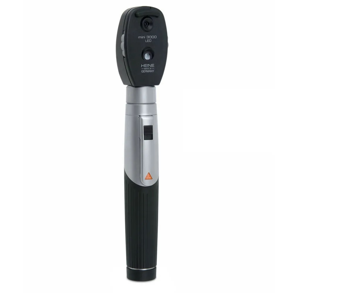
This picture shows the “standard” design used by companies all over the world, and is engineered with the idea of being hand held and used by the optician to perform a somewhat lengthy examination. The device is compromised of a “head” which holds the focusing lenses and a simple rod attached to it used to hold the device in place, as well as to easily manoeuvre it in order to conduct de examination. However my ideal would not need to be manoeuvred, just placed firmly against the eye. Whereas the standard design is very useful for manoeuvring, it makes it a bit harder to secure properly. As such, I figured a gun like shape would suit it better. This type of shape would allow for an easier time when aligning to the eye and as such allow for better pictures to be taken.
Armed with this knowledge, I set out to create a design.
The first software I made use of was Autodesk’s Fusion 360. Fusion 360 is parametric design software: This means that at any given point, the software is generating my object by following a set of instructions in order. The drawing I can see in the screen is not an actual object, but rather a representation of what my object will look like in if the software followed all the instructions. The advantage of parametric design is the ease with which parameters and specifications can be inputted in the software. Furthermore, Fusion 360 allows to work both in 3d as well as 2d. The software is able to generate 3d files such as STL, as well as 2d designs such as DXF
I started with making a very basic pistol shape by simply drawing it out, giving the handle an angle of roughly 7.5 degrees, as this is apparently considered to be a good standard when making this sort of hand held tools.
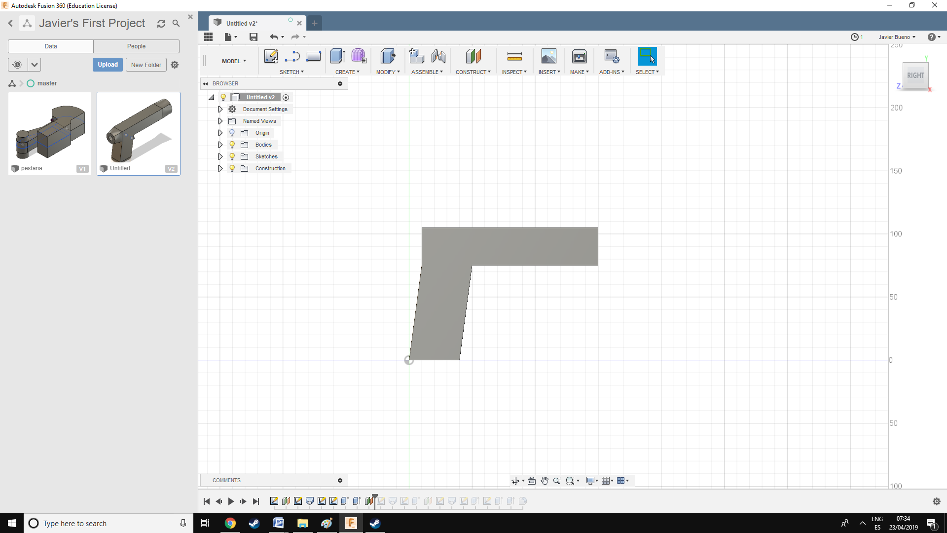
My original idea was to fit the camera device within the “barrel” of the device, and thus line it up with the person’s eye. In order to facilitate this, I thought I would slot in an extension to both sides of the “barrel” which will aid on securing the device to the patients eye whilst taking the picture. While I was at it I rounded off some corners and added a button which would be used to focus and take the actual pictures.
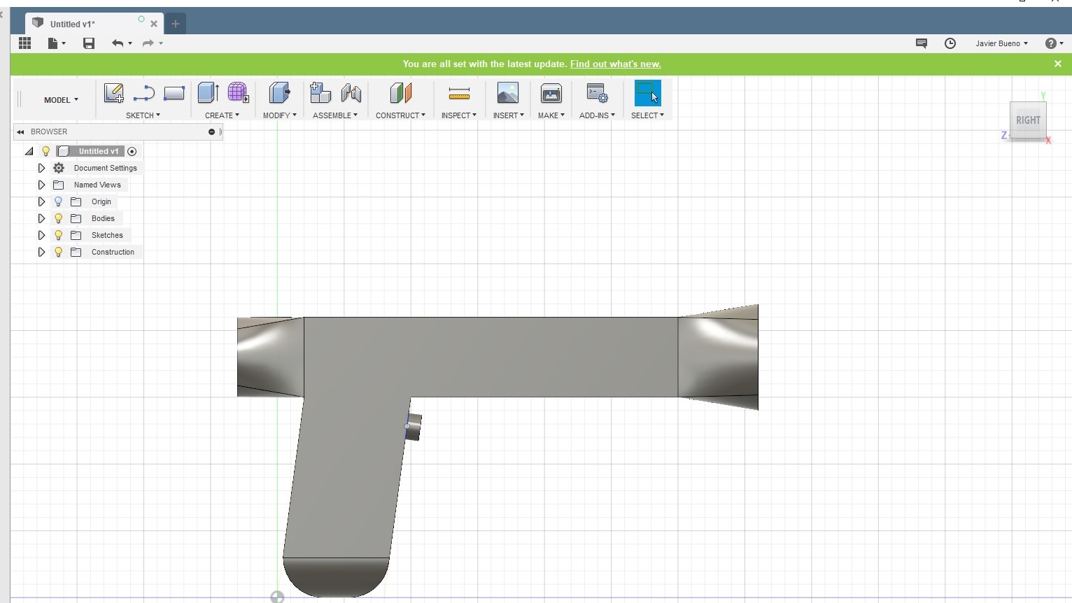
Once that was done as a 2d drawing, I decided to extrude it, thus converting it to 3d drawing I can then export as an STL, or a variety of other design software’s.
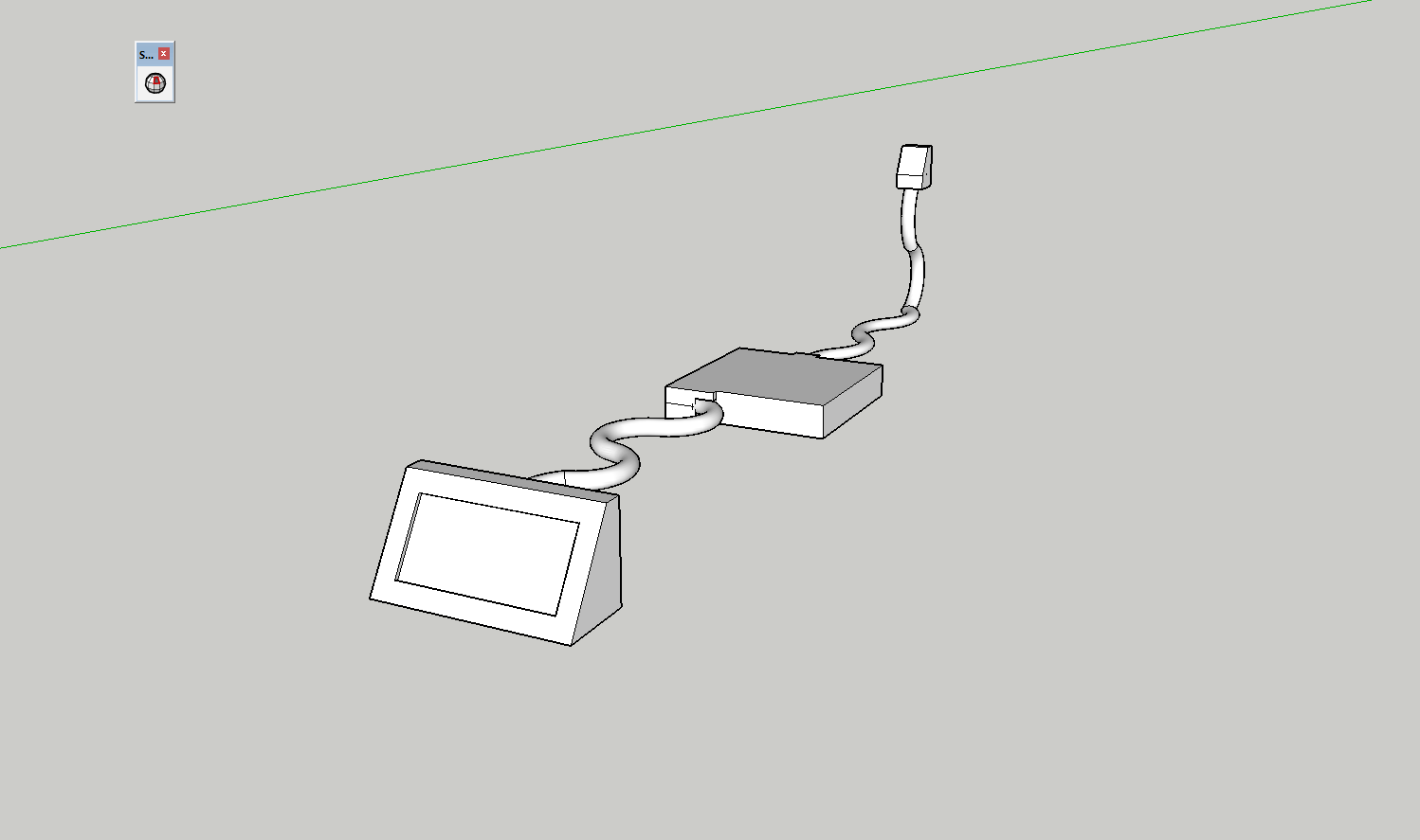
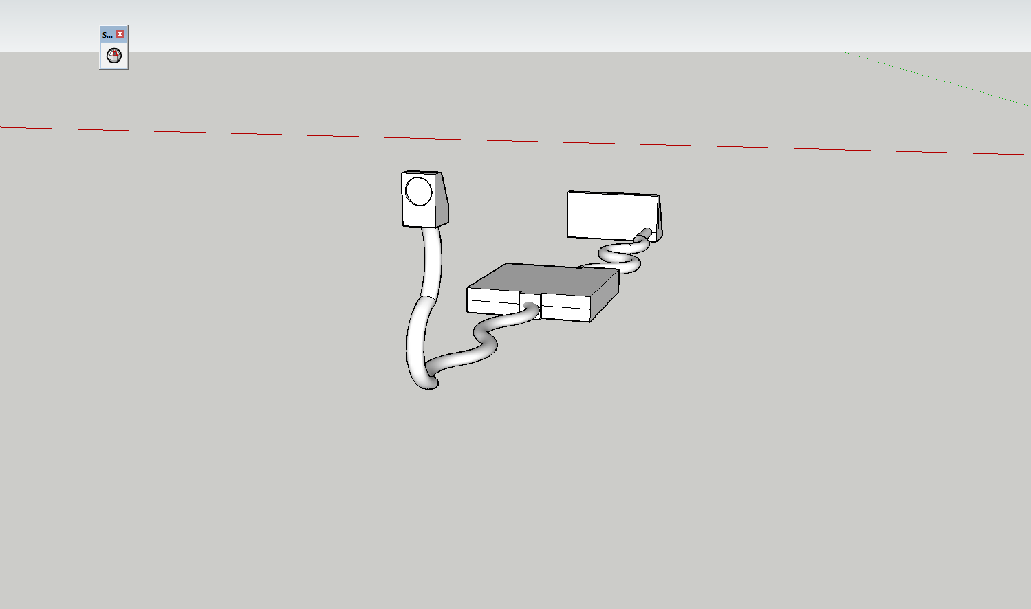
After having done a first sketch on fusion I decided to use second type software to make an alternative design style for the potential final project. This time, I decided I would use Sketchup for the design. Sketchup is a sculpting software, meaning it is different from Fusion 360 (which is parametric) in several important areas. The main difference is that in Fusion 360 the object does not actually exist, it is a product of the various instructions given to the software. On Sketchup on the other hand, the object actually exists. Whenever an object is created in Sketchup the geometry exists, and as such can be acted upon. This means that one simply drag and pull the object around with complete freedom. This means that Sketchup is generally a far more intuitive software to use. Furthermore, unlike Fusion where one is constrained by the tools given, Sketchup can generate virtually any shape imaginable. The downside is that it is virtually impossible to set constrains on design and as such, everything has to be done manually. This means that certain designs will end up taking far more time than in fusion. Furthermore, it also means that Sketchup cannot match the precision and exact measurements that Fusion can achieve. One is not better than the other; rather they are two different tools for different purposes.
Whereas the previous design involved fitting all the equipment on a single compact device in order to take pictures, my other idea was to make the system separate and add an LCD screen.
In order to do this, the processor would need to be in its own case. Then some form of screen would be connected to the CPU. Initially this would have to be done through cable; wireless would be best, but in the spirit of Spiral development it would be far easier to do it with cable first, and then potentially upgrade to wireless in the future.
On the other side there would be the camera. The camera would be also connected to the CPU in order to achieve a live feed to the screen. This would have the advantage of making the camera lightweight and as such easier to manoeuvre. Furthermore the live feed would enable for a more detailed examination compared to simple pictures. Te downside of this configuration would be the extra size and added encumbrance of the machine.