Electronic production
Machine Specifications
For this week I used a Rolan SRM - 20 machine in order to fabricate the boards to be used to manufacture our programmer. The SRM - 20 is a precision tabletop milling machine with the following specs:
-
Work Area: a work area of 20cm by 15cm, with a height of up to 6cm
-
Max Size: The machine is able to equip any tool size up to a maximun of 6mm
-
Spindle Speed: the spindle can rotate up to 7000rpm
-
Mechanical Resolution: The machine has a theoretical perfect resolution of 0.002mm, however practical circumstances such as material used or vibrations can lower this number slightly.
-
Computer OS: The machine operates by connecting up to a computer through a USB cable, the computer in question must have installed Windows 10, 8 or 7 in order to function. Older opearting systems are not supported.
The cutting
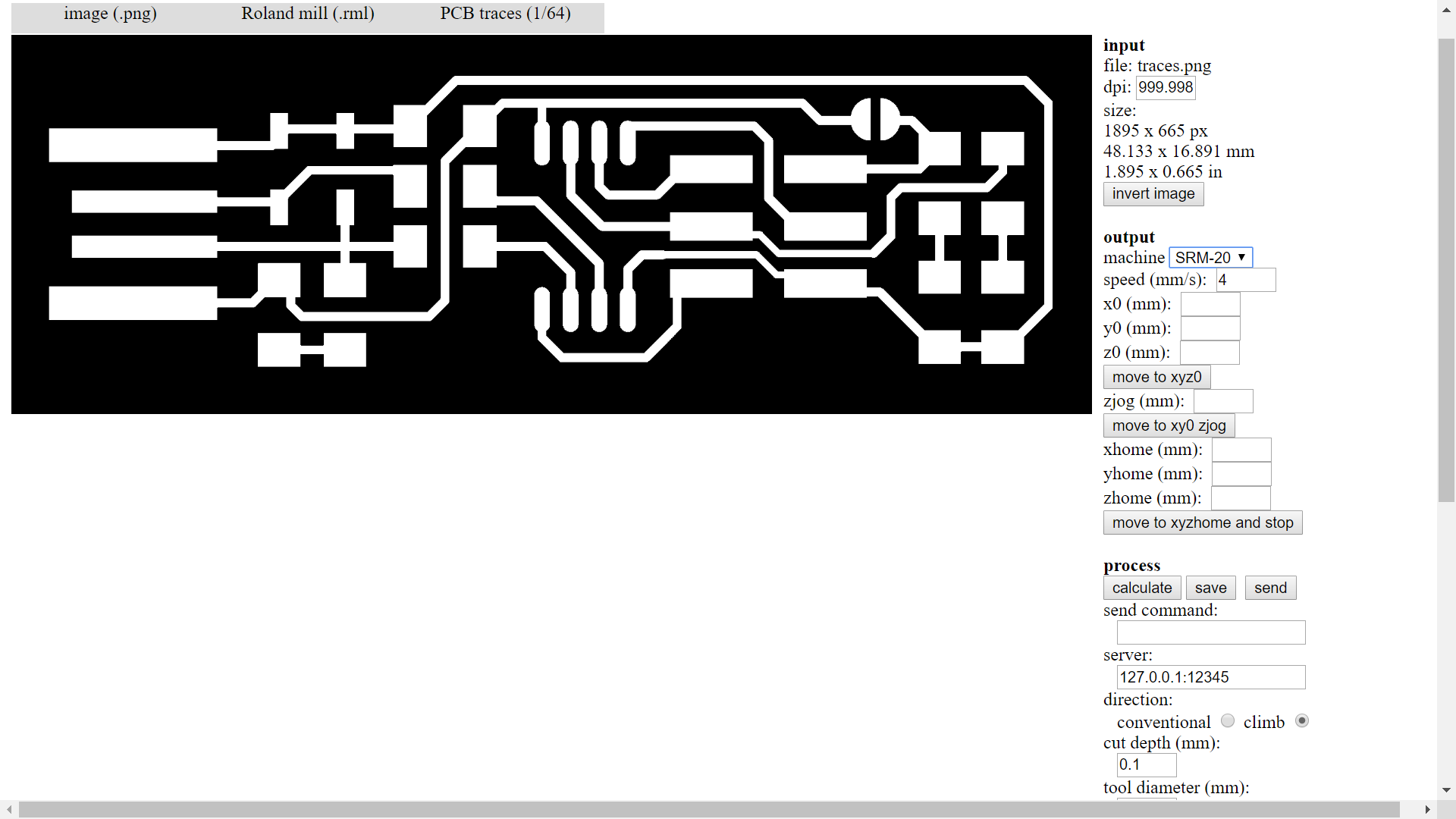
In order to use the mill to cut a circuit I needed to generate the correct gcode for it and feed it to the machine. For this I used Fab Modules with the traces image given in the Fab Lab academy tutorial. I loaded it into the Fab Modules Software and used that to calculate my toolpath for the SRM. Once the toolpath was calculated I proceeded to ready the machine.
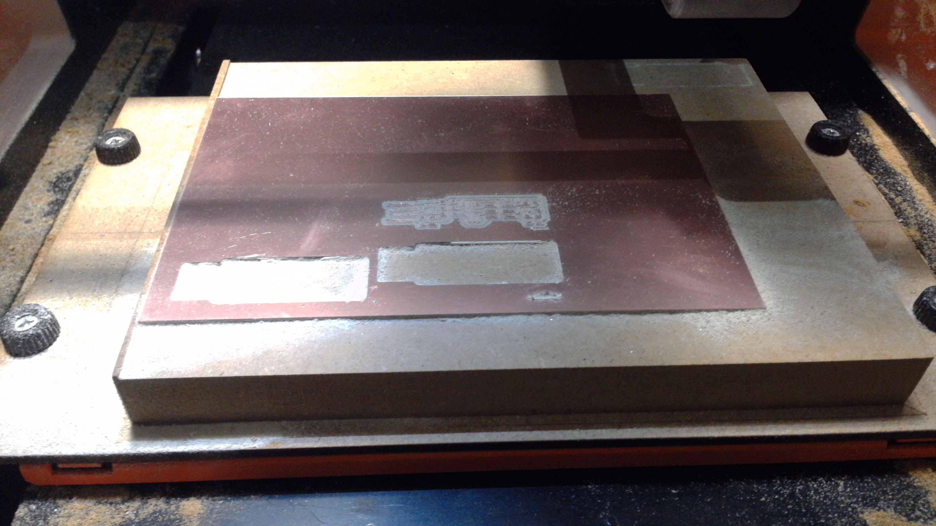
I taped the underside of the board with double sided tape in order to ensure that it was properly secured. Then I set the X, Y and Z of the machine and proceeded to cut.
Note: one of the main problems I encountered when cutting was just how fragile the traces millls are, I broke two over the course of my cuts. Eventually I figured that the main issue was in my not properly leveling the Z by rushing throught it. Once I sat down and spent several minutes properly ensuring the Z calibration was perfect (including making sure that the bed was properly leveled all points) I managed to cut the traces without further issue.
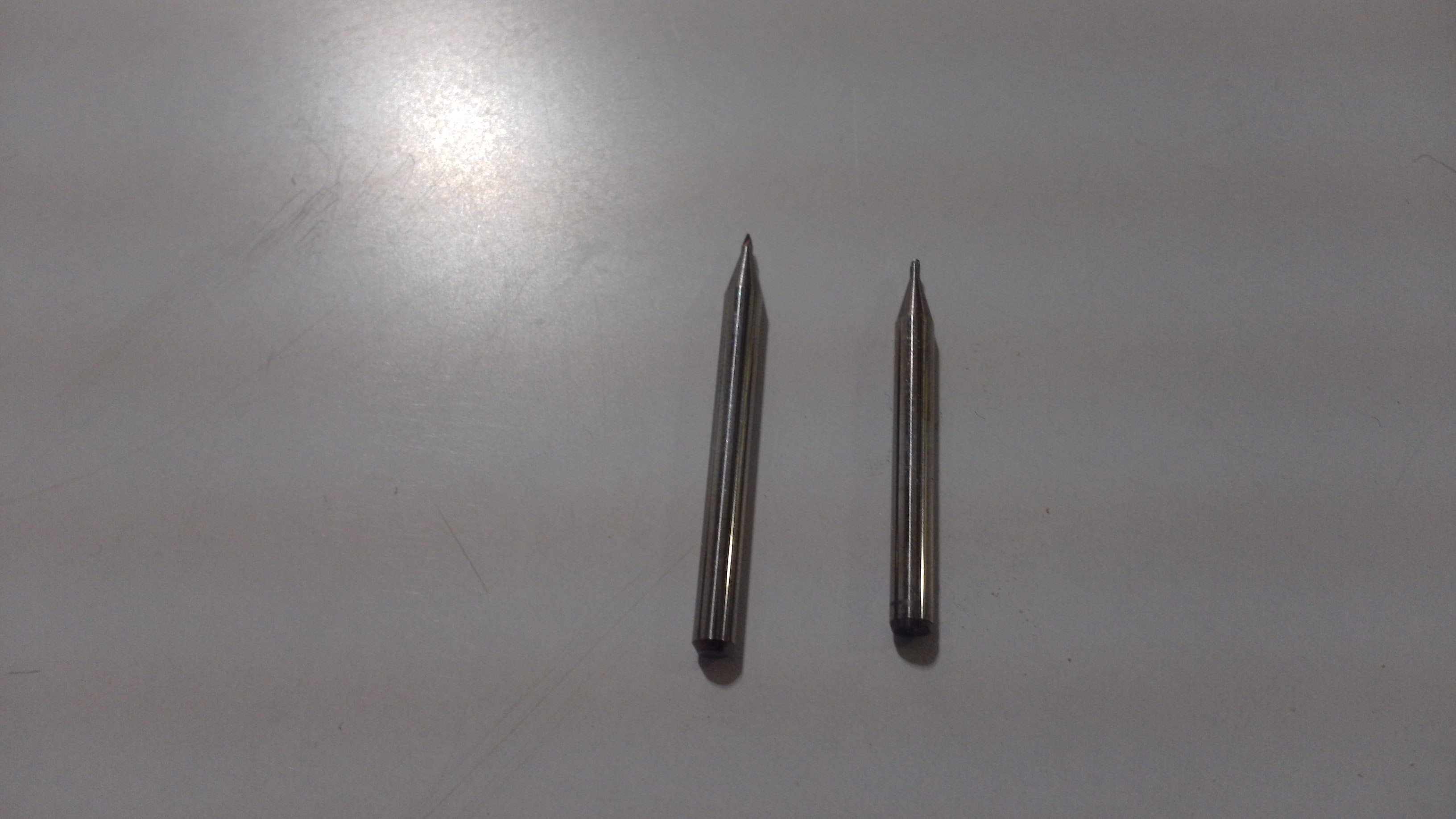
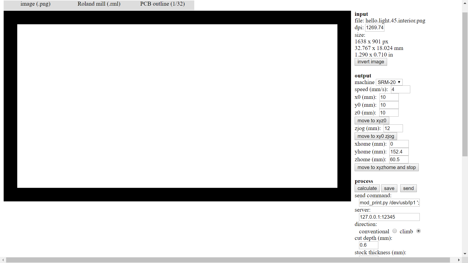
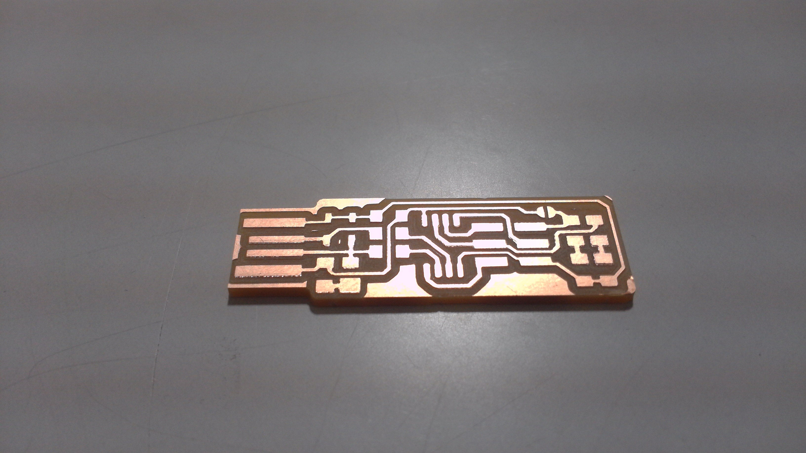
Once the the traces where cut, I then had to cut the board out of the main sheet of material. In order to do this I switched to a larger 1/32 router and loaded a new file for the outline of the board. Once again I calculated the code and fed it to the machine.
This time I found it was much, much easier to get the cut to work properly, the extra thickness of the bit meant that it was far more durable and thus much easier to to use without breaking it.
Once the cut was done I peeled the board off and checked it for imperfections, thankfully it came out looking rather well.
The soldering:
Here is the bit where I struggled a bit more: Once the board was cut, it was time to solder all the components on to it. In order to make the progammer detailed in the tutorial, we had to use the following components
-
one ATtiny45
-
Resistors: one 1kΩ resistors, two 499Ω resistors, two 49Ω resistors
-
LEDs: 2 LEDs of diferent colours, in my case I used one red and one green, however any two diferent colours can be used.
-
Two 3.3v zener diodes
-
One 100nF capacitor
-
One 3x2 pin header
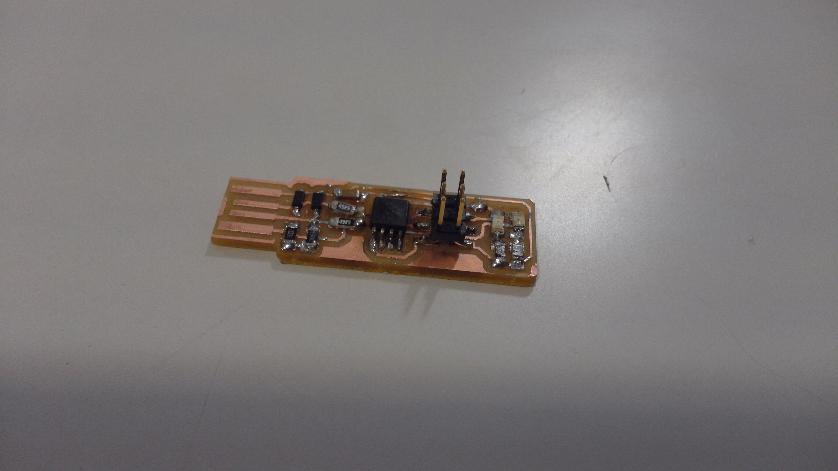
Having all the components on hand I began to solder them into the board. I had nevered soldered before, so it took me a while to get all the pieces together. I have read this before, but it cannot be repeated enough: the key to soldering is lots of light and lots of patience!
I followed the diagram in the Fab Lab tutorial page in order to guide me as to where all the components should be located in the board. I had to take extra precautions because some of the components have an orientation, and will not work if placed on the board the wrong way around.
Finally, after a long while and much cursing, I soldered the last component into the board. As it stands, the soldering is quite sloppy and some of the parts where not perfectly straight, however it looked good enough for my first attempt.
The coding:
Having my board cut and soldered it was time to programme it so it might be used as a programmer itself. In order to do this I followed Brians tutorial from the Fab Academy page. I followed all the steps effortlessly up untill the final step of Make Flash. And it was here where I got stuck.
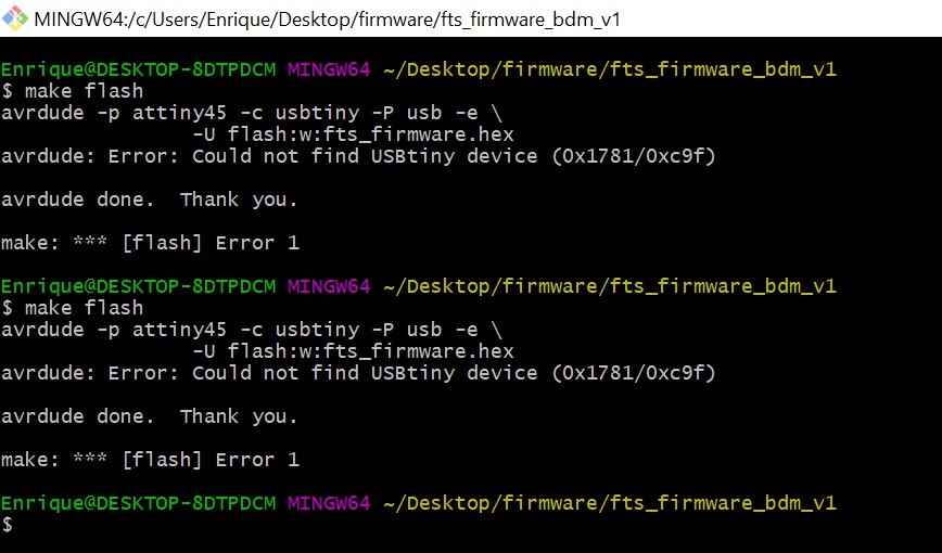
For some reason unbeknownst to me, this step failed time and time again. I attempted various posible solutions: I re installed the various drivers, tried on a diferent computers and used two diferent programers with two diferent sets of wires. Eventually, after about an hour of trial and error, the board suddenlly worked for no particular reason upon being unplugged and re pluggled for the millionth time. I am still unsure of what caused the failure to begin with, or what it was I did that solved it.
The burn:
All was going well witht the bard: I had managed to test that it indeed worked and my computer was reading it fine. It had been plugged for an hour or so when suddenly a faint trail of smoke started emmanating for it. I took it out of the pc but by then the damage was done, the ISP had burned.
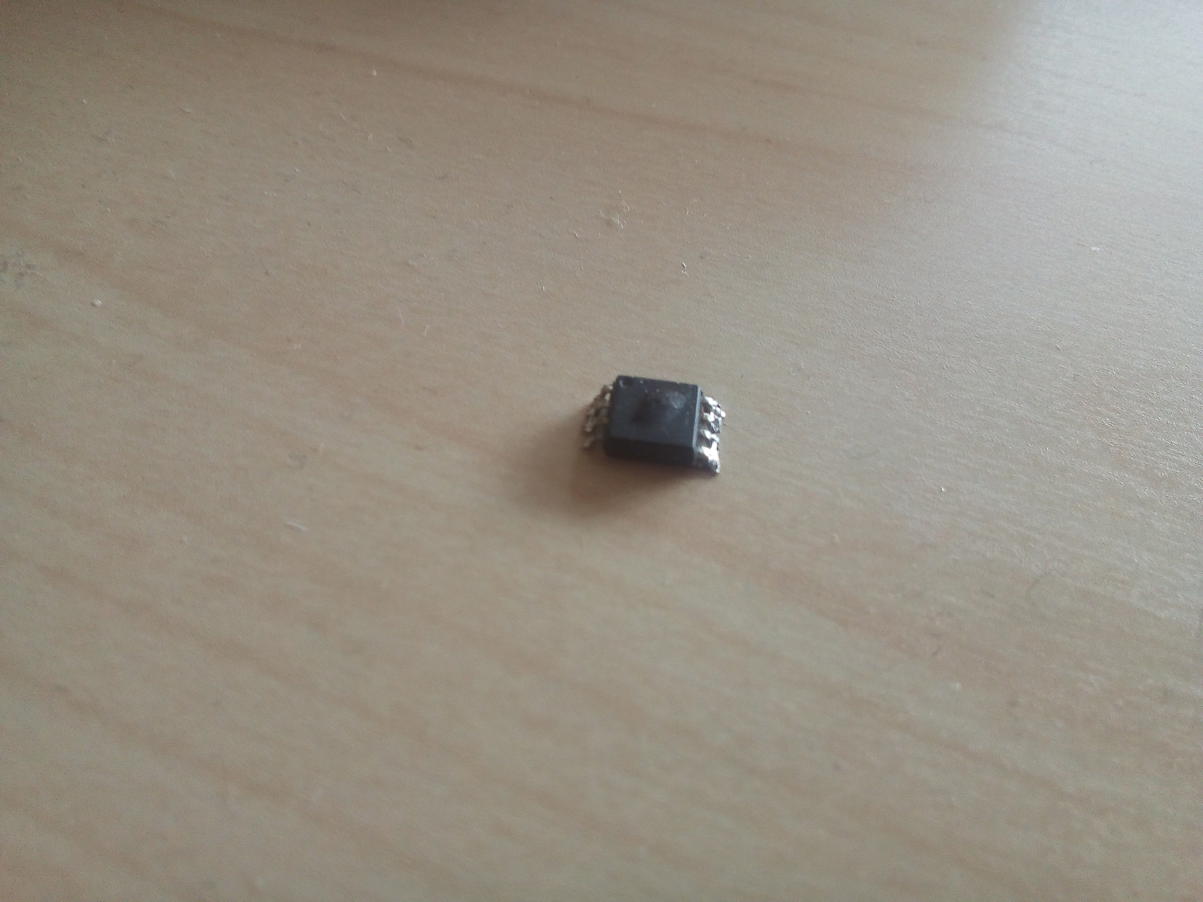
I am not sure what caused the ISP to burn in the first place exactly, I had been using it for several hours at this point and all seemed to be going well. I suspect that my shoddy soldering made it overheat slowly untill the point where it fried.
Thus, I had to remove the ISP from the board, solder a new one, and start again.