17. Machine design
Designing the machine
Since the SCARA machine has a central rotating axis, this means it has no natural front and back. As such a static camera could give us issues, so we designed a Dolly system to move the camera. This would allow us to calibrate the machine more easily, as well as add another point of movement which could be used to make more imaginative designs.
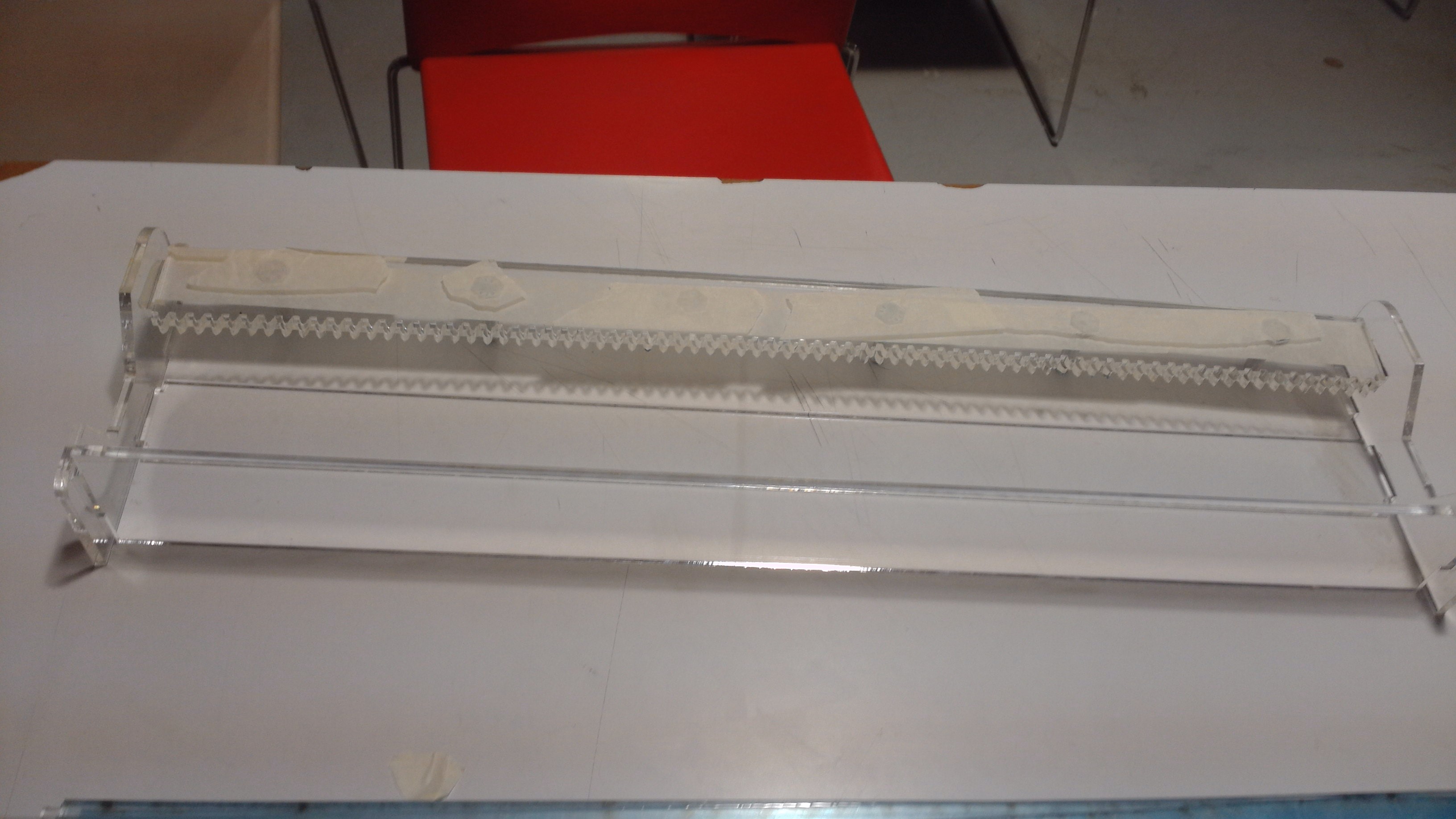
First we made the track. The track consists of various laser cut acrylic pieces, held together by snapfitting into one another. At first designed just the main rail, these worked well during testing, however once we added the stepper motor it proved to be too unstable due to the extra weight. Because of that, we decided to add a second piece in order to balance it out. This added a bit of complexity as we had to re design the rail, however the added stability proved invaluable.
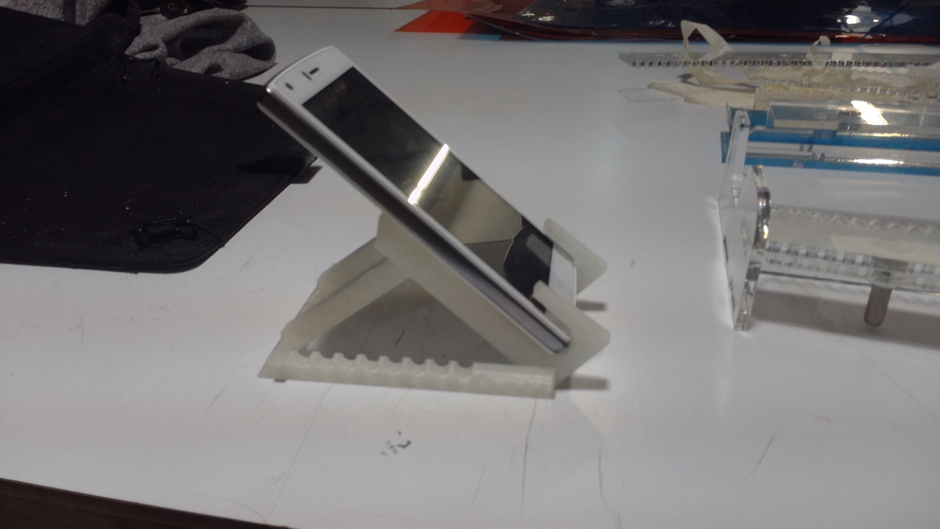
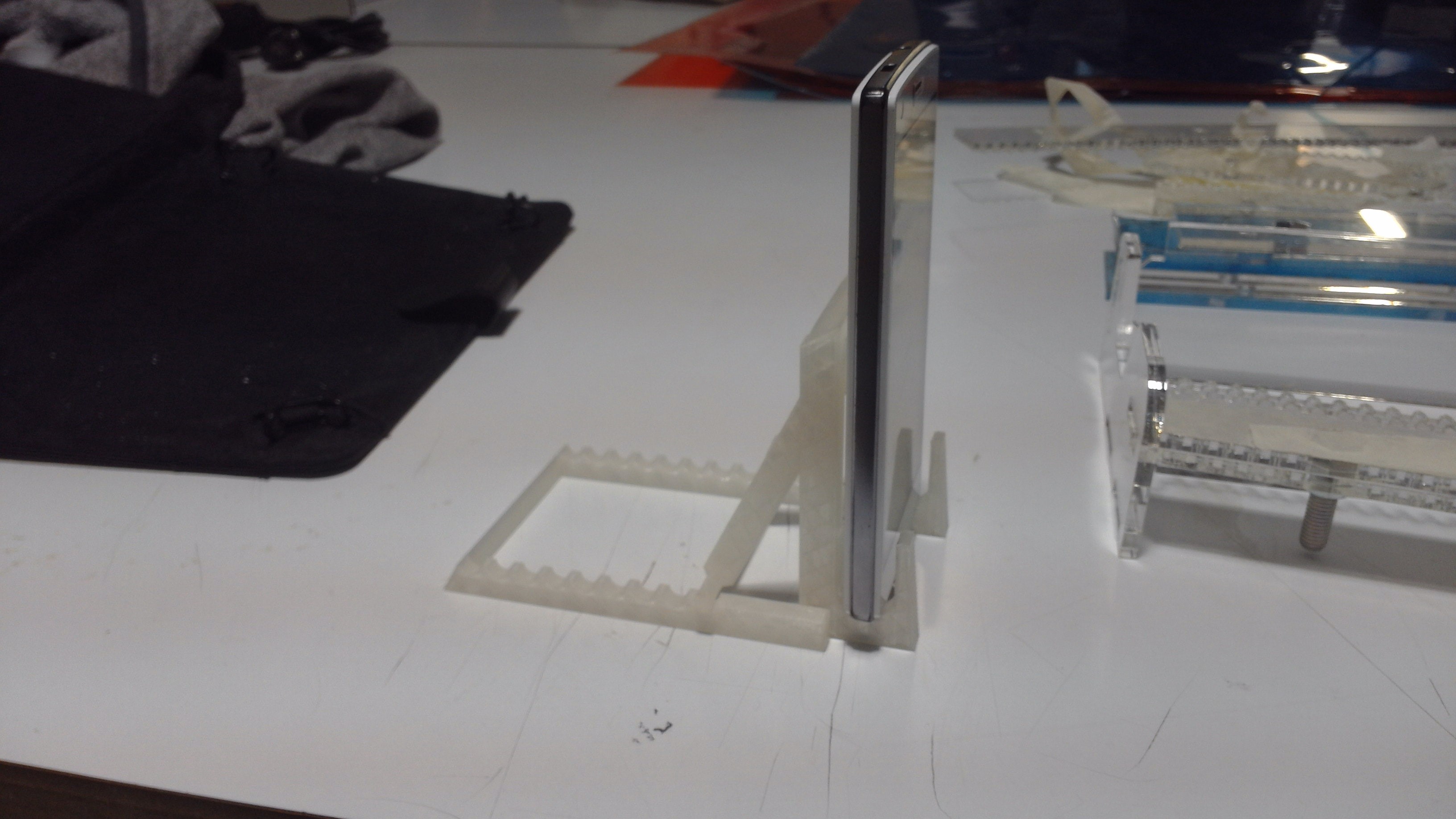
After the track and the carriage where assembled, we creted the stand that would hold the phone used to take the picture. Originally we wanted to add yet another motor which would control the angle of the camera, however that proved to be far too complicated for the ammount of time we had, so eventually we just settled for a manual stand. We added extra grooves on the carriage which would then allow for the stand to fit snugly on top, without falling ver when moved.
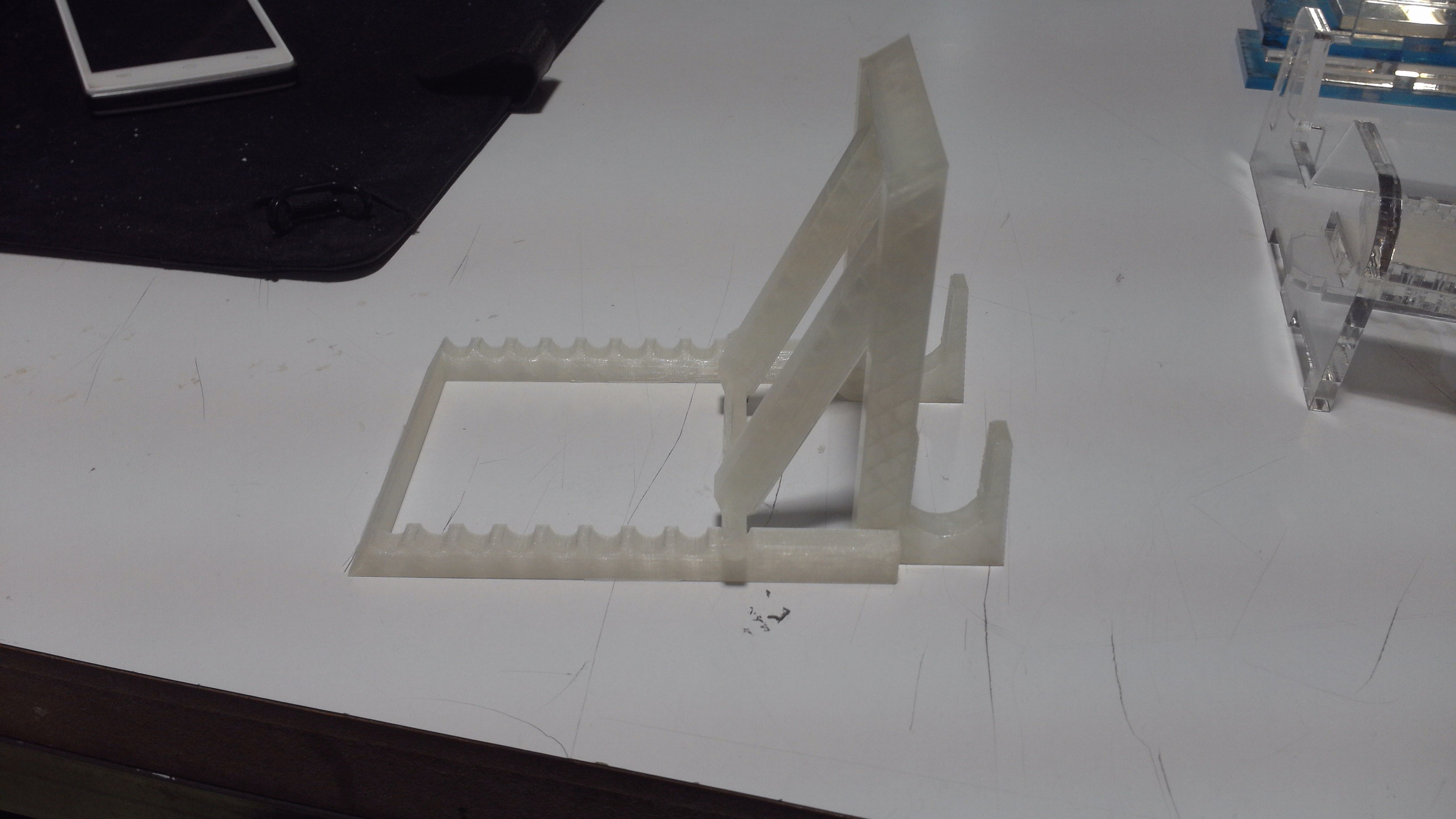
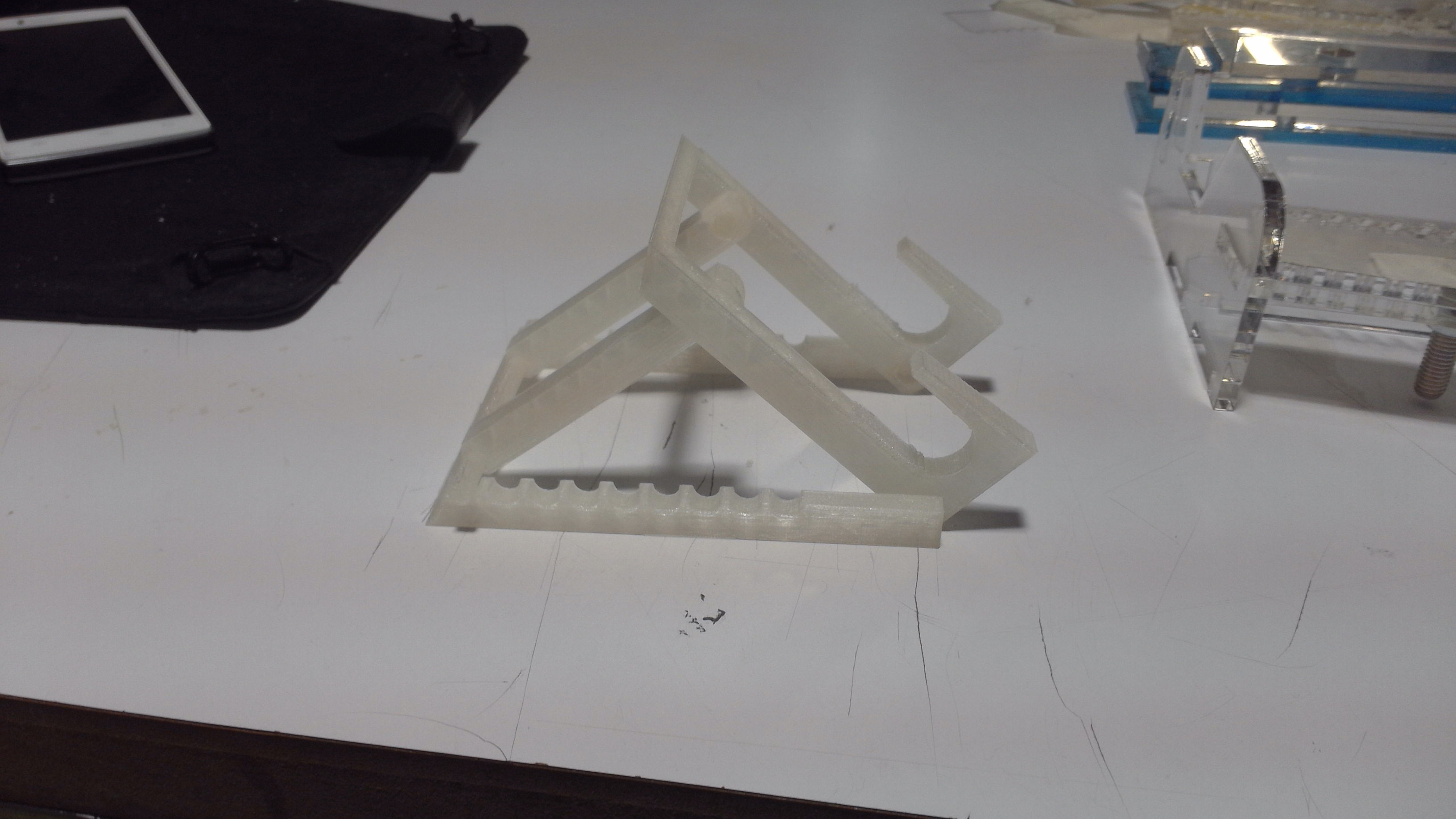
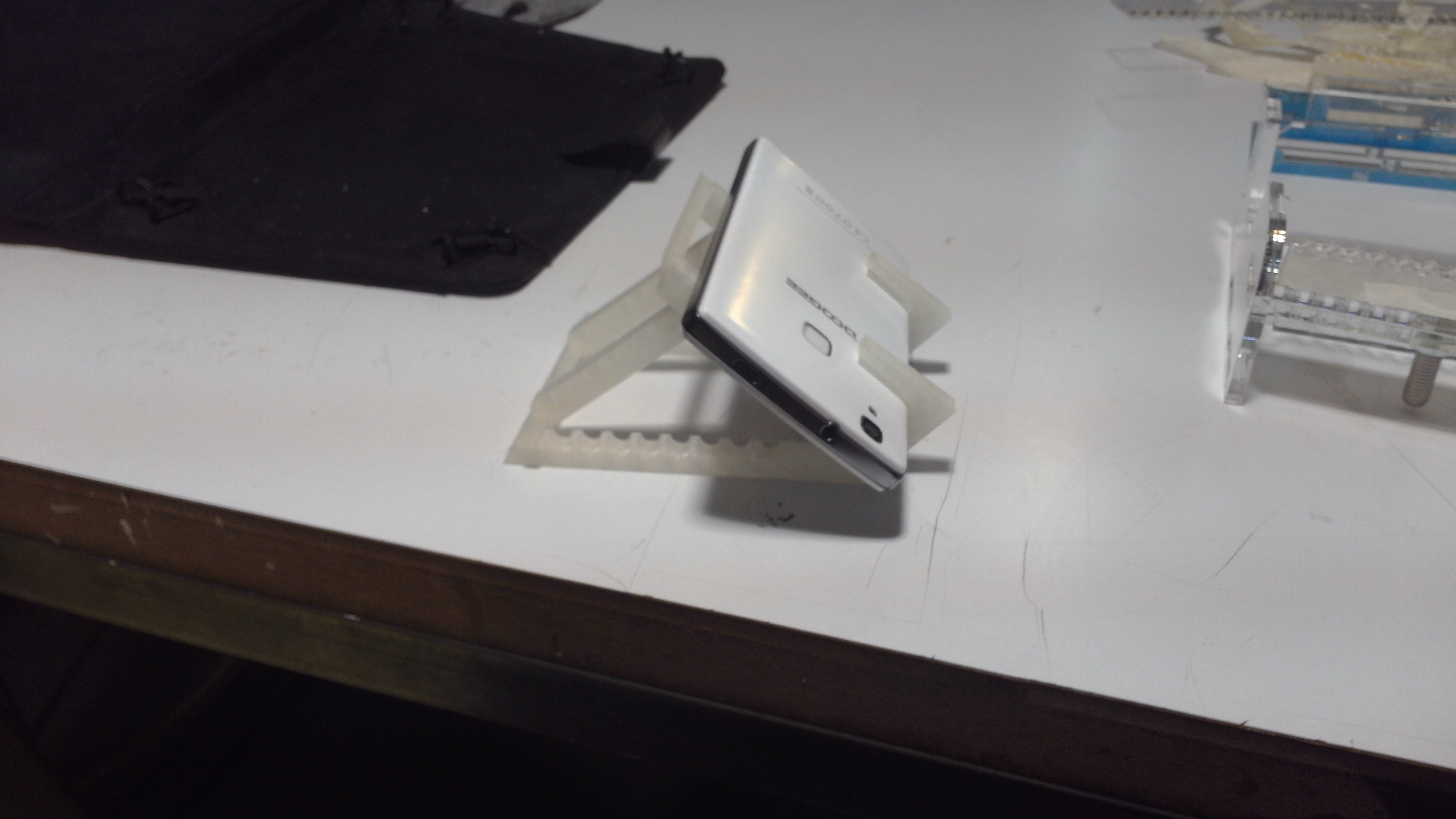
Additional consideration was put insuring that the stand could mount a variety of devices, as phones come in a variety of shapes, sizes and thickness. It was also designed so the device could be mounted in diferent positions so as to be able to get the desired angle. The stand can also be mounted both forwards or backwards for extra customization. In theory it should also be able to mount tablets or web cameras, however we have not tested this capability.
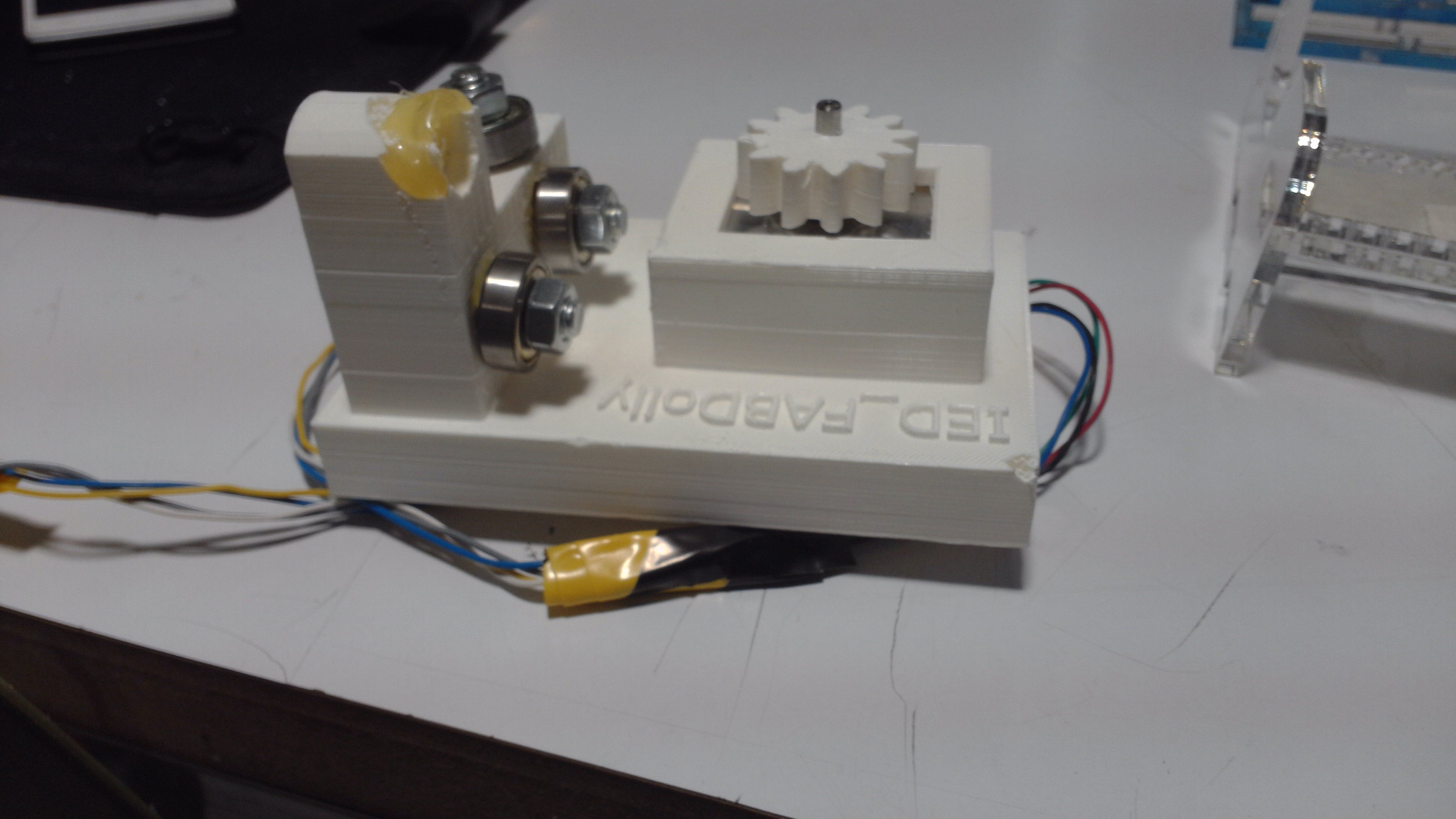
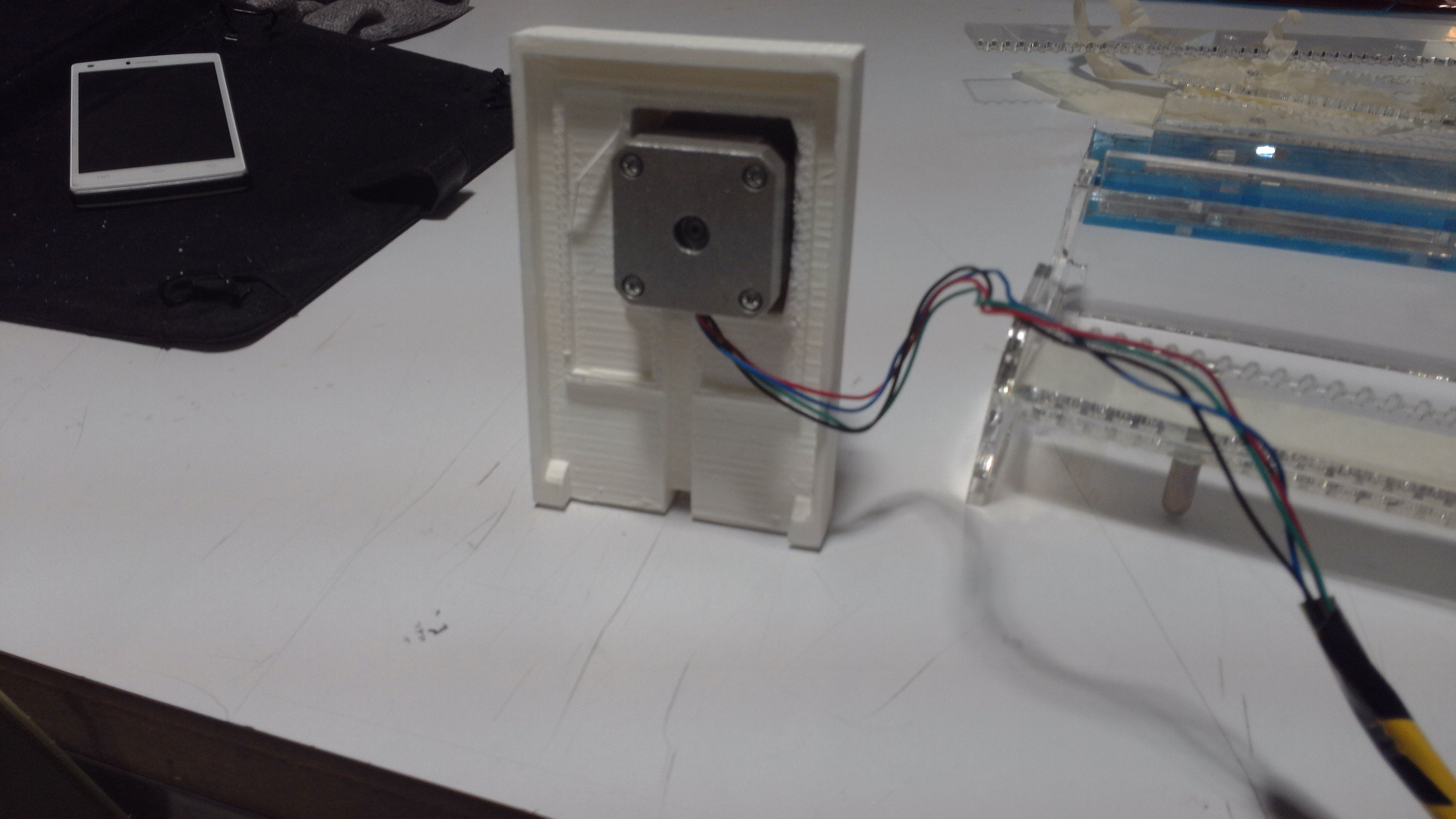
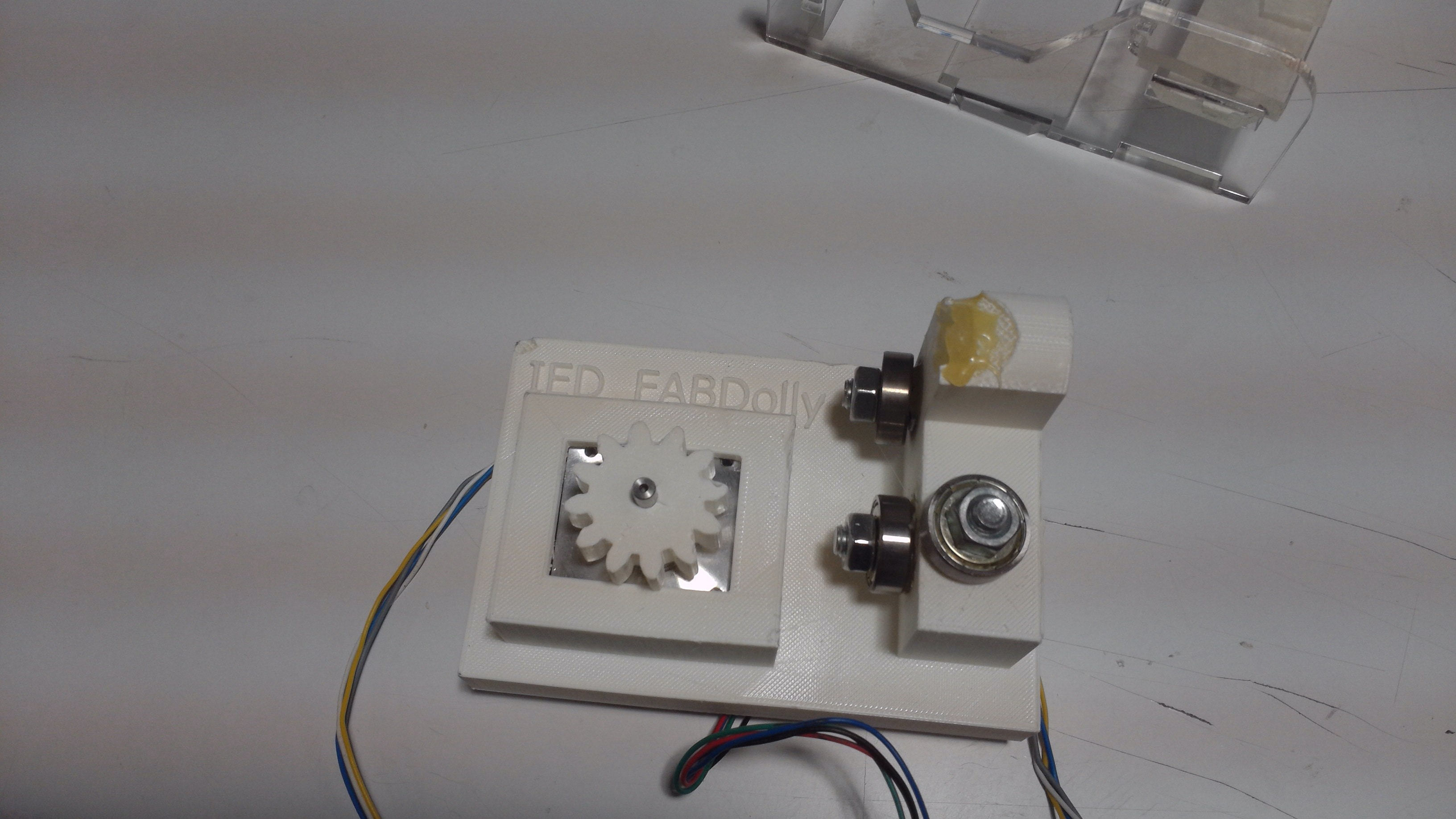
The carriage body was3d printed as the shape was far too complex to create in any other way. We added a middle pocket where we could fir the stepped motor that would drive the movement along the track. For this we 3d printed a custom cog to work with track we laser cut. Then we added extra dumb wheels. Originally we wanted to 3d print them too, however the performance was less than ideal, so eventually we settled for using bearings. In order to secure these, we fitted a screwhead into the carriage. The screwheas snap fit, but we added a slight ammount of adhesive for good measure. The we capped the bearing with a nut. All in all, we added four guide wheels. Once all the wheels are in place it is impossible to remove the carriage from the rail, so we made sure to leave ample room to be able to unattach the nuts so we remove the wheels in case we needed to make changes to the carriage. This proved a great idea as we had to re print the carriage multiple times to make changes, as well as to fix the damage it sustained when we accidently dropped it once.