"" -
Input Devices
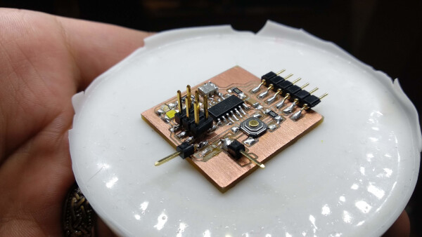
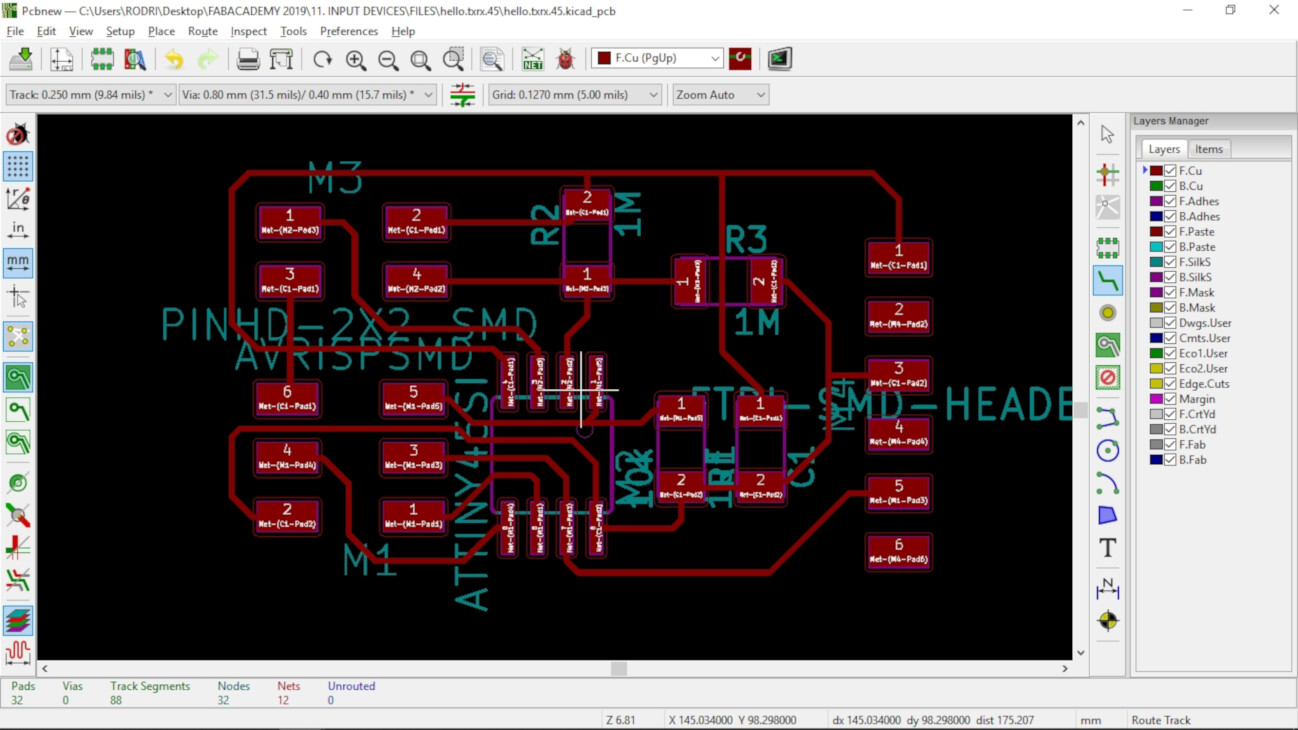
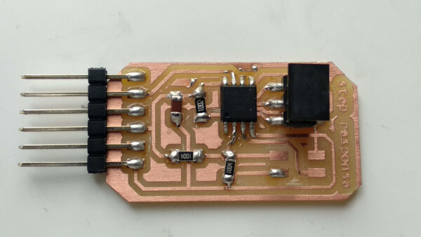
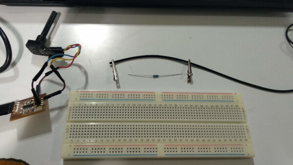
For this assignment I used my BoredBoard, making some repairs on the pins, to have an Analog Pin, a GND and a VCC pins.
Setting up
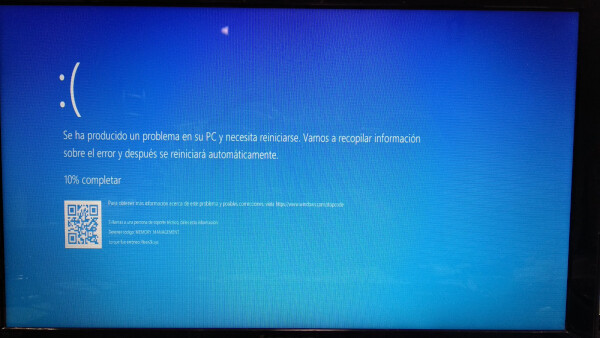
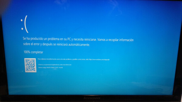
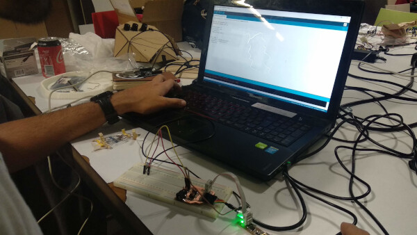
I tried using a previous code of some Serial Test to print the data but had two blue screens of death when trying with the serial Monitor and switching between the usb ports. Maybe is because of the usb2.0 and 3.0 of my laptop. I will try switching the ports again to see if that happens again (I was trying with the teo usb ports on the left side of the laptop when the blue screens happened). I used the multimeter to see if everything on the BoredBoard was okay after doing some fixes (soldering some pins for the potentiometer). I noticed that the COM ports apperead, even though I had nothing connected on the laptop, I noticed after change the usb ports and still seeing the COM26.
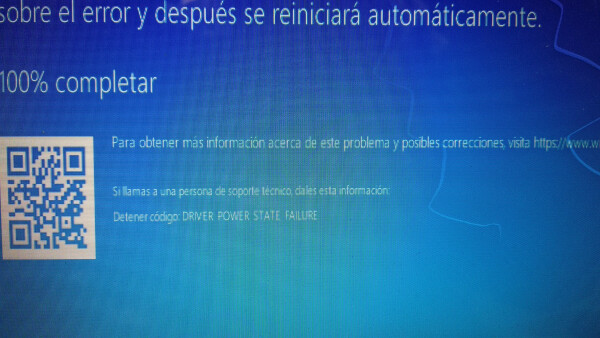
I did a lot experiments disconnecting and reconnecting the usb ports, into different configurations an neither worked. I entered the device manager and saw that the COM26 appeared always on. When I restarted the laptop without the ports connected, the COM26 will not appear. Also what seems strange is that I can upload code normally, I just can't open the serial monitor, and if I try and get the "port busy message" I run the risk to have a blue screen. Another blue screen that appeared when I tried to restar the laptop was the Power Drivers error...
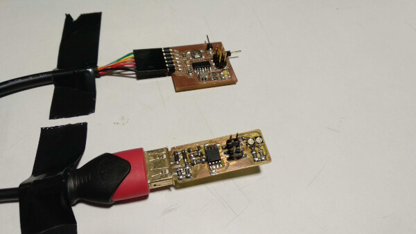
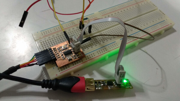
I finally managed to open the serial monitor: Turn off the computer (not restart) with the two usb ports conneected on the left side of the laptop (FTDI of BoredBoard closer to keyboard, and the other was the USB from the FabISP). Run the hello.ftdi.44.echo on the GIT BASH terminal as my documentation says in the programming in C section. Enable the COM26 on the device manager. Open terminal. At first the echo didn't worked fine, but after a few tries, reopen it, changing the baudrate and returnig it to 9600 at the end it worked.
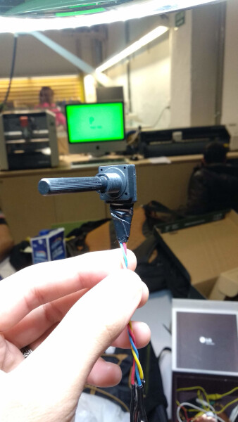
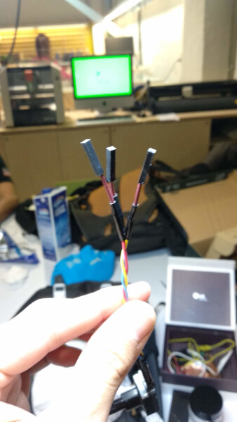
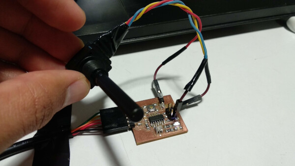
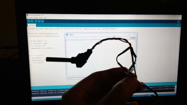
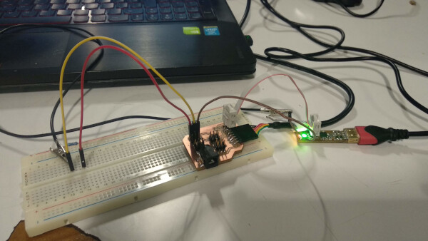
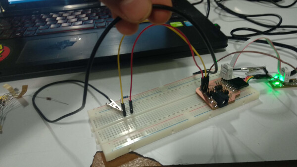
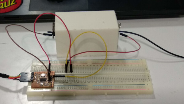
I wrote a simple Arduino code to print some potentiometer data. After I uploaded the code, I disconnected the ISP connector of the Bored Board to use the GN pin, and connected the signal and VCC to the potentiometer. I ran the serial monitor and it worked, but after a few moments it started to show some ? symbols. I added a delay(100), uploaded the code and again connected the potentiometer. This time the data was okay. (show video).
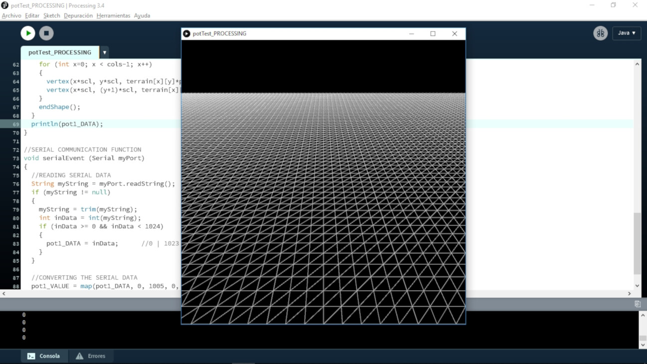
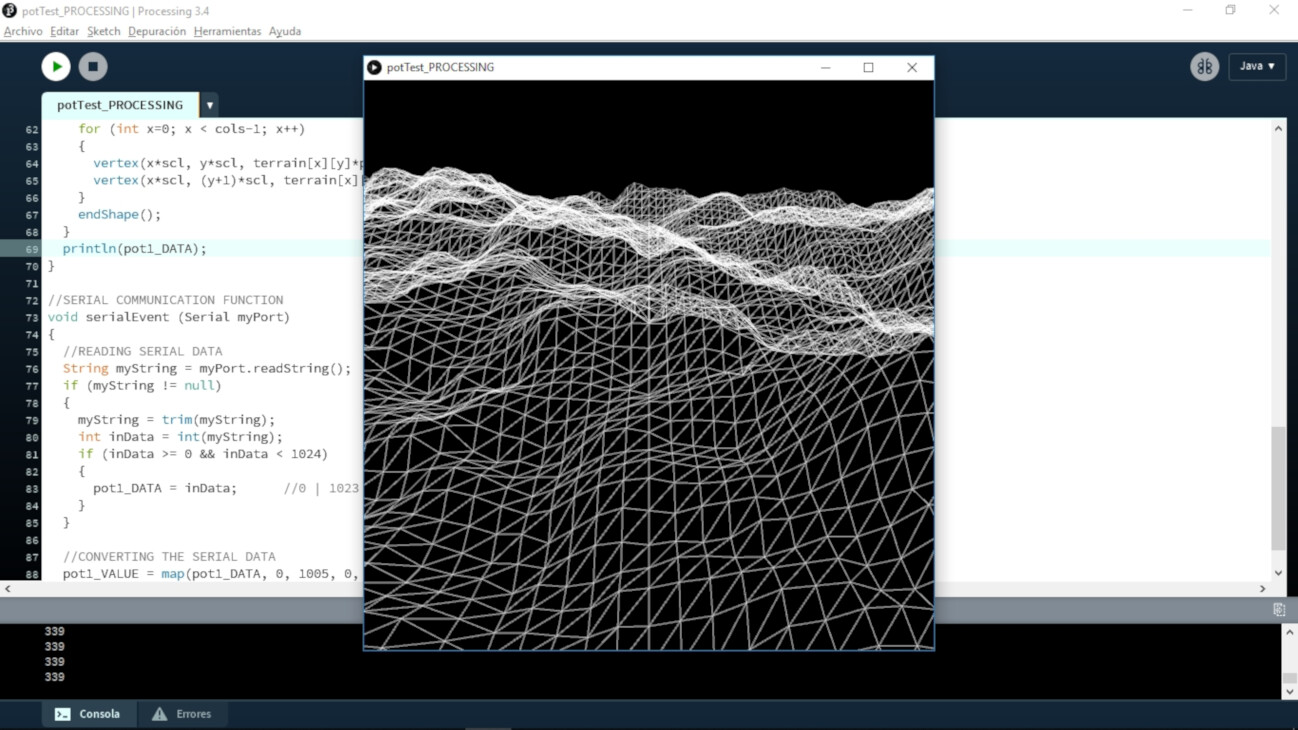
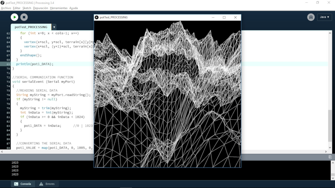
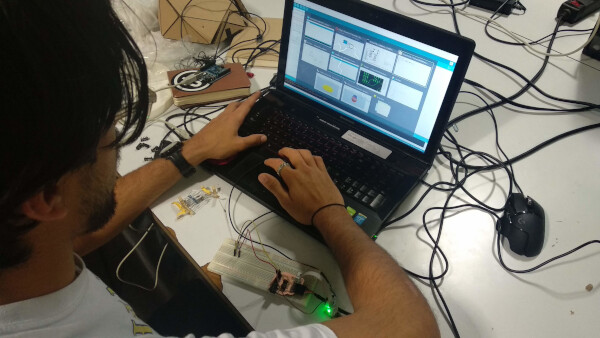
As I have used Arduino and Processing before, I wanted to test the output to some interesting visuals, so I modified a version fo the code by Daniel Shiffman, and used the potentiometer as the input for the height of the mountains. It worked really great! It didn't have any giberish. I'm absolutely satisfied with this result!
Step response sensor
In this week lecture I was absolutely amazed by the step response sensors. I knew the concept of step response as I took a class on control theory, but I didn't fully understand the concept applied here, because as Neil mentioned you can do many kind of sensors with this application. I was particulary fascinated with the touchpad, because I can totally use some input like this in my final project.
Integration with my final project
Previously I have worked with Arduino and Processing, integrating my console for visuals P_A+L! (Processing_Arduino+Lots of sensors!)
So the idea is to use a lot of sensors for the final project, so I designed one board that has many inputs
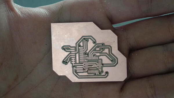
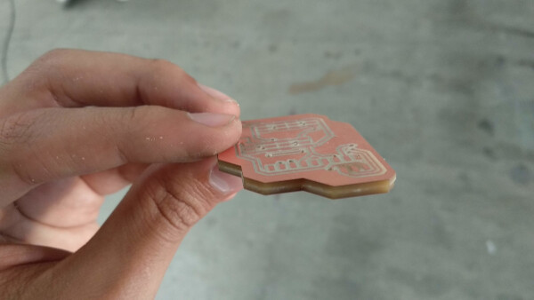
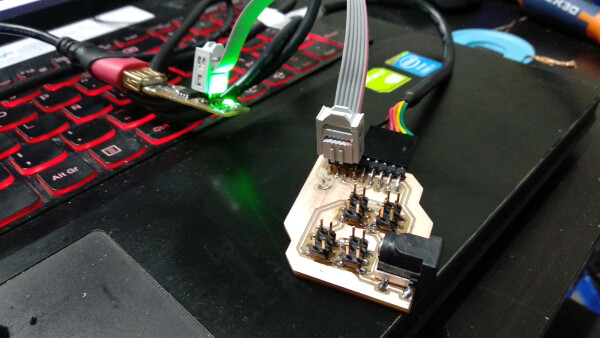
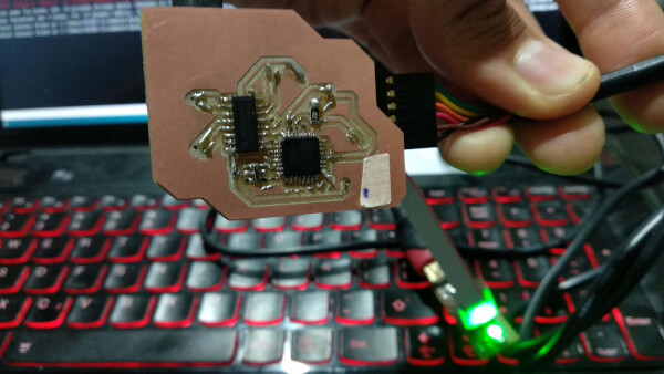
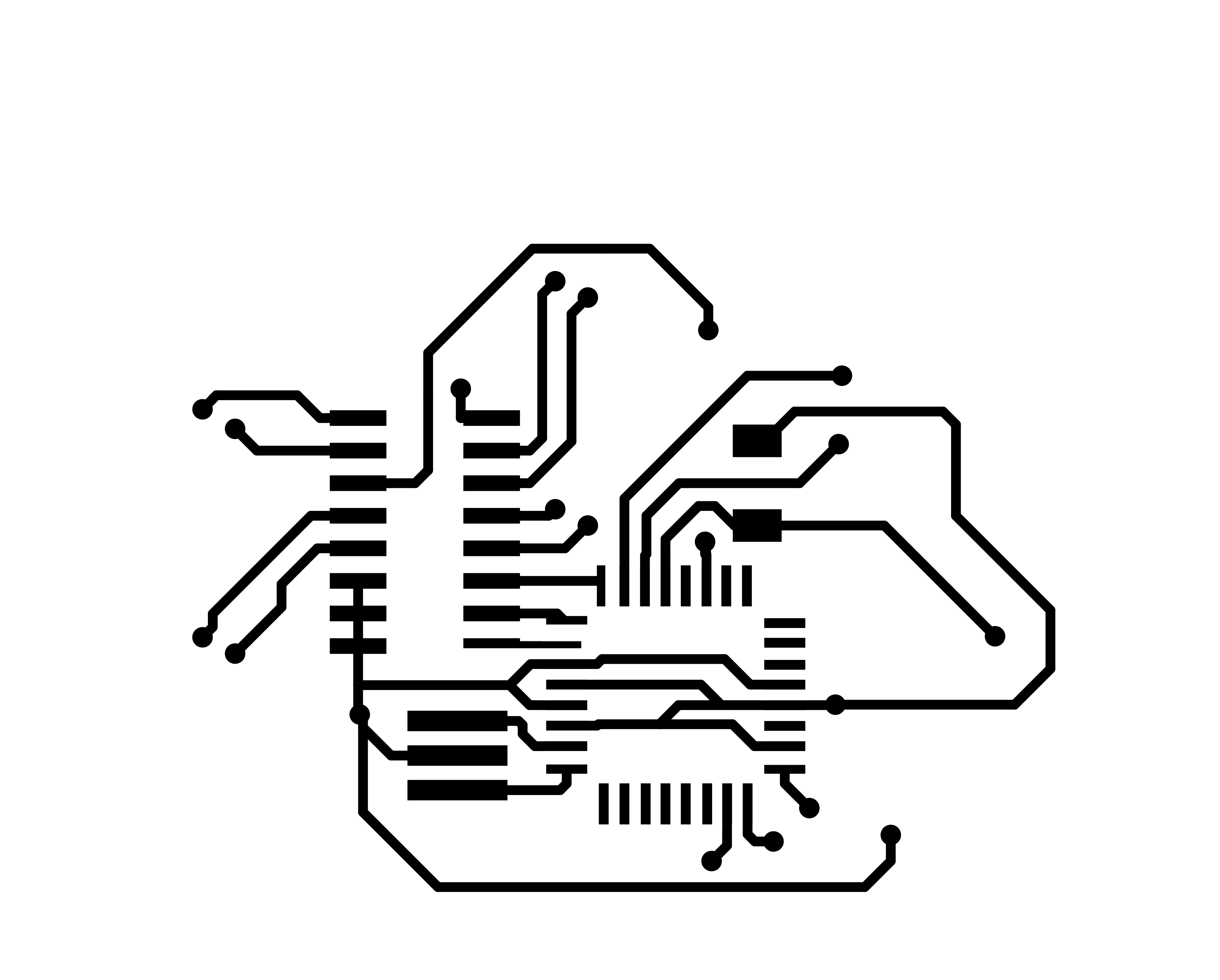
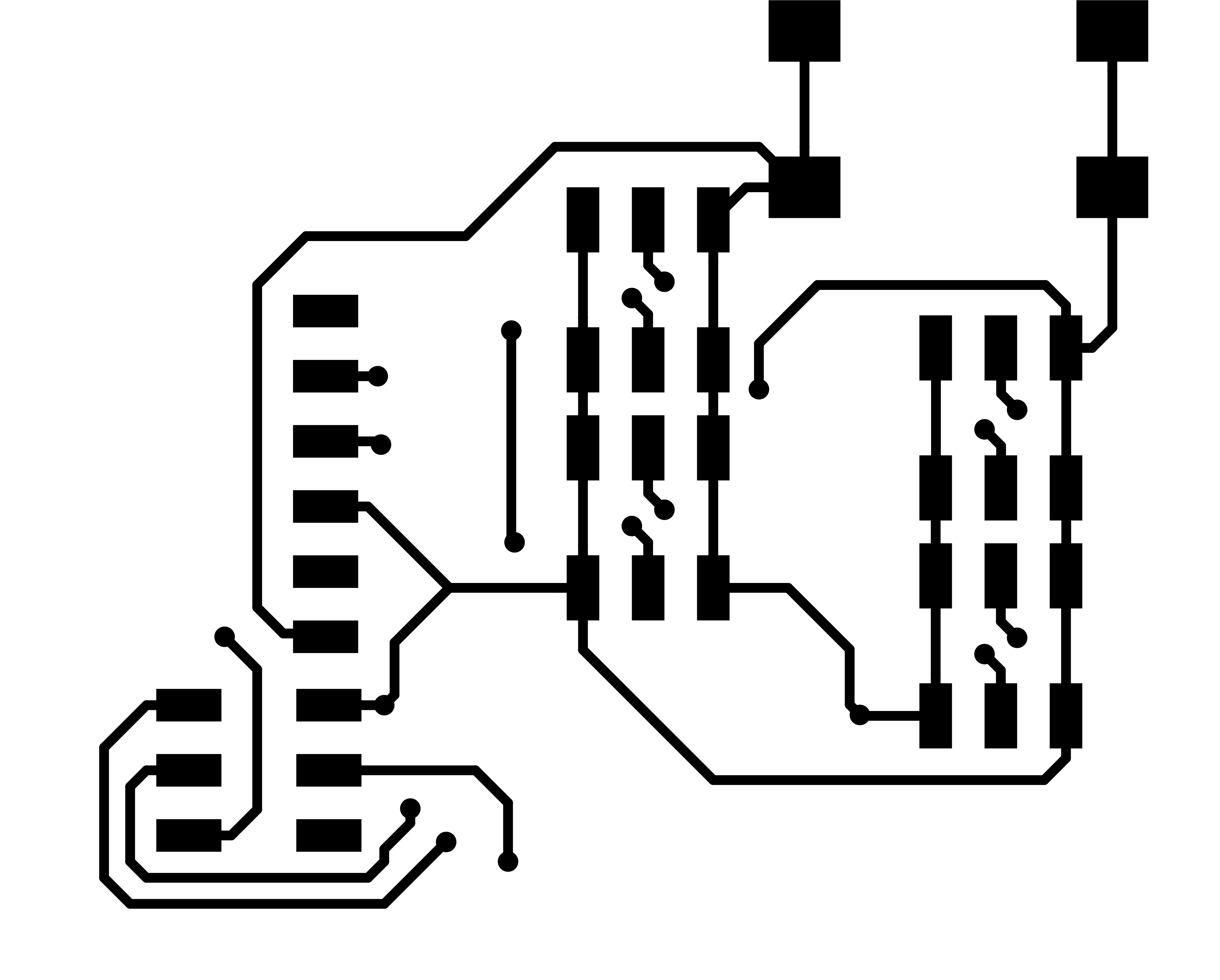
I begun designing in KiCAD the electronics for the main board of the console, using one multiplexer. To reduce the size of the board and to experiment on grouping components as the header pins where the sensors will attach, I decided on doing a double-side board. I learned how to design double-side circuits on KiCAD, and fabricated this board. On this board I used an ATMEGA328P as the microcontroller.
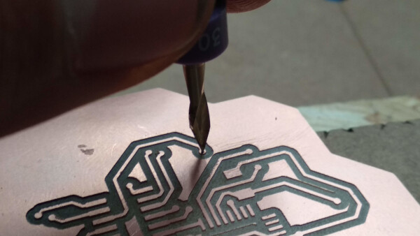
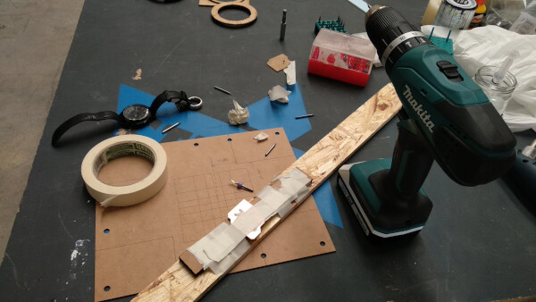
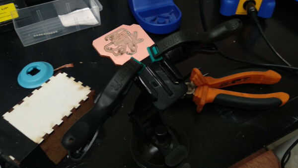
To connect both sides of the board between each other, I had to make drill holes on the points I decided on the design. To do this I first used a V shape drill bit to make a little hole, and then used a 1/32 drill bit to make the hole.
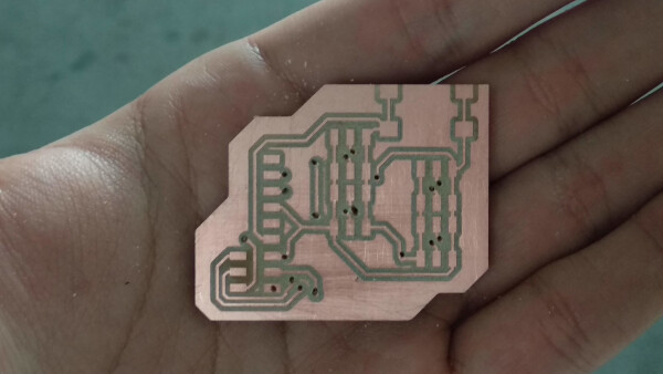
I then solder pins on the holes to connect the paths on both sides of the board, and cut the remaining parts of the pins. I then soldered all the components on both faces.
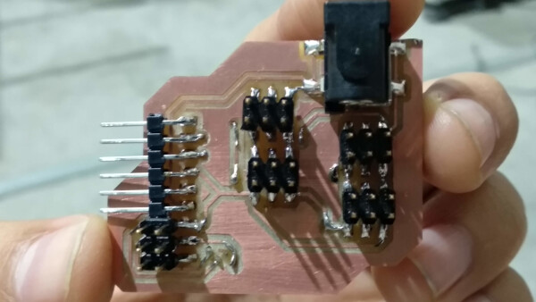
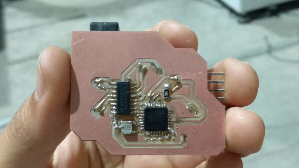
I then burned the bootloader using my fabISP. I connected a button as a test sensor to see if it worked and it did. I test this button on every header pin of the multiplexer, and they all worked.
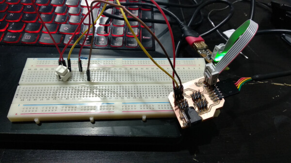
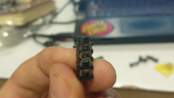
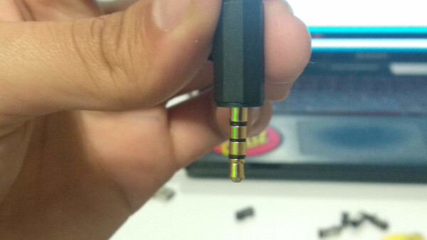
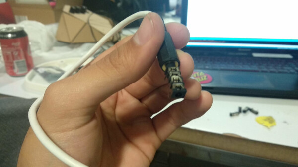
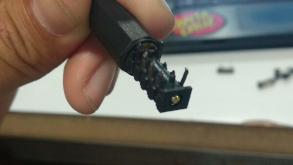
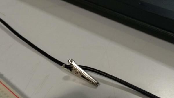
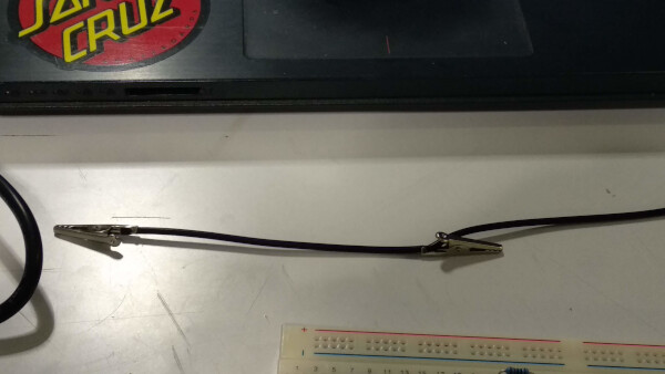
To connect the external sensors to the console, I used a 3.5mm plug. I connected the patch cable to my board through the 3.5mm female plug and the other side of the patch cable to a rubber cord I'll use on my soft sensor (down in the section of Soft Sensors I explained what is the electronics on this sensor). I tested, and as the button, it also worked.
Soft sensors
I wanted to fabricate some soft sensors to twist, bend and play while using the console and making visuals. To make this I used a conductive rubber cord stretch sensor. I used this tutorial to make the connections.
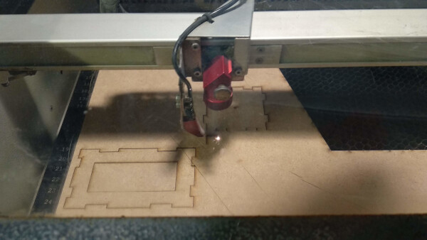
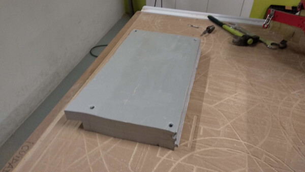
I wanted to make a test using silicone with the rubber sensor inside, so I fabricated a box to contain the silicone mix and hold the sensor inside.
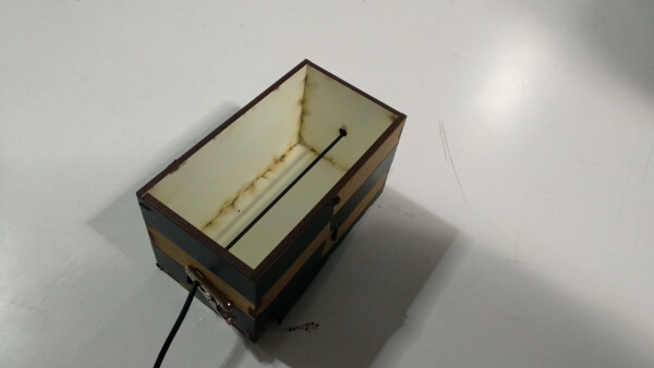
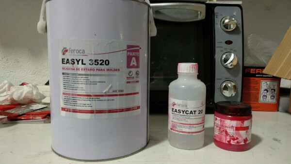
I used the same silicone as in my molding and casting assignment.
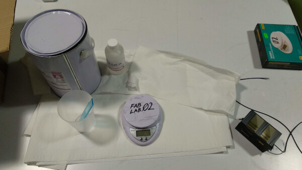
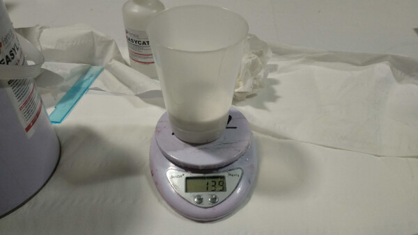
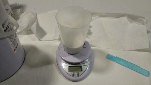
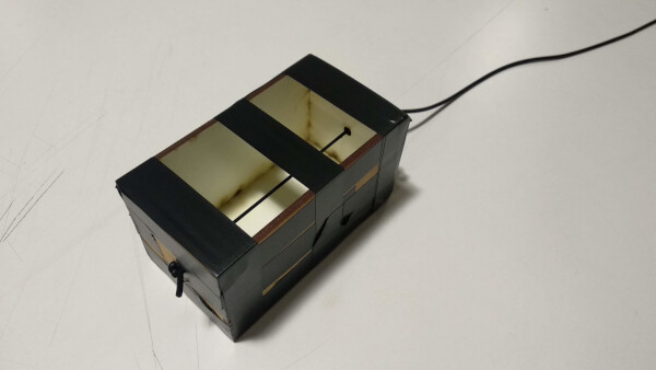
I poured the silicone mix inside the box with the rubber and let dry for 4-5 hours.
After that time, the silicone was dry. I actually really liked the texture and the density of the block, although the sharp corners where a little bit uncomfortable to twist, but the strenght and effort you have to make to twist and bend this block it's really aligned to what I want this to become.
I connected the outside parts of the rubber cord to my BoredBoard, from my input device week. I used the same interface application in Processing from that week to visualize the response of the sensor.
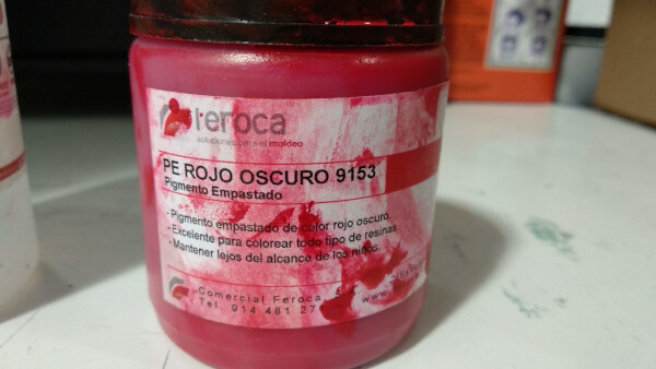
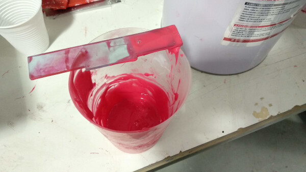
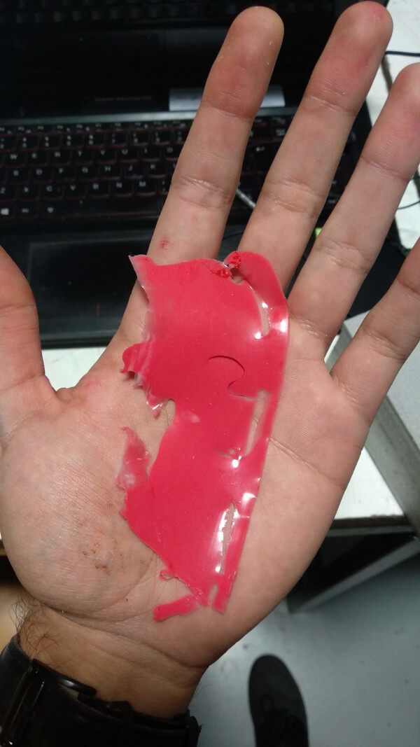
I wanted the silicone to have some color, so I did a test with a paste red pigment. This pigment is for coloring resin, so I wasn't sure it would work on the silicone. I made a little mix and poured a little bit of the paste, mix it until it was all colored and let it dry. The silicone colored succesfully, and it seemed that it didn't lose it's properties.
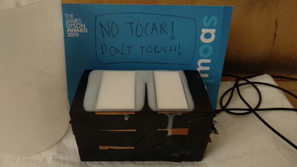
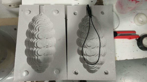
To make the final silicone sensor, I desgined and milled a low-resolution shape, because I think it would be nice for the feeling and grabbing. I milled it with the CNC machine on foam.
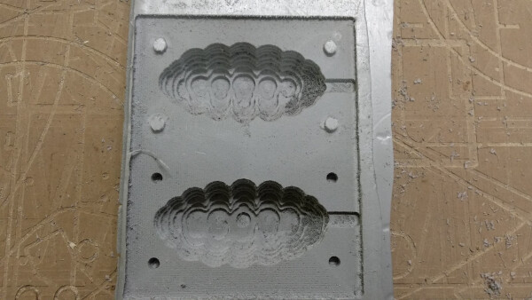
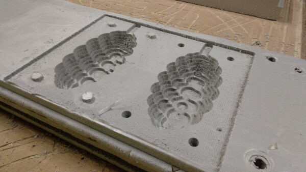
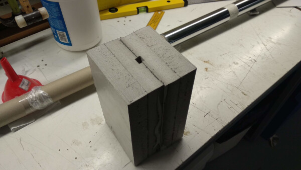
The foam block has hole for pouring the silicone mix, and to hold the connector of the sensor.
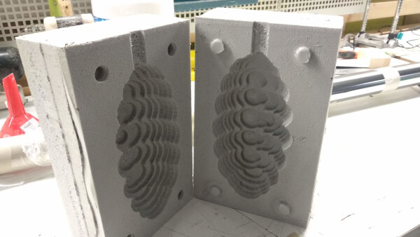
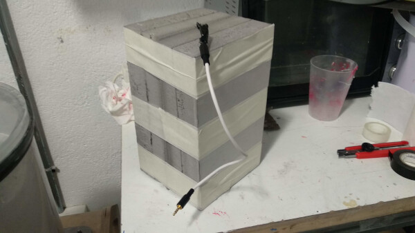
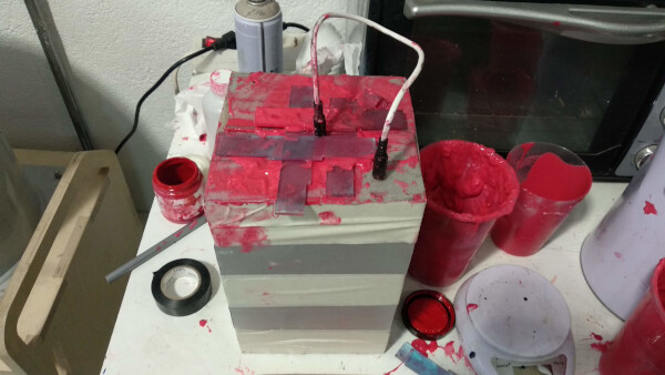
I closed the foam blocks using tape. The little grippers I made on the design were very helpful to close tight the blocks. I then made the mixture and poured it. The process was a big mess, so I had to make a bigger hole to poured the mix. I let the mixture dry for 5-6 hours.
Opening the blocks was a challenge as I forgot to put mold release on the foam. This was the final result of the sensor. I was very happy with the shape, the density and weight, as is a little heavy and you really have to make some force to bend it and twist it.

Files
- Potentiometer test code .ino (Arduino)
- Potentiometer test code .pde (Processing)
- Traces Board (Front Side) .png
- Profile Board (Front Side) .png
- Traces Board (Back Side) .png
- Profile Board (Back Side) .png
- Data Serial Test Code .ino (Arduino)
- Multiplexer Test Code .ino (Arduino)
- Soft Sensor Test Code .pde (Processing)
- Electronics Design Project (Complete KiCAD folder)