


I have taken this week's assignment as an oppurtunity to create something for my final project. Our task was to use an input device as a sensor to read specific data and display them on the serial monitor. And so I have used a DC motor's generating abilities.
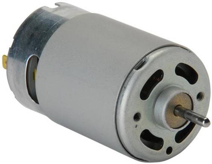
DC motors consist of coils surrounding a shaft, and when a current passes through the coils it will create a magnetic field that will cause the shaft to rotate. And the higher the voltage applied to the motor, the higher the rpm it will have.
What I intended to do is force the shaft to rotate causing a reversed magnetic field to generate a voltage difference between the motors pols. This voltage will be read as an input signal by the microcontroller and displayed in the serial monitor.
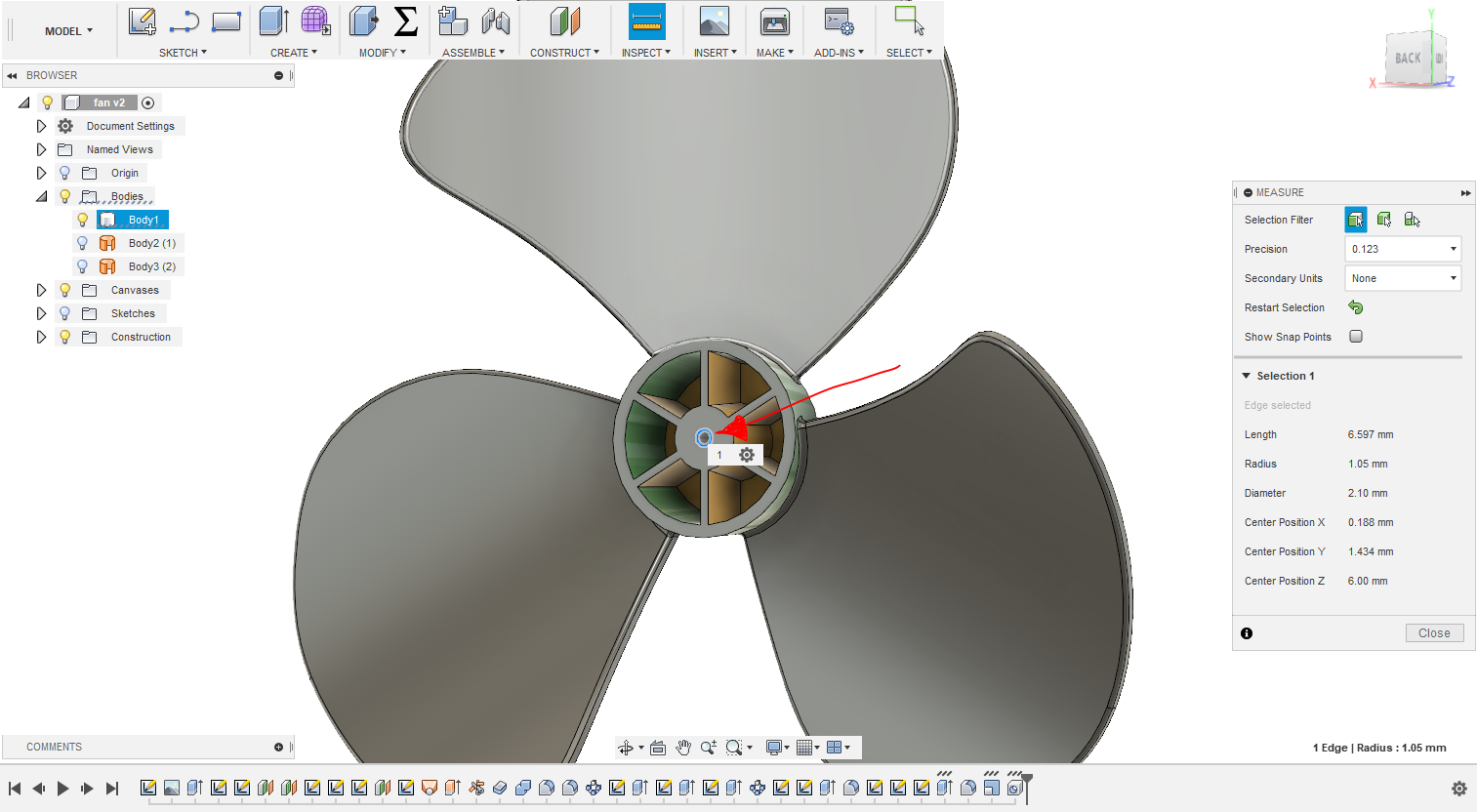
In order to create a mechanism to rotate the shaft, I downloaded and adjusted this design of a windmil fan. to be 3D printed, taking into concern the radius of the shaft slot to be alligned with the shaft of the DC motor I am using and leaving 0.1 mm clearence as 3D printer tolerance.
The fan was printed using PLA on Ultimaker 2+. The supports where then removed and the surface smoothed.
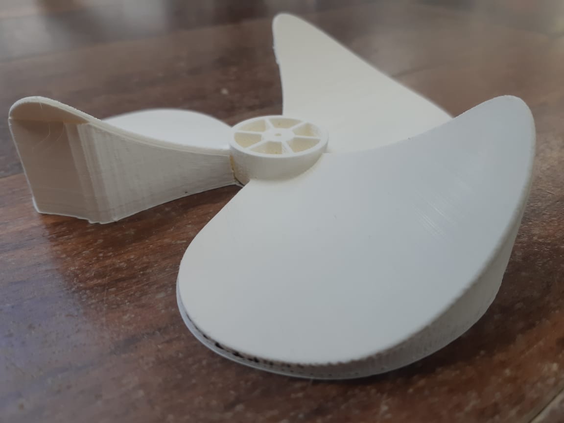
After finishing the fan and attaching it to the DC motor, I connected the motor to a multimeter then using an airgun, tested the output voltage.
After testing multiple DC motors for highest output voltage possible, I settled on a DC motor that gave 7V output.
Now this DC motor shall be connected to the board which works on Atmega 328p. Meaning the voltage applied to the board must not exceed 5V. So I had to create a voltage devider.
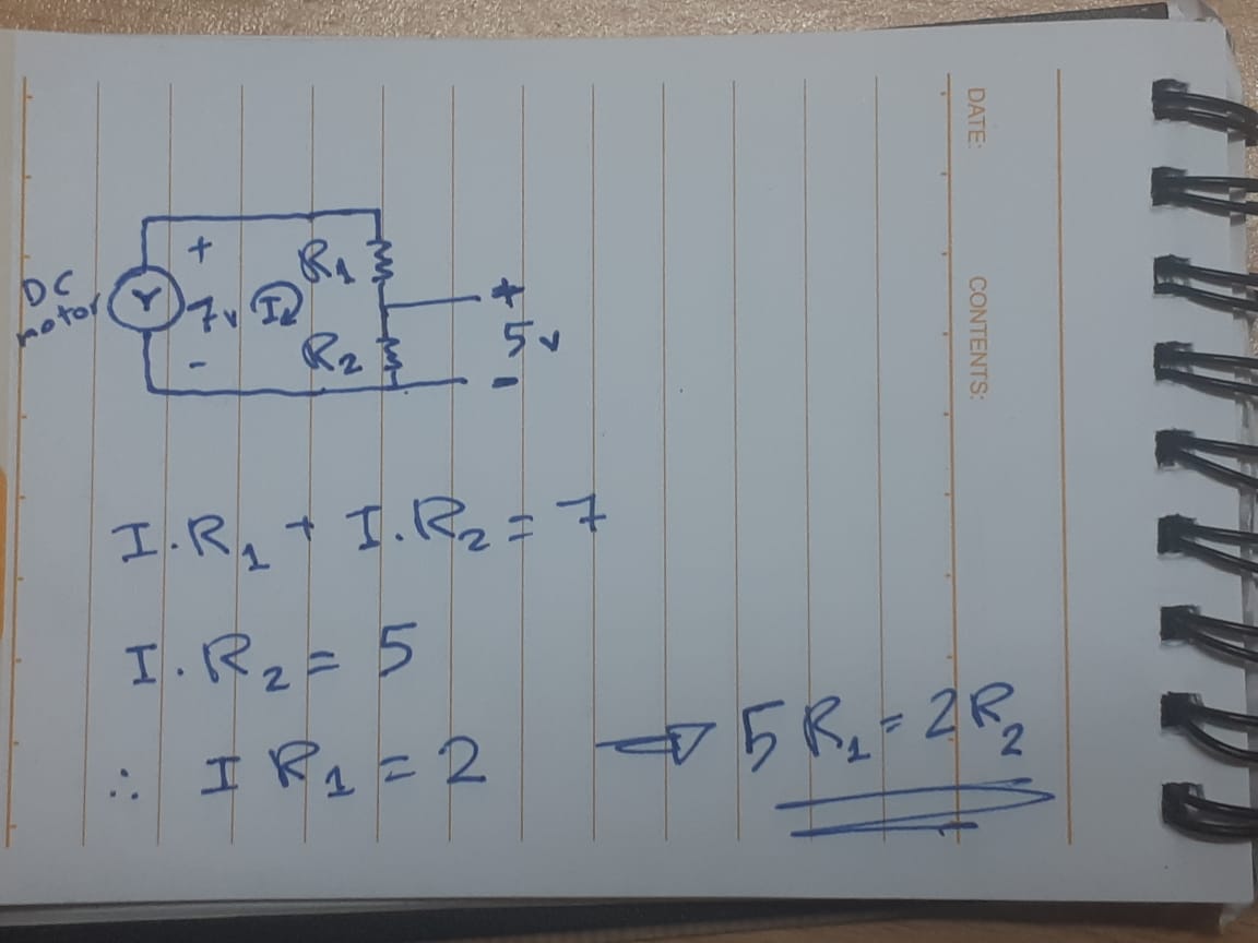
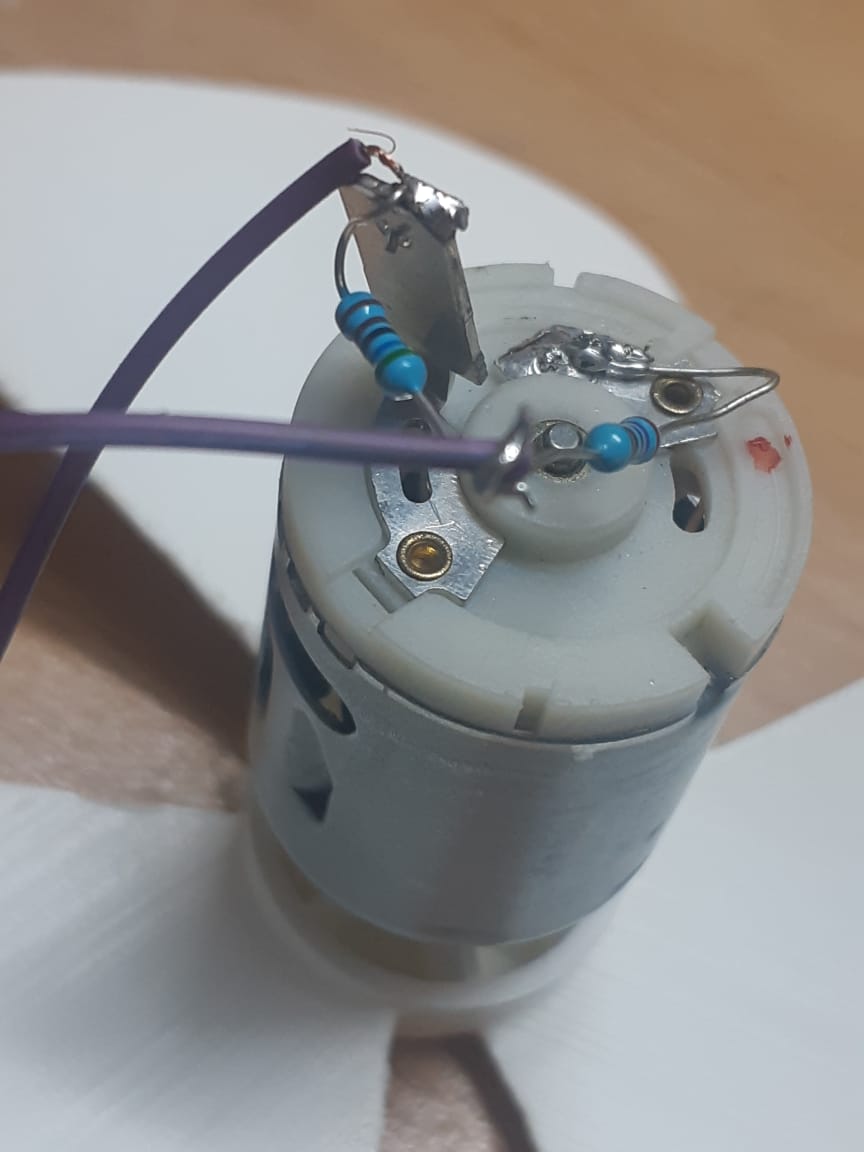
I found that the ratio between the two resistors must be roughly 2:5 (redusing the ratio toward 2:4 is a safety factor to ensure that the voltage would not exceed 5V at any rate). so I used 270 Ohm for R1 and 560 Ohm for R2. Then I soldered the resistors on the DC motor.
---
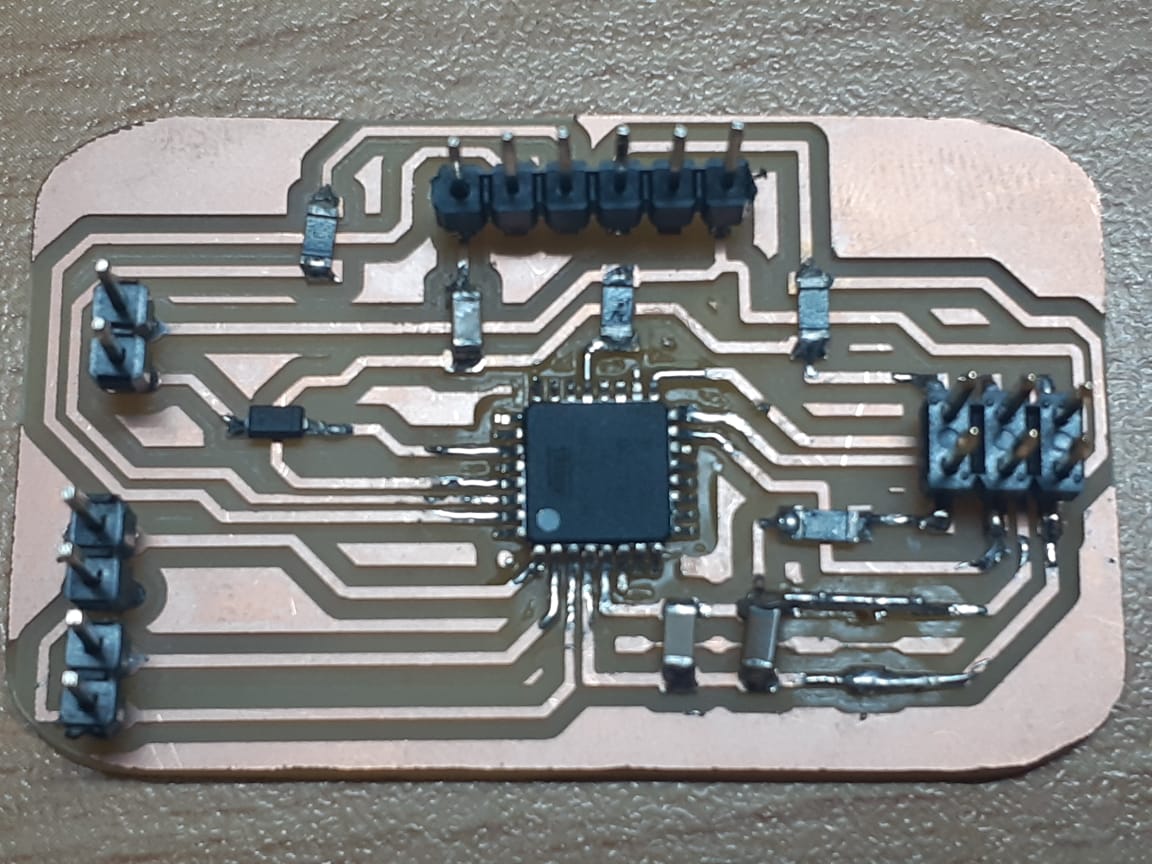
Atmega Board
I used an Atmega chip because it has a serial hardware. unlike Attiny chips which require us to define a software serial to use the communication, and that takes a huge amount of the processing memory.
For my final project, I need the DC motor as an input which requires two pins (groung and analog pin). And later on I will be using two output digital pins and a ground pin to connect the output devices.
I used pin A4 as analog input. and placed a diode between it and the board to guarantee that the signal will be only in one direction.
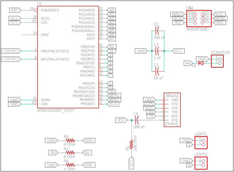
Notice that the schematic has no crystal. I will be using the enternal 8 MHz clock.
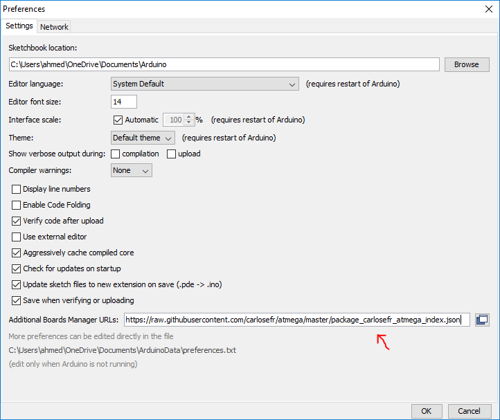
Programming the Atmega board goes the same way we did with the attiny. First we need to add the Atmega file by copying this URL into Arduino IDE's preferences.
https://raw.githubusercontent.com/carlosefr/atmega/master/package_carlosefr_atmega_index.json
Then install the files from the Boards Manager > Barebones Atmega Chips
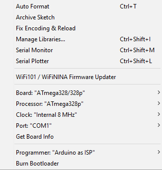
Select the tools as follows then burn the bootloader.
The first trial of burning the bootloader was not succesful, and after several attemps of diagnosing the problem and trying to program, it worked after removing the 10 uF capacitor and changing the Atmega chip with a new one.
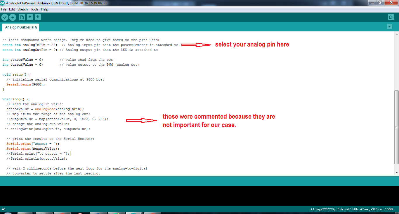
After burning the bootloader, I went to Files > Examples > Analog > AnalogInOutSerial. Then I changed the input pin from A0 to A4 and uploaded the code using a programmer.
After programming using Arduino as ISP, I disconnected the ISP cables and connected the board to the computer using the FDTI cable because it has the transmitter and reciever pins.
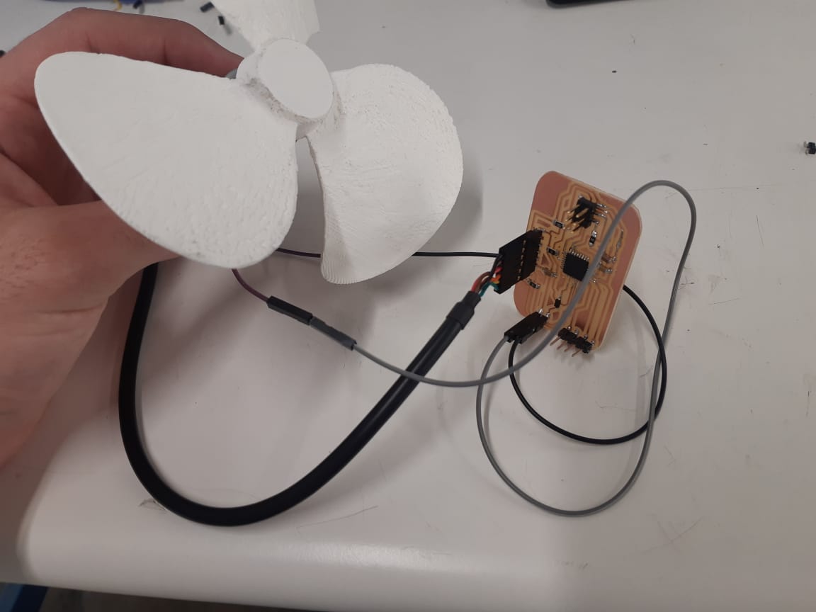
Finally, by openning the serial monitor, when the fan was still, the readings shown are all zero, but when it rotates the readings start increasing relatively with the rotational speed.
---
