


As a group, we are meant to build a machine that can fabricate something. And after a discussion, we agreed on building a wall painter; a simple device consists of two stepper mottors attached through a belt diagonally to a pen holder. The pen holder has a servo motor fastened to a slot with two pens. The components are to be connected to a controller board and programmed to read G-codes.
My task was to come up with an idea and create it, to hold the dawing pens and change them. Using the help of my collegues, we brainstormed ideas and sketches to come up with one good mechanism.
Mechanism Ideas:
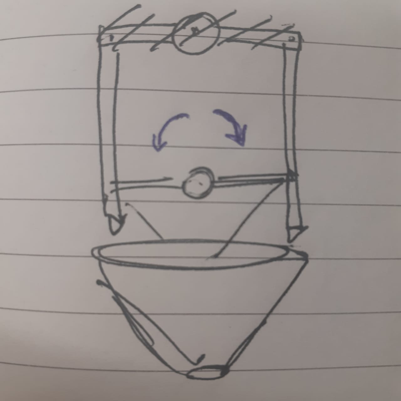
The idea of this sketch is to make a slot for the pens that the pen queued would drop inside it. The thought was inspired by the common multicoloured pens.
The problem with this design that, it would not be easily effecient and the ability to change the pens or control them might be tricky.
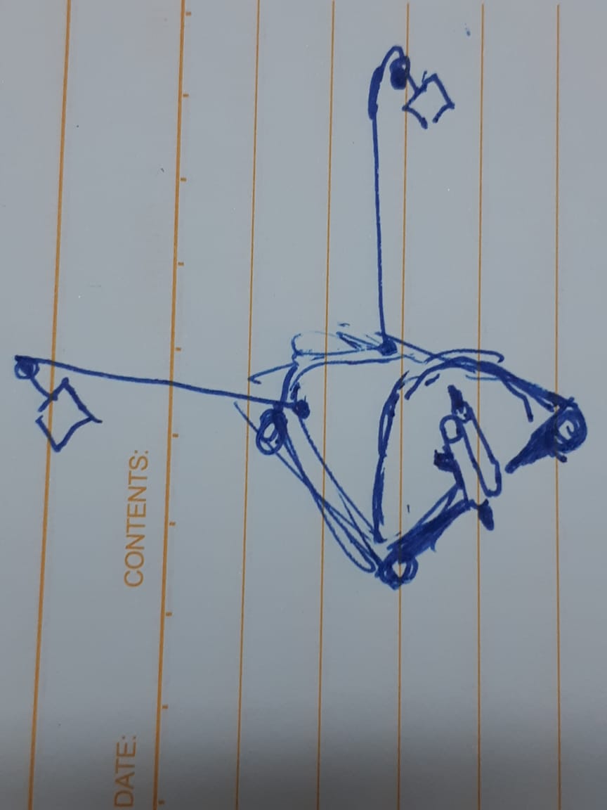
The second design is to attach the pens on a rotating disc, and the disc is to have an angle with the horizantle. This way, the only pen to touch the wall surface is the one in the lowest point, and when the disc rotates, this pen will change to another one.
The problem here is the complexity of the design, adn as we are pressured with the time, we searched for a yet easier design.
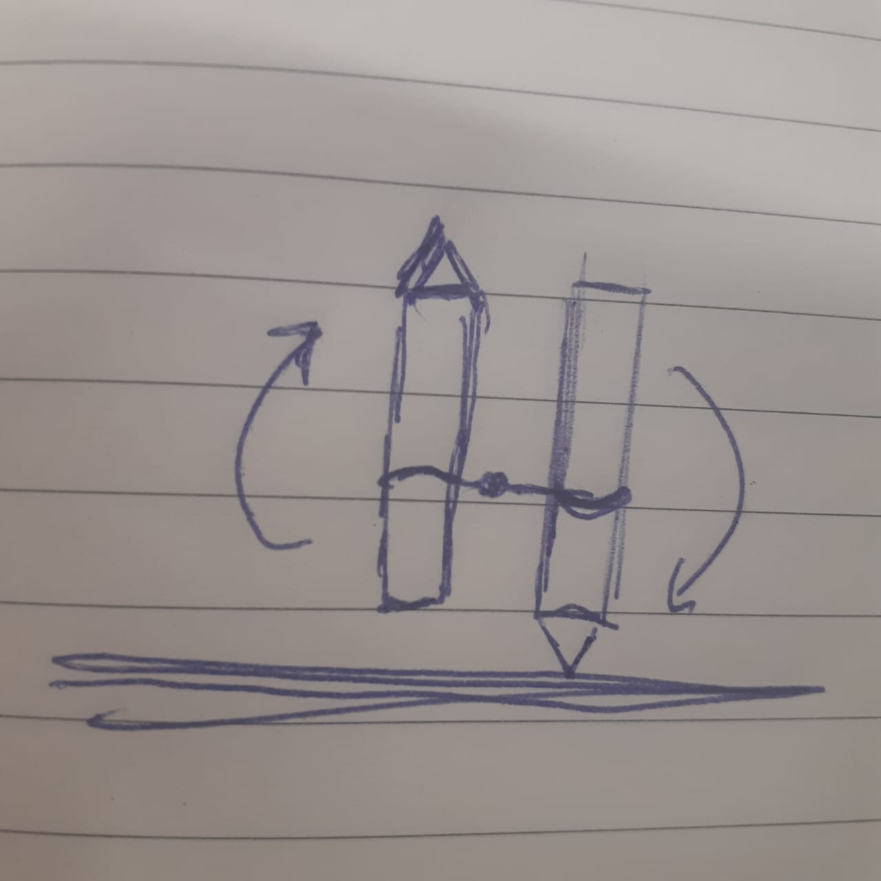
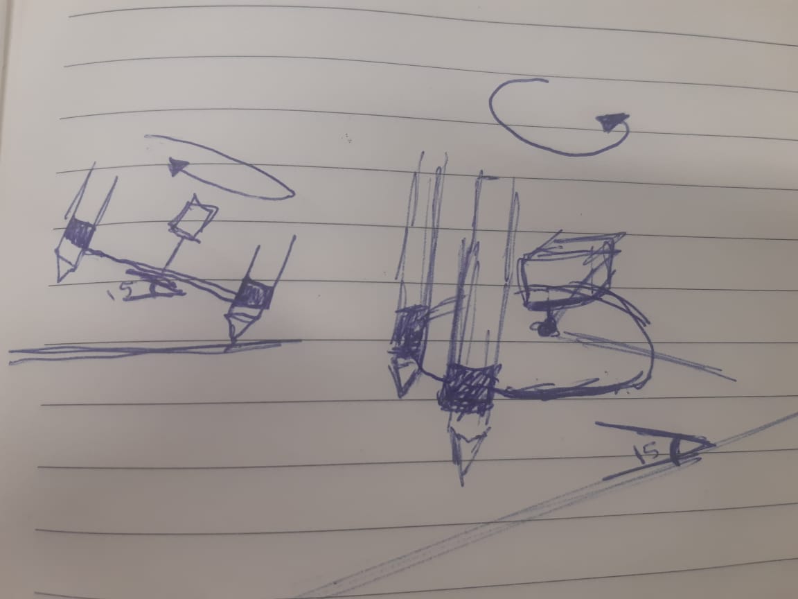
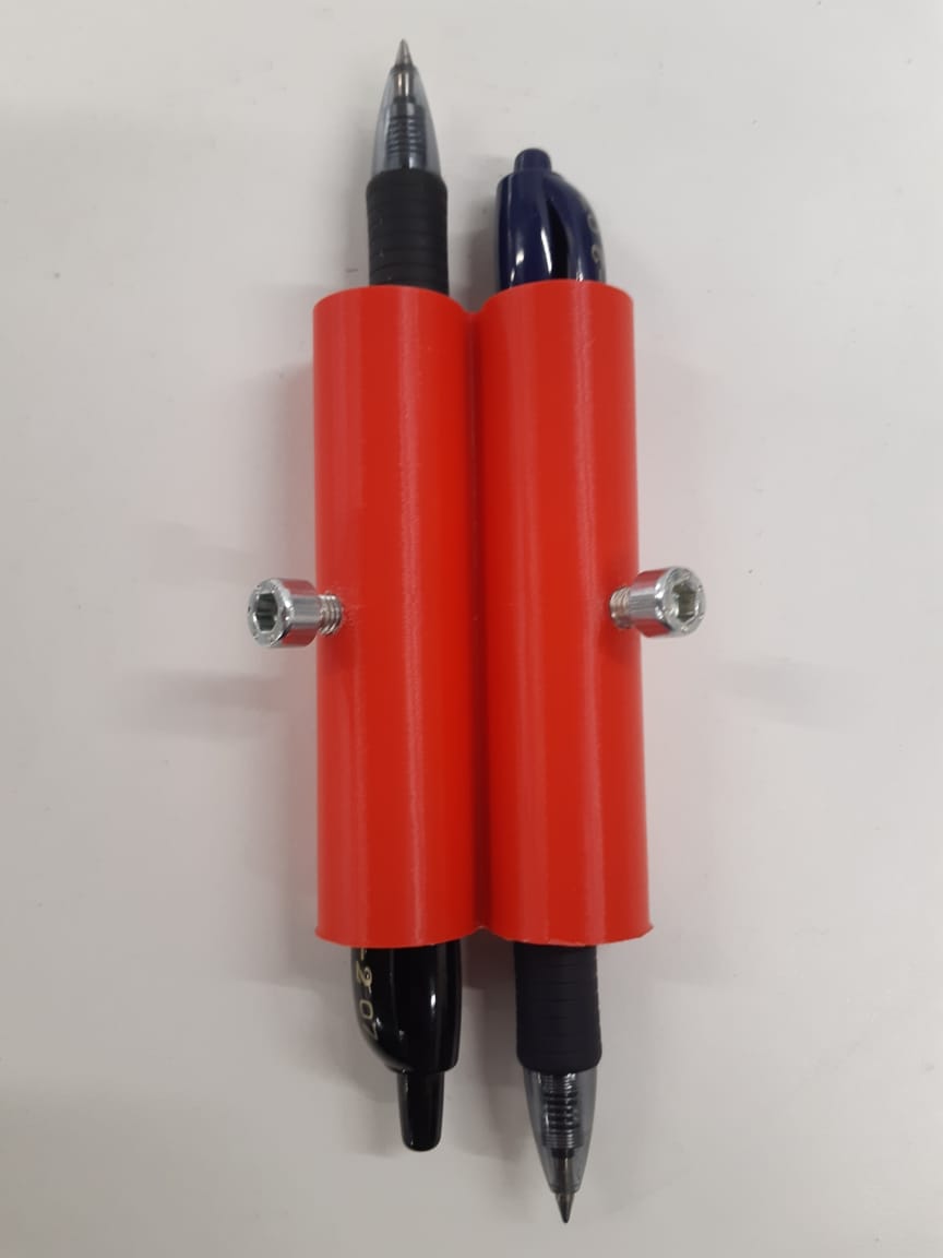
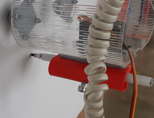
The last design is the one we went with. Two pens in an opposite direction, would be changed using a 180 degree servo motor.
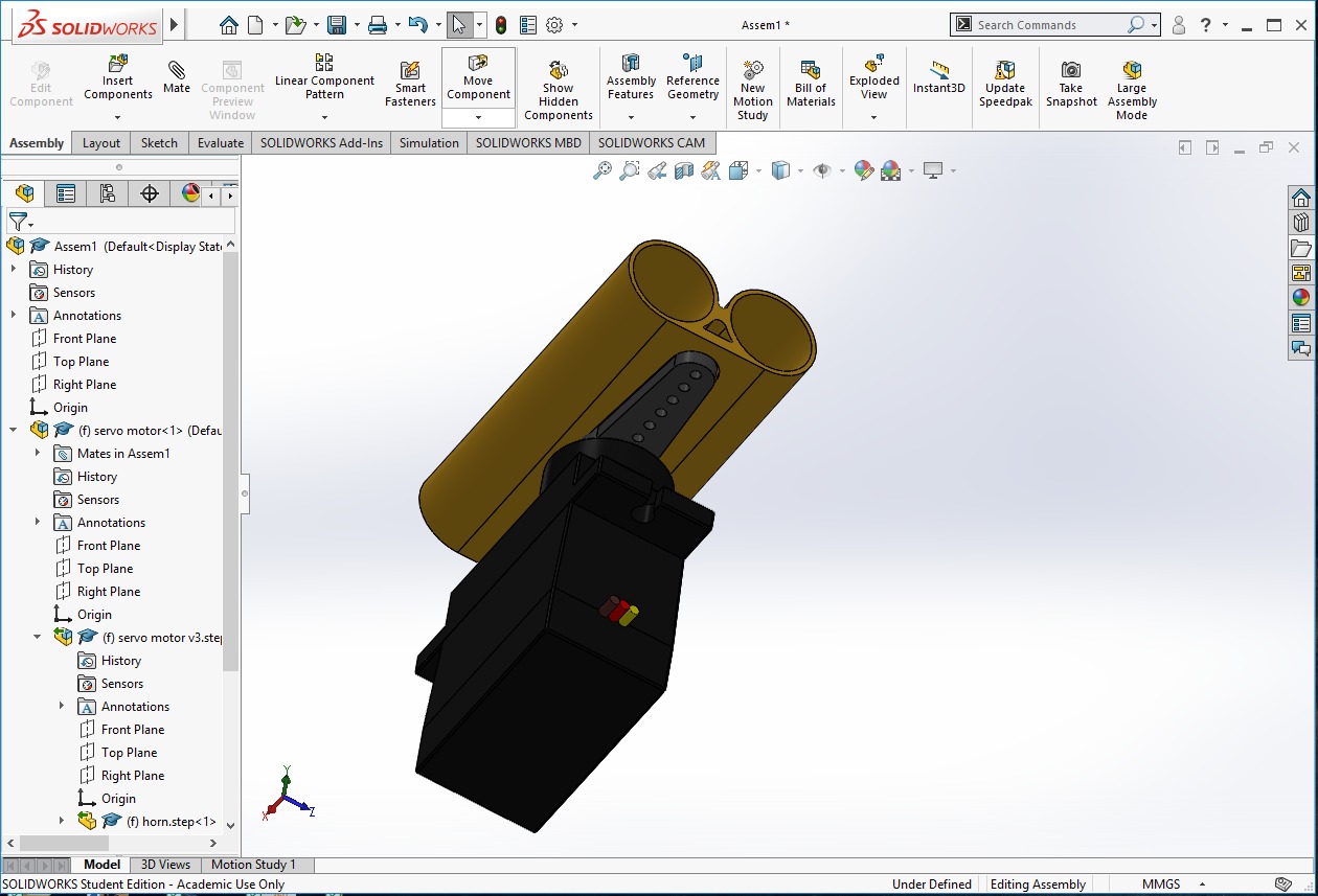
I made the parts design using Fusion 360, and then used SolidWorks as I prefer it for assembly.
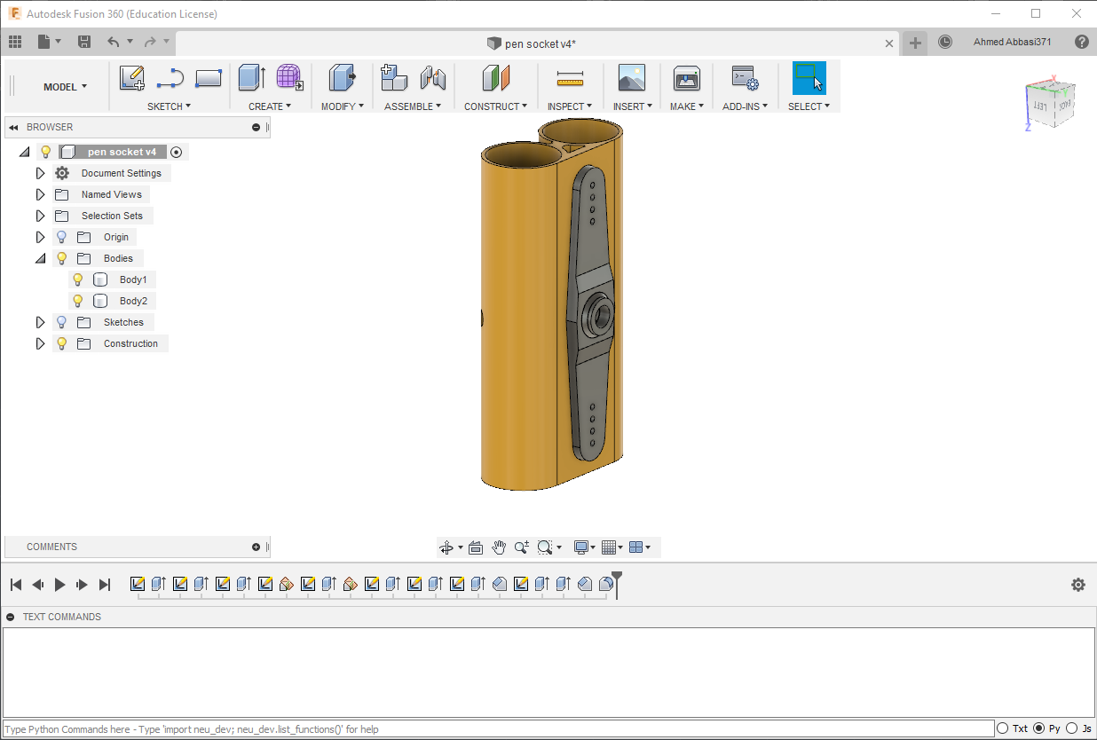
then manufactured them using 3D Printer.
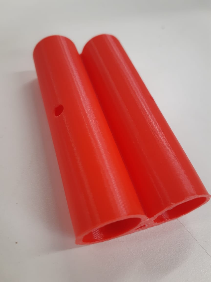
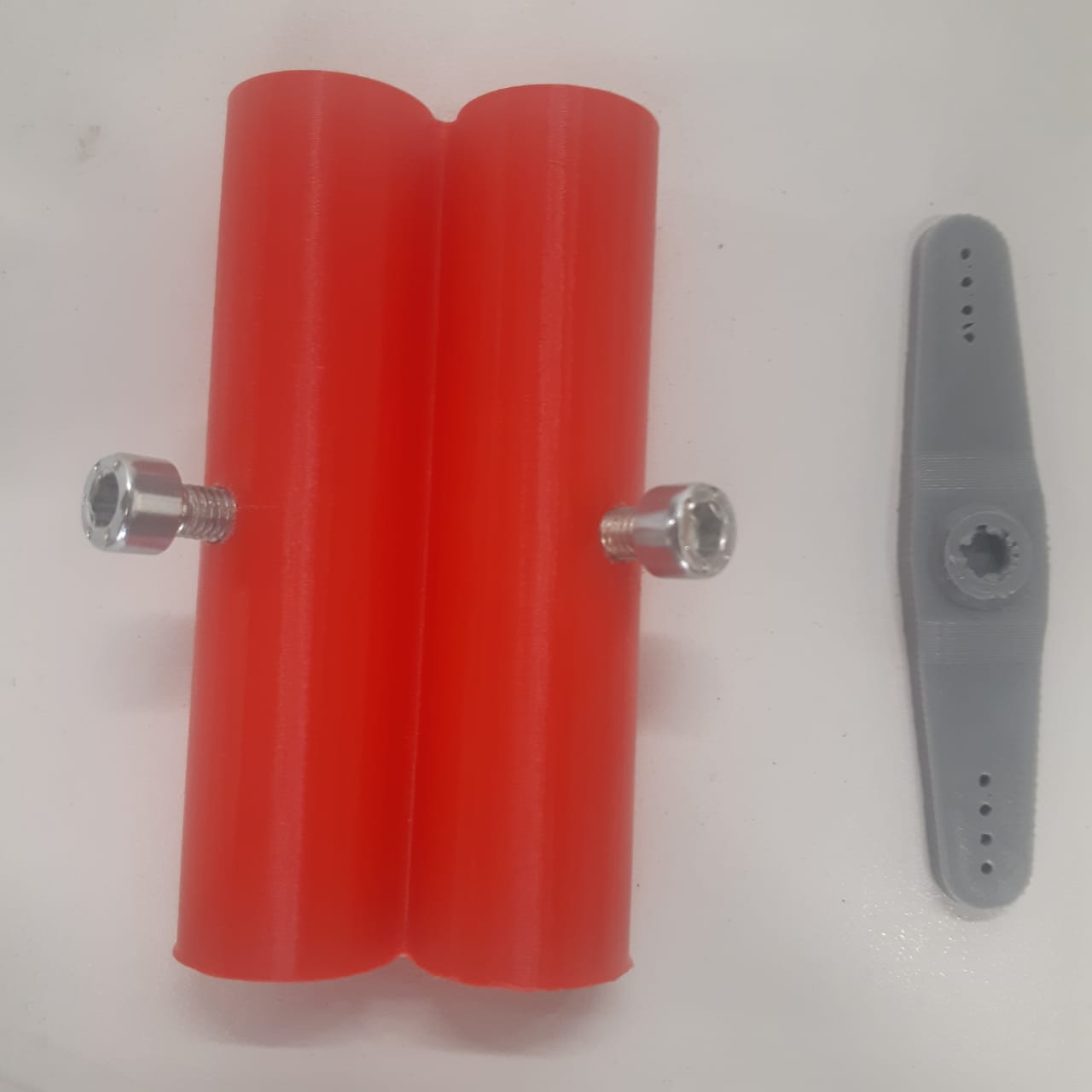
The pens are tried to be fastened to the holder, and the holder to the servo motor.
The servo motor's movement was tested as shown in the following video:
---
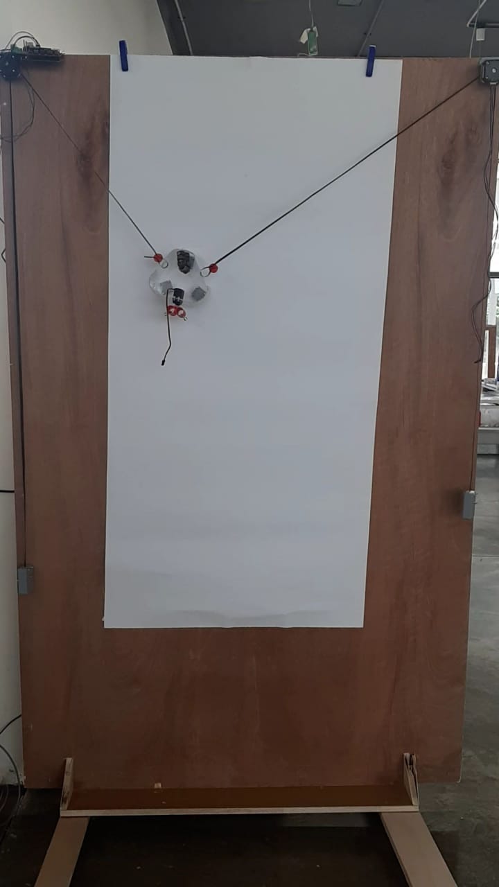
After the machine mechanical parts were assembled, it was time for wiring, programming, caliprating then testing the machine.
The movement of the machine depends on two stepper motors. We used a 6 wired hyprid steper motor.
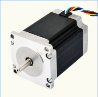
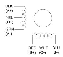
The fact that its hybrid, makes connecting the common leads optional. So we connected the four important wires to a shield holding two drivers, one for each stepper motor.
Our fear was that the stepper motors might not be able to left the weight of the printer, but they managed. The problem was that the belts were not tensioned to the gears on the motors which made the printing process not very accurate.
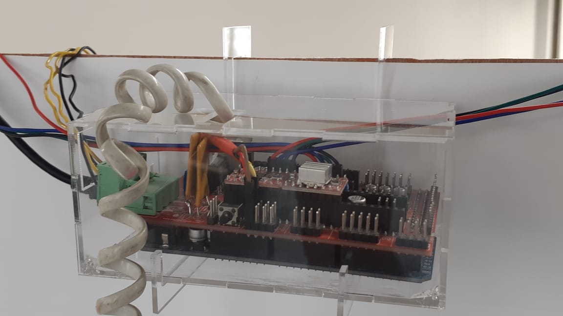
The servo was connected as well to the shield through a telephone cable, to make its movement easier without affecting the machine.
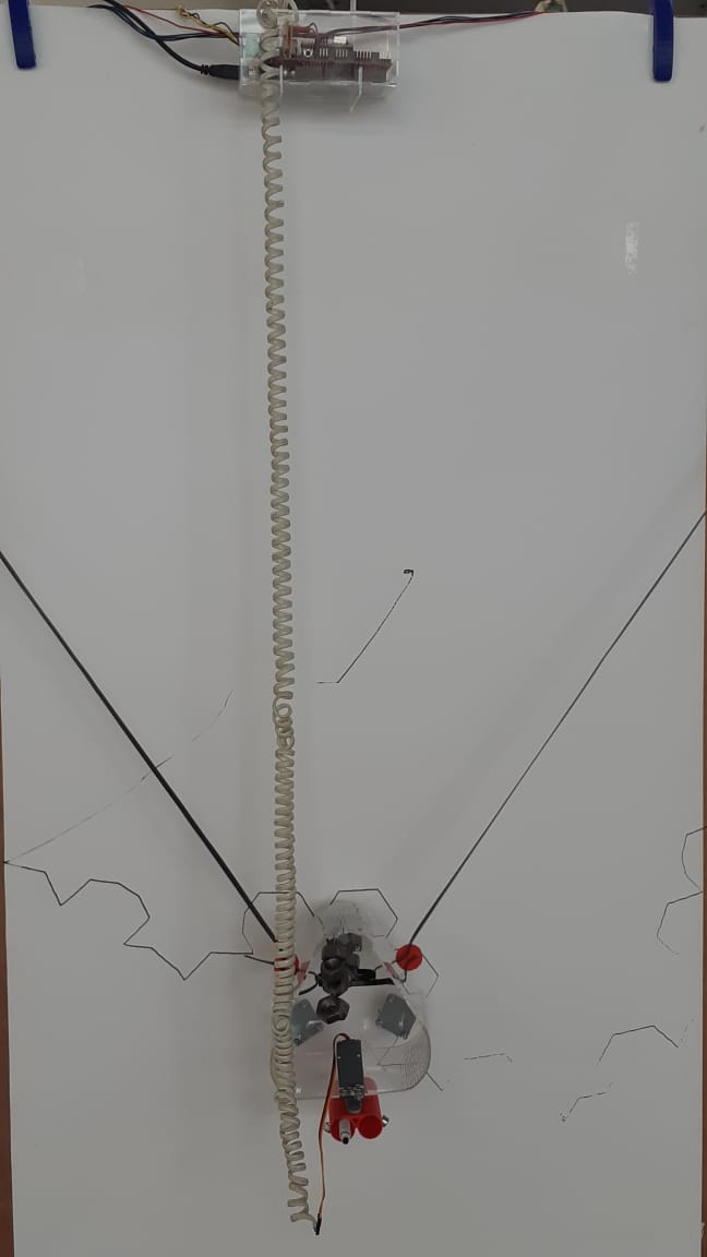
After multiple attemp to adjust the hanging weights as to create tension on the belts so they would move better with the motors rotation, and adjusting the G-codes and the initial starting point, we managed to make it print a sketch with acceptable accuracy.

However, adding the pen changing option to the G-codes was not accomplished yet, as we are still working on perfecting the machine functioality using one pen first.
---
To find more about our process in designing the machine, visit my colleagues documentations:
Hadil Tarek 