9. Embedded programming
Assignment
-
Group assignment Compare the performance and development workflows for other architectures
-
Individual assignment Read a microcontroller data sheet. Program your board to do something, with as many different programming languages and programming environments as possible.
Group Assignment
AVR data sheet
I read the AVR ATtiny44A datasheet and pick up some points that I am interested in.
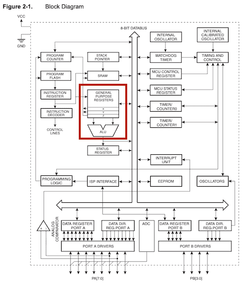
the AVR uses a Harvard architecture and the block diagram is as follows.
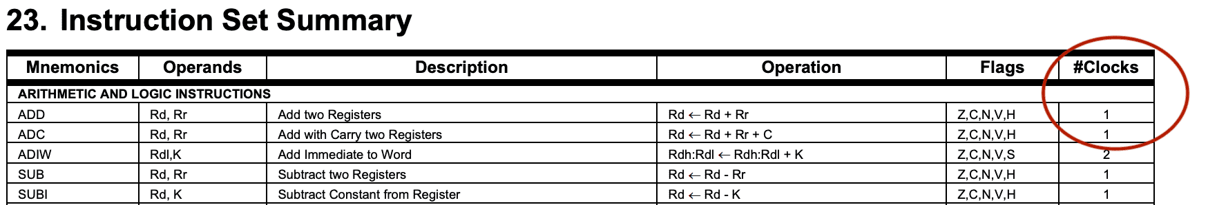
instruction execution cycle
Even the instruction that use two registers, the cycle is almost one clock.
 All 32 registers are directly connected to the Arithmetic Logic Unit (ALU),
 allowing two independent registers to be accessed in one single instruction
 executed in one clock cycle.
So I examined the instructions and confirmed that clock of instruction that use two registers is one clock as follows.
I checked information of other AVR peripherals.
Clock system
There are many clock source options and the selected source is input to the clock generator. The clock source are used to many modules such as timer, cpu, flash, ADC and I/o.
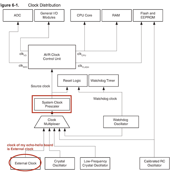
I reffered the code example of clock setting in the hello.echo board c. First set the CLKPCE bit to enable Prescaler, then set clock parameters. It is combination of CLKPS0 - 3.
// set clock divider to /1
   //
   CLKPR = (1 << CLKPCE);
   CLKPR = (0 << CLKPS3) | (0 << CLKPS2) | (0 << CLKPS1) | (0 << CLKPS0);
//
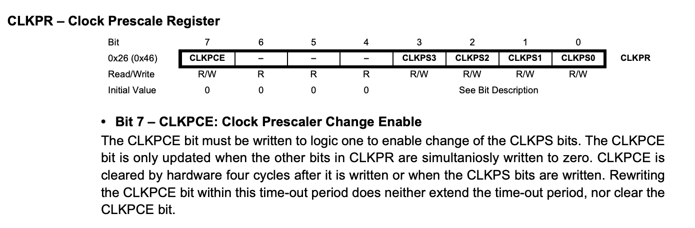

System Clock Prescaler The ATtiny24A/44A/84A system clock can be divided by setting the “CLKPR – Clock Prescale Register” on page 31. This feature can be used to decrease power consumption when the requirement for processing power is low. This can be used with all clock source options, and it will affect the clock frequency of the CPU and all synchronous peripherals. clkI/O, clkADC, clkCPU, and clkFLASH are divided by a factor as shown in Table 6-11 on page 32.
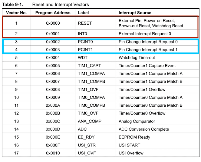
interrupt
The priority of interrupts is as follows. Reset is the 1st priority, and the second is External interrupt INT0. PCINT0 and PCINT1 are Pin change interrupt.
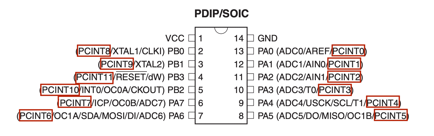
It is able to use all PA/PB port pins as interrupt PCINTxx.
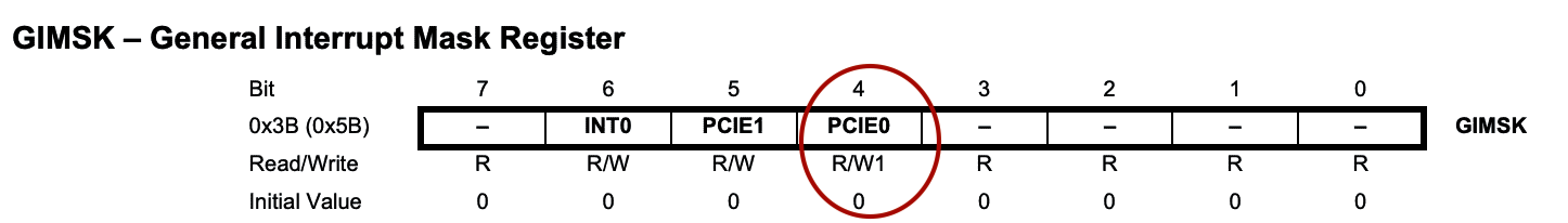
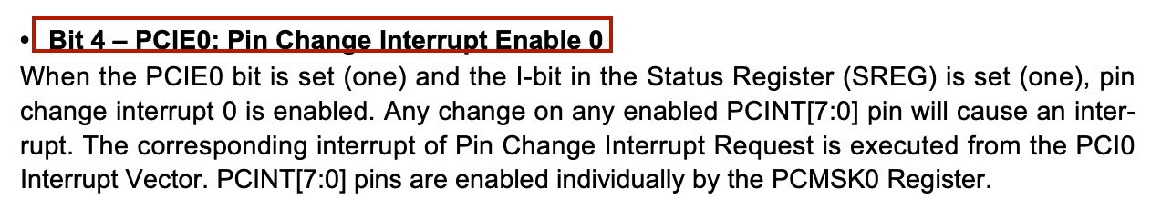
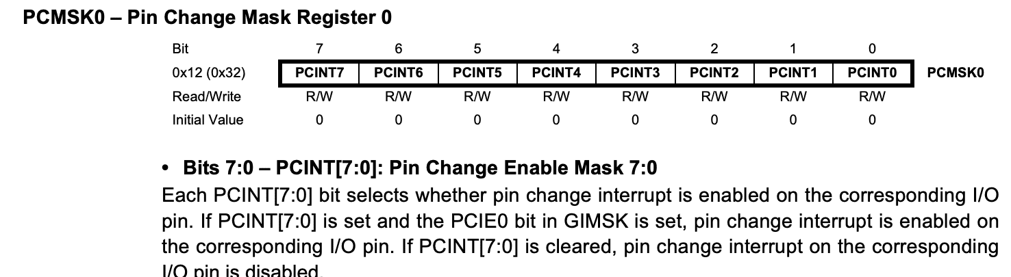
I reffered the code example of intereupt in the hello.echo board c. The flow is three steps. First enable the pin change interrupt by GIMSK PCIE0 bit, then define the interrupt pin with PCMSK0 or PCMSK1. After that enable the interrupt by sei().
#define serial_interrupt (1 << PCIE0)
#define serial_interrupt_pin (1 << PCINT0)


// set up pin change interrupt on input pin
   //
   set(GIMSK, serial_interrupt);
   set (PCMSK0, serial_interrupt_pin);
   sei();
I/O Ports
Port A is a 8-bit bi-directional I/O port and Port B is 4-bit. Internal pull-up exists for each port, and it is selectable. Port A has alternate functions such as ADC, timer/counter,SPI and pin change interrupt. Port B also has special functions such as Crystal Oscillator I/O, Reset,and pin change interrupt.
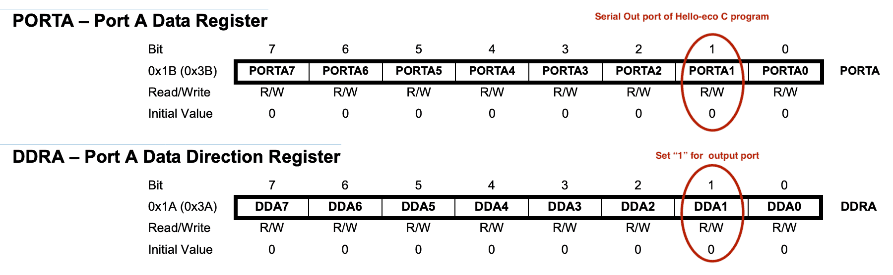
I reffered the code example of port initialization in the hello.echo board c.
#define serial_port PORTA
#define serial_direction DDRA
#define serial_pin_out (1 << PA1)

 // initialize output pins
 //
   set(serial_port, serial_pin_out);
   output(serial_direction, serial_pin_out);
 //
To initialize an output pin, set the direction with DDRA, then set the data to Data register.
As for input port, the initialization is not necessary, because the initial direction of port is input. To read the input port, we have to use PINx instead of PORTx.
I found a useful function that toggle the pin. Output data should be stored to PORTx, however if write “1” to PINx, the output value toggles, independent on the value of DDRx.
C program
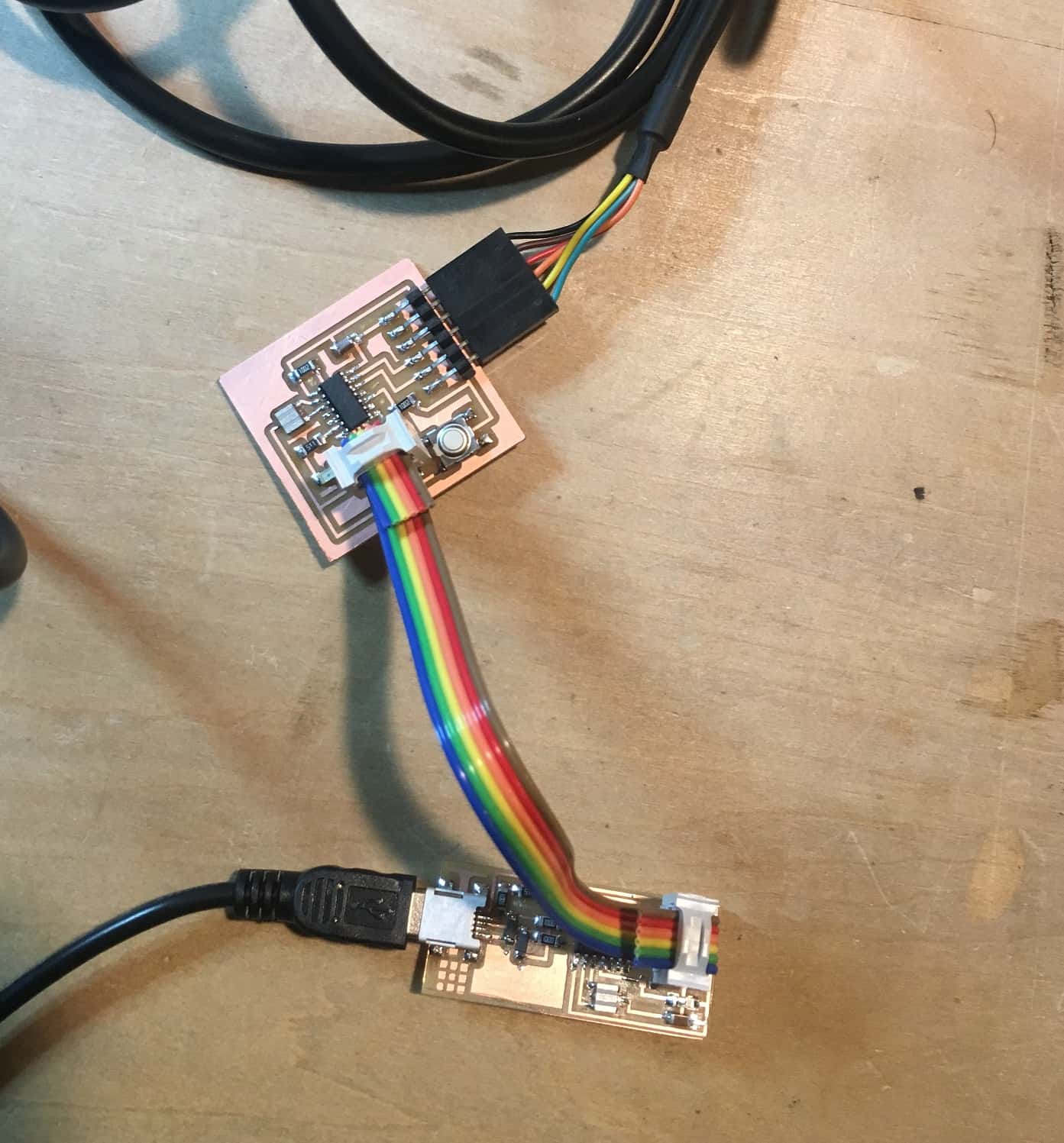
I read through the hello.echo board c program, then programmed a simple code for my week#7 board. I used Fab ISP board I created at week#7 for the programming. I referred the sequence and did compile, fuse and program.
First one is simple LED ON/OFF program. The LED blinks by 1000ms interval.
//----------------------------------------------------------------------------------------------------
//  LED1.c       Led blink test
//----------------------------------------------------------------------------------------------------
#include <avr/io.h>
#include <util/delay.h>
#include <avr/pgmspace.h>

#define led_port PORTA
#define led_pins PINA
#define led_pin_out (1 << PA7)
#define led_direction DDRA


//----------------------------------------------------------------------------------------------------
//      main
//----------------------------------------------------------------------------------------------------
void main(void) {

   //--------  set clock divider to /1 ---------------------------

   CLKPR = (1 << CLKPCE);
   CLKPR = (0 << CLKPS3) | (0 << CLKPS2) | (0 << CLKPS1) | (0 << CLKPS0);

   //-------- initialize output pins -----------------------------

    led_port |= led_pin_out;            // set led port
    led_direction |= led_pin_out;    // set led port direction

   //-------- Loop  -----------------------------------------------

    while(1){
        led_port |= led_pin_out;            // led on
        _delay_ms(1000);    //wait for 1000 ms
        led_port &= (~led_pin_out);             // led off
      _delay_ms(1000);    //wait for 1000 ms
    }
}
Second one is combination of tact switch on the board. I changed to toggle LED by the tact switch and considered chattering of the tact switch. The switch input is judged in two decisions.
//----------------------------------------------------------------------------------------------------
//  LED2.c       Led blink test
//----------------------------------------------------------------------------------------------------
#include <avr/io.h>
#include <util/delay.h>
#include <avr/pgmspace.h>

#define led_port PORTA
#define led_pin_out (1 << PA7)
#define led_direction DDRA
#define led_togglePins PINA

//#define sw_port PORTA
#define sw_pins PINA
#define sw_pin  (1 << PA3)


//----------------------------------------------------------------------------------------------------
//      main
//----------------------------------------------------------------------------------------------------
void main(void) {

   //--------  set clock divider to /1 ---------------------------

   CLKPR = (1 << CLKPCE);
   CLKPR = (0 << CLKPS3) | (0 << CLKPS2) | (0 << CLKPS1) | (0 << CLKPS0);

   //-------- initialize output pins -----------------------------

    led_port |= led_pin_out;            // set led port
    led_direction |= led_pin_out;     // set led port direction

   //-------- Loop  -----------------------------------------------

    while(1){
//      chkSw();
        chkSw2();

    }
}

//----------------------------------------------------------------------------------------------------
//      sw read 1
//----------------------------------------------------------------------------------------------------
void chkSw(void){

    if(sw_pins & sw_pin){
                led_port &= ~led_pin_out;           // led off
    }else{
                led_port |= led_pin_out;            // led on
    }
}

//----------------------------------------------------------------------------------------------------
//      sw read 2
//----------------------------------------------------------------------------------------------------
void chkSw2(void){

    if(sw_pins & sw_pin){
             //   led_port &= ~led_pin_out;             // led off
    }else{
         _delay_ms(10);    //wait for 10 ms
        if(sw_pins & sw_pin){
                led_togglePins |= led_pin_out;          // led toggle
        }
    }
}
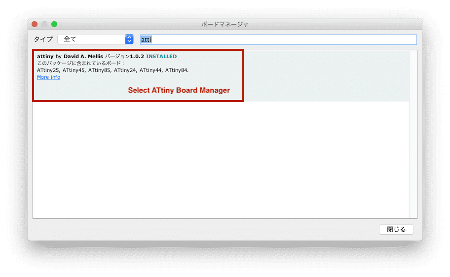
Arduino
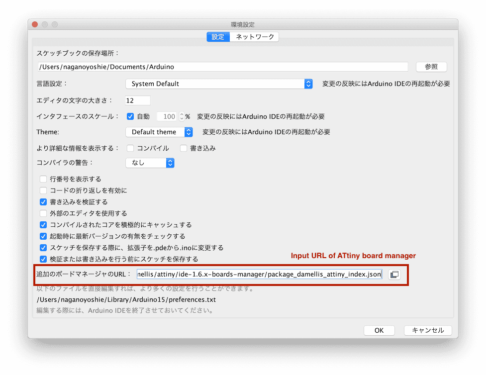
First I set Arduino IDE for ATtiny.
- install the ATtiny support using the built-in boards manager.
-
Open preference then paste the following URL into the field and click OK https://raw.githubusercontent.com/damellis/attiny/ide-1.6.x-boards-manager/package_damellis_attiny_index.json
-
install the ATtiny support using the built-in boards manager.
I confirmed the pin mapping of Arduino and ATtiny with the following information.
Before the Arduino programming, I checked the chattering wave with a oscilloscope. I assumed the maximum width is 10ms at C code, but it seemed around 2ms at the Oscilloscope wave form. So I adjusted the code as follows. Check the level three times with 1ms interval. I tried several parameters. The condition of 1<val might be severe, but it seems fine for the board.
//--------------------------------------------
// ATtiny44 LED Test   Mar.16, 2019
//--------------------------------------------


const int ledPin = 8;
const int swPin = 7;

void setup() {
 pinMode(ledPin, OUTPUT);
 pinMode(swPin, INPUT);
 digitalWrite(ledPin, LOW);

}

//--------------------------------------------
// Main Loop
//--------------------------------------------

void loop() {

 int ledState = chkSw();

 if(ledState){
    digitalWrite(ledPin,HIGH);
 }else{
    digitalWrite(ledPin,LOW);
 }

}

//--------------------------------------------
// Check tact sw status
//--------------------------------------------

 int chkSw(){

  int val=0;
  int state=0;

  for(int i=0; i<3; i++){     // Chattering
    val += digitalRead(swPin);
    delay(1);
  }

  if(val <1){
    state = 1;
  }
       return(state);
 }
Learning outcomes
-
I used to use net information without reading Datasheet, but it turned out that Datasheet contains useful information about special usage as well as standard usage. In particular register description of each Feature is important for development.
-
There are many clock sources and their settings. I tried only one option this time, but I would like to explore it when developing an application which needs severe timing control.
-
I learned how to control each port using C language bit operation without affecting other ports.
-
I learned how to program ATTiny using Arduino IDE. I am familiar with the Arduino IDE, so I can develop simple apps in a short time. However, I learned that the size of the Arduino library is versatile and large, so it is important to select the language according to the memory of microcontroller and schedule of the project.