12. Output devices
Assignment
-
Group assignment
Measure the power consumption of an output device -
Individual assignment Add an output device to a microcontroller board you’ve designed and program it to do something
Group Assignment
Planning and Research
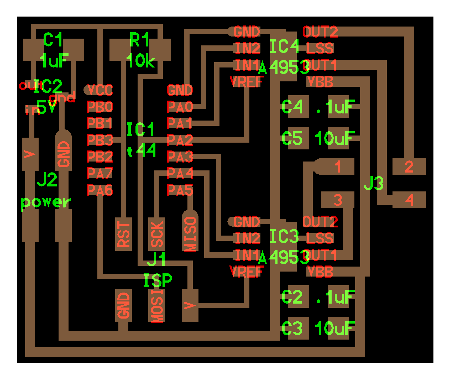
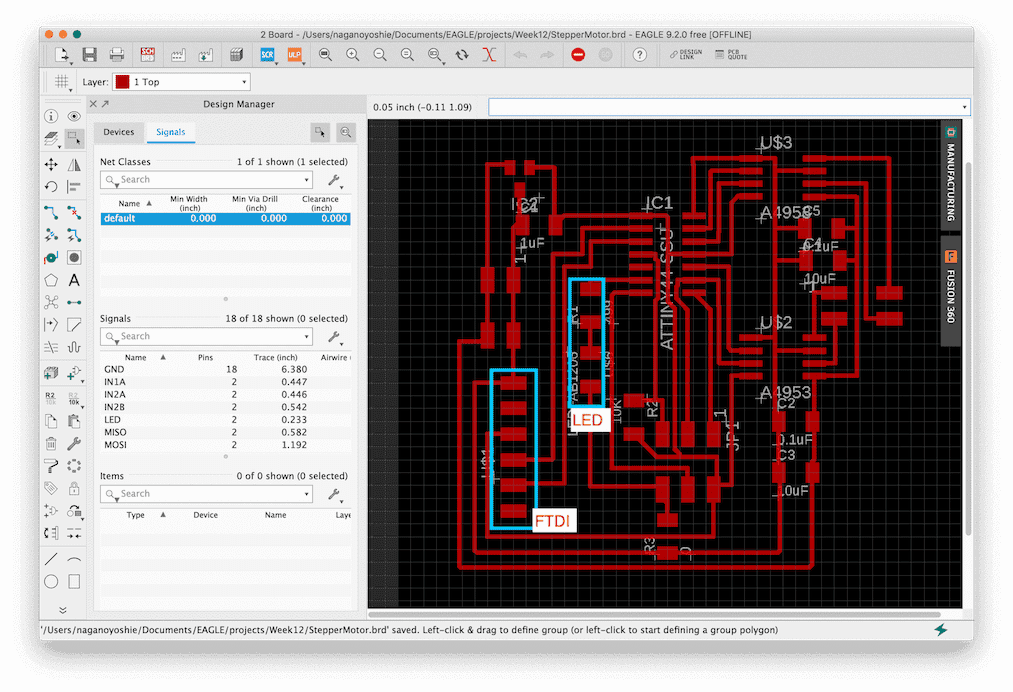
My plan is to use stepper motor (bipolar) for my board. It might be used for my final project to move mist tube. Based on the example, I customized to add LED as output device, and FTDI to communicate with application.
Board example
The difference between unipolar and bipolar is:
-
Unipolar
- Use half of the motor coil and switch the coil polarity(N/S) depending of current flow.
- There are few switch parts and the sequence is simple
- The operating efficiency of the motor coil is low
-
Bipolar
- Switches the direction of the coil by switching the direction of the current supplied to the motor coil.
- There are many switch parts and the sequence is complicated
- Efficiency of motor coil is high
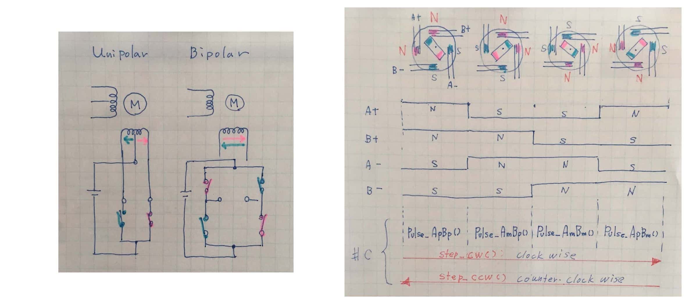
- Motor Control The motor control sequence (above right image) corresponds to the function oc C code. In case of clockwise step, the sequence is from left to right, the function call is Pulse_ApBp() > Pulse_AmBp() > Pulse_AmBm() > PulseApBm(). In case of counter clockwise step, the sequence is opposite, from right to left.
Parts List
| parts | description | number |
|---|---|---|
| bipolar stepper motor | SM-42BYG011-25-1209 | 1 |
| micro controller | ATTiny 44 | 1 |
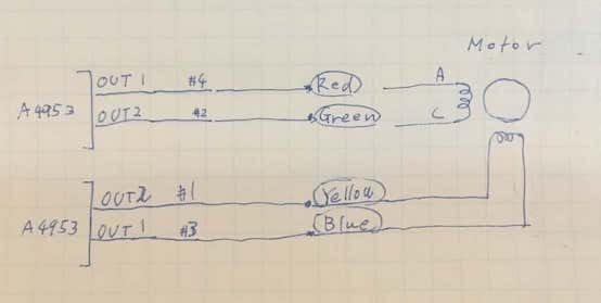
| motor driver | A4953 | 2 |
| capacitor | 1uF | 1 |
| capacitor | 10uF | 2 |
| capacitor | 0.1uF | 2 |
| resistor | 10KΩ | 2 |
| resistor | 499 | 1 |
| resistor | 0KΩ | 1 |
| led | red | 1 |
| header | 6pin for FTDI | 1 |
| header | 6pin for ISP | 1 |
| header | 4pin for power | 1 |
| header | 4pin for motor | 1 |
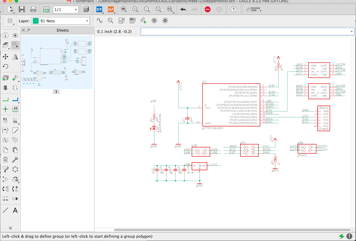
Design
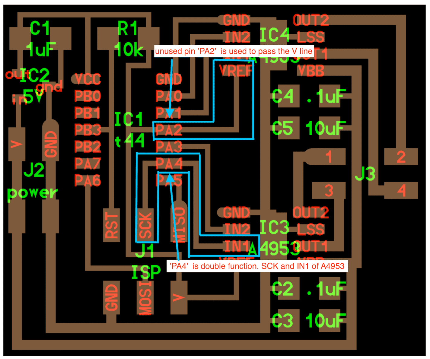
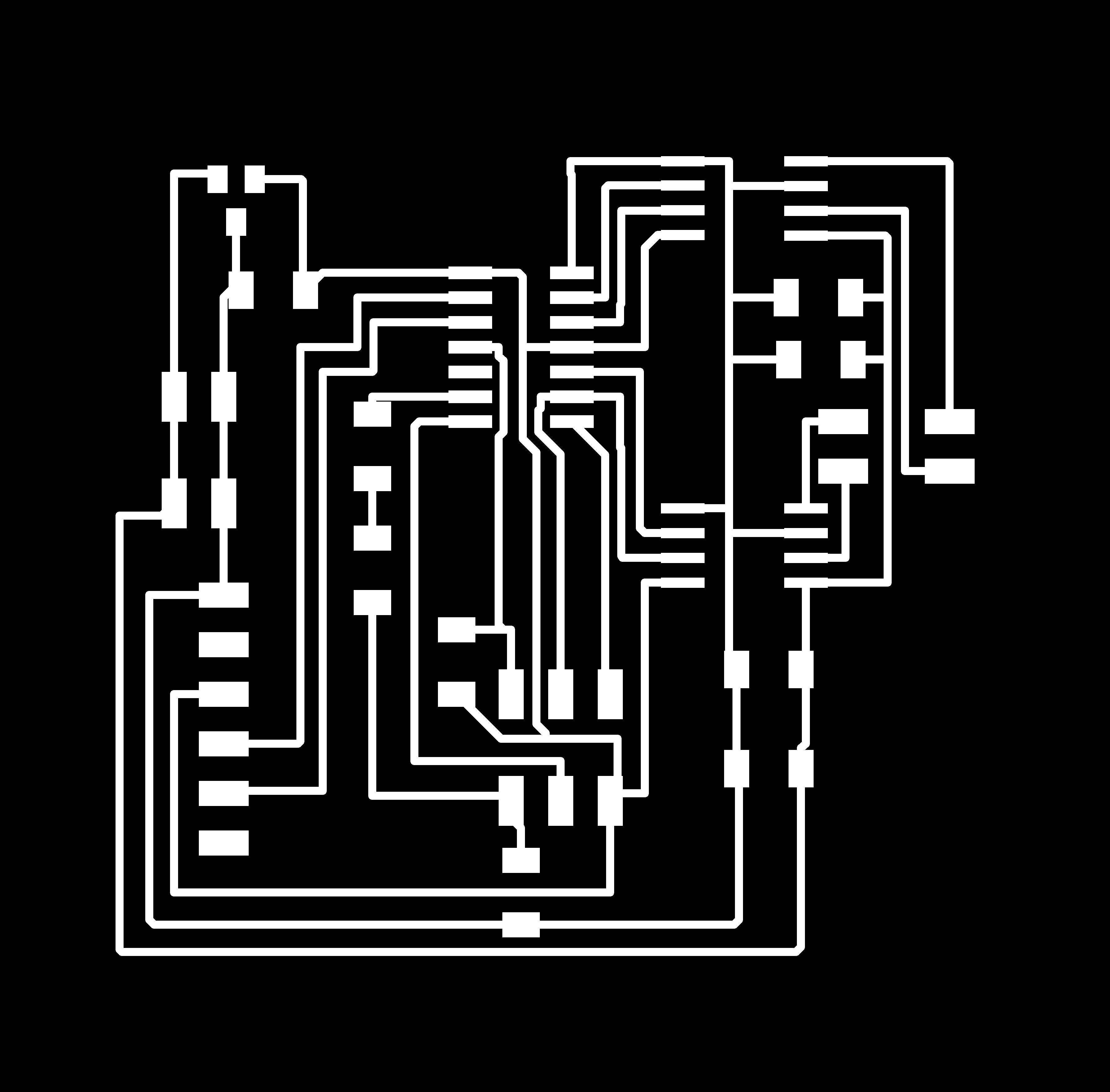
I designed the board with Eagle.
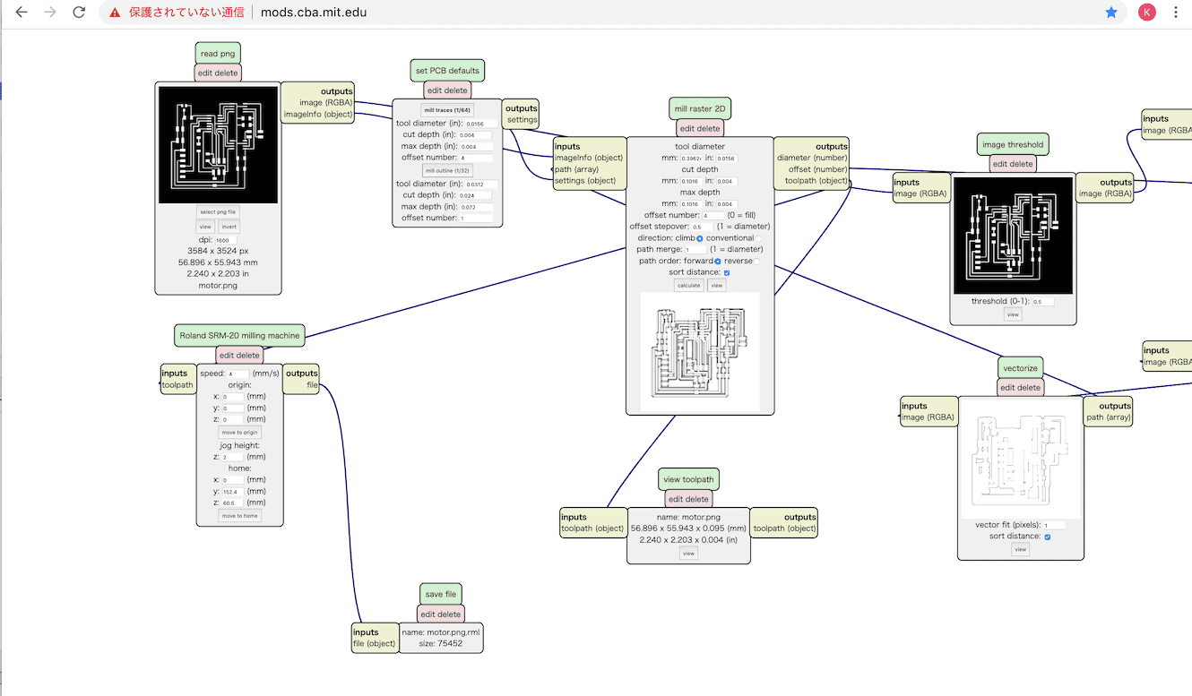

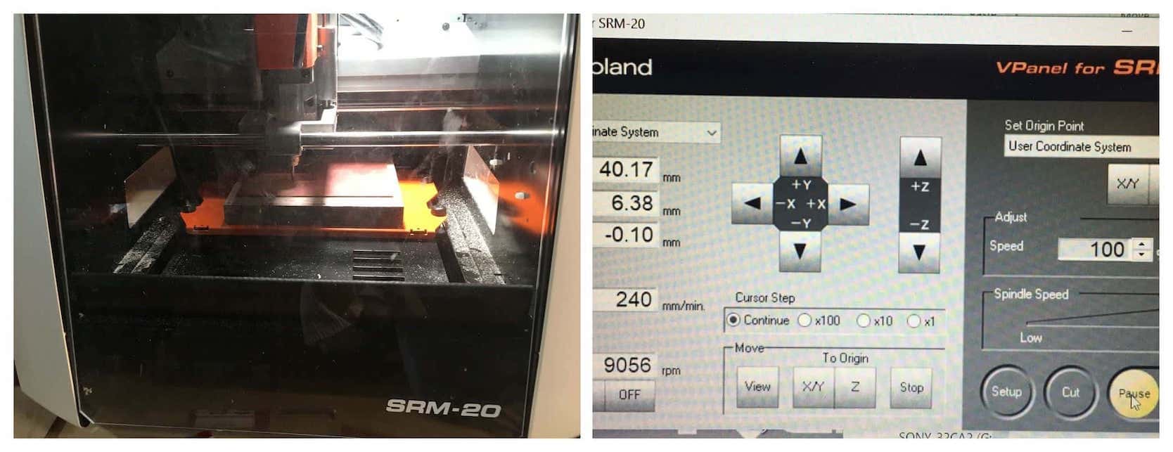
Milling
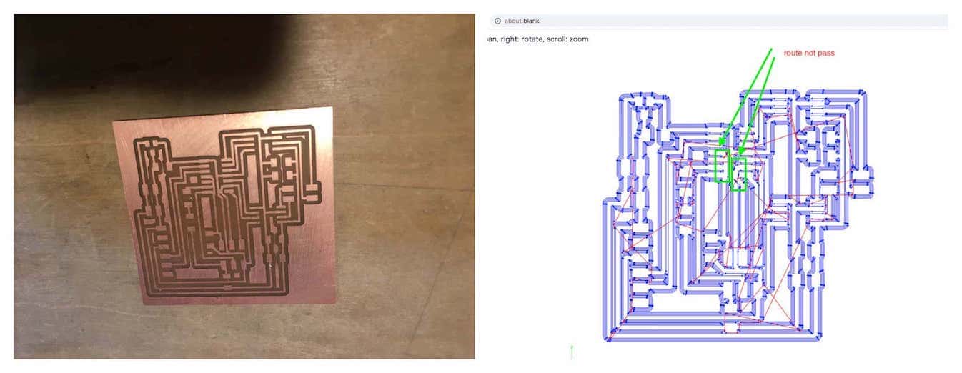
I milled the board using SRM-20 and soldered the parts.
After soldering all parts, I found the path problem. The green area were not routed properly. To fix it, I removed ATtiny44 and cut the route using Ultra sonic cutter.
Connection between board and motor:
C programming
I read the AVR ATtiny44A datasheet and Neil’s C code.
In case of clock wise rotation, the function below is called.
// clockwise step
//
void step_cw() {
   pulse_ApBp();
   pulse_AmBp();
   pulse_AmBm();
   pulse_ApBm();
   }
//
It corresponds to the flow of left to right in the right image.
The first movement, A+ and B+ = N, corresponds to the function below.
//
// A+ B+ PWM pulse
//
void pulse_ApBp() {
  clear(bridge_port, A2);
  clear(bridge_port, B2);
  set(bridge_port, A1);
  set(bridge_port, B1);
   for (count = 0; count < PWM_count; ++count) {
      set(bridge_port, A1);
      set(bridge_port, B1);
      on_delay();
      clear(bridge_port, A1);
      clear(bridge_port, B1);
      off_delay();
      }
   }
//
And the next movement, B+ and A- = N, corresponds to the function below.
void pulse_AmBp() {
  clear(bridge_port, A1);
  clear(bridge_port, B2);
  set(bridge_port, A2);
  set(bridge_port, B1);
   for (count = 0; count < PWM_count; ++count) {
      set(bridge_port, A2);
      set(bridge_port, B1);
      on_delay();
      clear(bridge_port, A2);
      clear(bridge_port, B1);
      off_delay();
      }
   }
//
In case of counter clock wise movement, call the functions in opposite order.
Simple motor control
First I programmed simple motor control program to output pwm signal. Before connecting the stepper motor, I measured the output pin of A4953 using oscilloscope. Signals like pwm was outputted though the ground line was very noisy.

The function below is called from main loop.
- Clockwise step with LED On
- Counter Clockwise step with LED Off
void motorTest(){
   static uint8_t i;

   for (i = 0; i < step_count; ++i) {
            step_cw();
            led_port |= led_pin_on;             // led on
    }

    for (i = 0; i < step_count; ++i) {
            step_ccw();
            led_port &= ~led_pin_on;             // led off
    }
}
C code:
#include <avr/io.h>
#include <util/delay.h>
#include <avr/pgmspace.h>


#define output(directions,pin) (directions |= pin) // set port direction for output
#define set(port,pin) (port |= pin) // set port pin
#define clear(port,pin) (port &= (~pin)) // clear port pin
#define pin_test(pins,pin) (pins & pin) // test for port pin
#define bit_test(byte,bit) (byte & (1 << bit)) // test for bit set

#define bridge_port PORTA // H-bridge port
#define bridge_direction DDRA // H-bridge direction
#define A2 (1 << PA0) // H-bridge output pins
#define A1 (1 << PA1) // "
#define B2 (1 << PA3) // "
#define B1 (1 << PA4) // "
//#define on_delay() _delay_us(35) // PWM on time
#define on_delay() _delay_us(25) // PWM on time

//#define off_delay() _delay_us(15) // PWM off time
#define off_delay() _delay_us(5) // PWM off time
#define PWM_count 100 // number of PWM cycles
//#define step_count 20 // number of steps
#define step_count 200 // number of steps

//---------------------------------------------

#define serial_port PORTB
#define serial_direction DDRB
#define serial_pin_out (1 << PB1)   //week12


//---------------------------------------------
#define led_port PORTA
#define led_pin_out (1 << PA7)
#define led_direction DDRA
#define led_pin_on (1 << PA7)

//---------------------------------------------

static uint8_t count;

//
// A+ B+ PWM pulse
//
void pulse_ApBp() {
  clear(bridge_port, A2);
  clear(bridge_port, B2);
  set(bridge_port, A1);
  set(bridge_port, B1);
   for (count = 0; count < PWM_count; ++count) {
      set(bridge_port, A1);
      set(bridge_port, B1);
      on_delay();
      clear(bridge_port, A1);
      clear(bridge_port, B1);
      off_delay();
      }
   }
//
// A+ B- PWM pulse
//
void pulse_ApBm() {
  clear(bridge_port, A2);
  clear(bridge_port, B1);
  set(bridge_port, A1);
  set(bridge_port, B2);
   for (count = 0; count < PWM_count; ++count) {
      set(bridge_port, A1);
      set(bridge_port, B2);
      on_delay();
      clear(bridge_port, A1);
      clear(bridge_port, B2);
      off_delay();
      }
   }
//
// A- B+ PWM pulse
//
void pulse_AmBp() {
  clear(bridge_port, A1);
  clear(bridge_port, B2);
  set(bridge_port, A2);
  set(bridge_port, B1);
   for (count = 0; count < PWM_count; ++count) {
      set(bridge_port, A2);
      set(bridge_port, B1);
      on_delay();
      clear(bridge_port, A2);
      clear(bridge_port, B1);
      off_delay();
      }
   }
//
// A- B- PWM pulse
//
void pulse_AmBm() {
  clear(bridge_port, A1);
  clear(bridge_port, B1);
  set(bridge_port, A2);
  set(bridge_port, B2);
   for (count = 0; count < PWM_count; ++count) {
      set(bridge_port, A2);
      set(bridge_port, B2);
      on_delay();
      clear(bridge_port, A2);
      clear(bridge_port, B2);
      off_delay();
      }
   }
//
// clockwise step
//
void step_cw() {
   pulse_ApBp();
   pulse_AmBp();
   pulse_AmBm();
   pulse_ApBm();
   }
//
// counter-clockwise step
//
void step_ccw() {
   pulse_ApBm();
   pulse_AmBm();
   pulse_AmBp();
   pulse_ApBp();
   }

//-------------------------
void motorTest(){
   static uint8_t i;

   for (i = 0; i < step_count; ++i) {
            step_cw();
            led_port |= led_pin_on;             // led on
    }

    for (i = 0; i < step_count; ++i) {
            step_ccw();
            led_port &= ~led_pin_on;             // led off
    }
}

int main(void) {
   //
   // main
   //
   static uint8_t i,j;
   //
   // set clock divider to /1
   //
   CLKPR = (1 << CLKPCE);
   CLKPR = (0 << CLKPS3) | (0 << CLKPS2) | (0 << CLKPS1) | (0 << CLKPS0);
   //
   // initialize bridge pins
   //
   clear(bridge_port, A1);
   output(bridge_direction, A1);
   clear(bridge_port, A2);
   output(bridge_direction, A2);
   clear(bridge_port, B1);
   output(bridge_direction, B1);
   clear(bridge_port, B2);
   output(bridge_direction, B2);
   //
   //-------- initialize output pins -----------------------------

  //  led_port |= led_pin_out;            // set led port
    led_direction |= led_pin_out;    // set led port direction

   set(serial_port, serial_pin_out);
   output(serial_direction, serial_pin_out);

    //-----------------------------------------------------------------
   // main loop
   //
   while (1) {
       motorTest();

     }
   }
Serial communication with app
- Mouse over the black rectangle: Clock wise step with LED On
#include <avr/io.h>
#include <util/delay.h>
#include <avr/pgmspace.h>


#define output(directions,pin) (directions |= pin) // set port direction for output
#define set(port,pin) (port |= pin) // set port pin
#define clear(port,pin) (port &= (~pin)) // clear port pin
#define pin_test(pins,pin) (pins & pin) // test for port pin
#define bit_test(byte,bit) (byte & (1 << bit)) // test for bit set

#define bit_delay_time 102 // bit delay for 9600 with overhead
#define bit_delay() _delay_us(bit_delay_time) // RS232 bit delay
#define half_bit_delay() _delay_us(bit_delay_time/2) // RS232 half bit delay
#define char_delay() _delay_ms(10) // char delay


#define bridge_port PORTA // H-bridge port
#define bridge_direction DDRA // H-bridge direction
#define A2 (1 << PA0) // H-bridge output pins
#define A1 (1 << PA1) // "
#define B2 (1 << PA3) // "
#define B1 (1 << PA4) // "
//#define on_delay() _delay_us(35) // PWM on time
#define on_delay() _delay_us(25) // PWM on time

//#define off_delay() _delay_us(15) // PWM off time
#define off_delay() _delay_us(5) // PWM off time
#define PWM_count 100 // number of PWM cycles
//#define step_count 20 // number of steps
#define step_count 50 // number of steps

//---------------------------------------------

#define serial_port PORTB
#define serial_direction DDRB
#define serial_pins PINB
#define serial_pin_in (1 << PB0)
#define serial_pin_out (1 << PB1)   //week12

#define max_buffer 25


//---------------------------------------------
#define led_port PORTA
#define led_pin_out (1 << PA7)
#define led_direction DDRA
#define led_pin_on (1 << PA7)

//---------------------------------------------

static uint8_t count;

void get_char(volatile unsigned char *pins, unsigned char pin, char *rxbyte) {
   //
   // read character into rxbyte on pins pin
   //    assumes line driver (inverts bits)
   //
   *rxbyte = 0;
   while (pin_test(*pins,pin))
      //
      // wait for start bit
      //
      ;
   //
   // delay to middle of first data bit
   //
   half_bit_delay();
   bit_delay();
   //
   // unrolled loop to read data bits
   //
   if pin_test(*pins,pin)
      *rxbyte |= (1 << 0);
   else
      *rxbyte |= (0 << 0);
   bit_delay();
   if pin_test(*pins,pin)
      *rxbyte |= (1 << 1);
   else
      *rxbyte |= (0 << 1);
   bit_delay();
   if pin_test(*pins,pin)
      *rxbyte |= (1 << 2);
   else
      *rxbyte |= (0 << 2);
   bit_delay();
   if pin_test(*pins,pin)
      *rxbyte |= (1 << 3);
   else
      *rxbyte |= (0 << 3);
   bit_delay();
   if pin_test(*pins,pin)
      *rxbyte |= (1 << 4);
   else
      *rxbyte |= (0 << 4);
   bit_delay();
   if pin_test(*pins,pin)
      *rxbyte |= (1 << 5);
   else
      *rxbyte |= (0 << 5);
   bit_delay();
   if pin_test(*pins,pin)
      *rxbyte |= (1 << 6);
   else
      *rxbyte |= (0 << 6);
   bit_delay();
   if pin_test(*pins,pin)
      *rxbyte |= (1 << 7);
   else
      *rxbyte |= (0 << 7);
   //
   // wait for stop bit
   //
   bit_delay();
   half_bit_delay();
   }

   void put_char(volatile unsigned char *port, unsigned char pin, char txchar) {
   //
   // send character in txchar on port pin
   //    assumes line driver (inverts bits)
   //
   // start bit
   //
   clear(*port,pin);
   bit_delay();
   //
   // unrolled loop to write data bits
   //
   if bit_test(txchar,0)
      set(*port,pin);
   else
      clear(*port,pin);
   bit_delay();
   if bit_test(txchar,1)
      set(*port,pin);
   else
      clear(*port,pin);
   bit_delay();
   if bit_test(txchar,2)
      set(*port,pin);
   else
      clear(*port,pin);
   bit_delay();
   if bit_test(txchar,3)
      set(*port,pin);
   else
      clear(*port,pin);
   bit_delay();
   if bit_test(txchar,4)
      set(*port,pin);
   else
      clear(*port,pin);
   bit_delay();
   if bit_test(txchar,5)
      set(*port,pin);
   else
      clear(*port,pin);
   bit_delay();
   if bit_test(txchar,6)
      set(*port,pin);
   else
      clear(*port,pin);
   bit_delay();
   if bit_test(txchar,7)
      set(*port,pin);
   else
      clear(*port,pin);
   bit_delay();
   //
   // stop bit
   //
   set(*port,pin);
   bit_delay();
   //
   // char delay
   //
   bit_delay();
   }

void put_string(volatile unsigned char *port, unsigned char pin, char *str) {
   //
   // print a null-terminated string
   //
   static int index;
   index = 0;
   do {
      put_char(port, pin, str[index]);
      ++index;
      } while (str[index] != 0);
   }


//
// A+ B+ PWM pulse
//
void pulse_ApBp() {
  clear(bridge_port, A2);
  clear(bridge_port, B2);
  set(bridge_port, A1);
  set(bridge_port, B1);
   for (count = 0; count < PWM_count; ++count) {
      set(bridge_port, A1);
      set(bridge_port, B1);
      on_delay();
      clear(bridge_port, A1);
      clear(bridge_port, B1);
      off_delay();
      }
   }
//
// A+ B- PWM pulse
//
void pulse_ApBm() {
  clear(bridge_port, A2);
  clear(bridge_port, B1);
  set(bridge_port, A1);
  set(bridge_port, B2);
   for (count = 0; count < PWM_count; ++count) {
      set(bridge_port, A1);
      set(bridge_port, B2);
      on_delay();
      clear(bridge_port, A1);
      clear(bridge_port, B2);
      off_delay();
      }
   }
//
// A- B+ PWM pulse
//
void pulse_AmBp() {
  clear(bridge_port, A1);
  clear(bridge_port, B2);
  set(bridge_port, A2);
  set(bridge_port, B1);
   for (count = 0; count < PWM_count; ++count) {
      set(bridge_port, A2);
      set(bridge_port, B1);
      on_delay();
      clear(bridge_port, A2);
      clear(bridge_port, B1);
      off_delay();
      }
   }
//
// A- B- PWM pulse
//
void pulse_AmBm() {
  clear(bridge_port, A1);
  clear(bridge_port, B1);
  set(bridge_port, A2);
  set(bridge_port, B2);
   for (count = 0; count < PWM_count; ++count) {
      set(bridge_port, A2);
      set(bridge_port, B2);
      on_delay();
      clear(bridge_port, A2);
      clear(bridge_port, B2);
      off_delay();
      }
   }
//
// clockwise step
//
void step_cw() {
   pulse_ApBp();
   pulse_AmBp();
   pulse_AmBm();
   pulse_ApBm();
   }
//
// counter-clockwise step
//
void step_ccw() {
   pulse_ApBm();
   pulse_AmBm();
   pulse_AmBp();
   pulse_ApBp();
   }

void motorTest2(){
   static uint8_t i;

   for (i = 0; i < step_count; ++i) {
            step_cw();
    }
}


int main(void) {
   //
   // main
   //
   static uint8_t i,j;

   static char chr;
   static char buffer[max_buffer] = {0};
   static int index;
   //
   // set clock divider to /1
   //
   CLKPR = (1 << CLKPCE);
   CLKPR = (0 << CLKPS3) | (0 << CLKPS2) | (0 << CLKPS1) | (0 << CLKPS0);
   //
   // initialize bridge pins
   //
   clear(bridge_port, A1);
   output(bridge_direction, A1);
   clear(bridge_port, A2);
   output(bridge_direction, A2);
   clear(bridge_port, B1);
   output(bridge_direction, B1);
   clear(bridge_port, B2);
   output(bridge_direction, B2);
   //
   //-------- initialize output pins -----------------------------

  //  led_port |= led_pin_out;            // set led port
    led_direction |= led_pin_out;    // set led port direction

   set(serial_port, serial_pin_out);
   output(serial_direction, serial_pin_out);

    //-----------------------------------------------------------------
   // main loop
   //
   while (1) {
      get_char(&serial_pins, serial_pin_in, &chr);
     put_string(&serial_port, serial_pin_out, "hello.ftdi.44.echo.c: you typed \"");
      buffer[index++] = chr;
      if (index == (max_buffer-1))
         index = 0;
      put_string(&serial_port, serial_pin_out, buffer);
      put_char(&serial_port, serial_pin_out, '\"');
      put_char(&serial_port, serial_pin_out, 10); // new line

      if(chr == 'a' ){
            led_port |= led_pin_on;             // led on
            motorTest2();
       }
             if(chr == 's' ){s
            led_port &= ~(led_pin_on);             // led off
       }


     }
   }