8. Computer controlled machining
Week 8: The FabAcademy marathon continues. This is ‘Make Something Big’ week and we are holding our work session off-site at TechShop Tokyo.…the difficulties came in the form of wanting to put all my FabAcademy learning thus far to “up the game” demonstrating competence improvement…but the biggest challenge came from realizing a CAD project on the CAM Shopbot.
Group Assignment page here
Assignment Requirements:
- The Objective: A big item…useful, joints
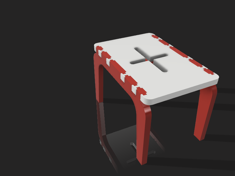
- The Plan: Bench w/ 3D joints
- The Method: Parametric Modeling, Assembly Testing, Animation, Rendering…Fusion 360
- The Execution:
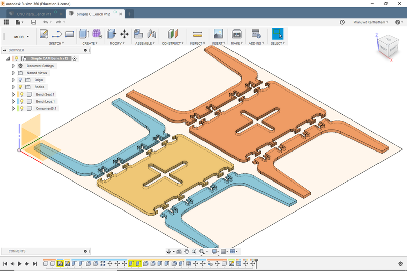
- Design V1.0…”Matrix Bench”, many joints in a complex design
- Group Assignment Test Joint milling…disappointing results, longer than expected cut time
- Time limited…needed to get realistic and redesign…
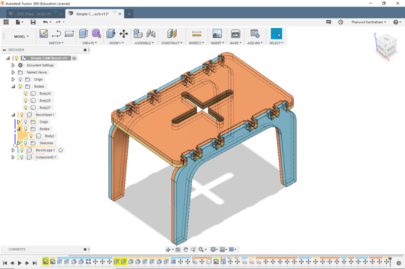
- Design V2.0…simplified bench, reduced number of joints, simple shape
- Render and animate bench model in F360…virtual check for form and fitment
- Satisfied…exported STL file for 3D tool path generation on Vcarve and milling by Shopbot
- 1st Cut…major fail, emergency stop required…incorrect material Z-Origin
- 2nd Cut…trouble free, but lots of Post Production will need to be done (rough edges and details)
- …still in PP
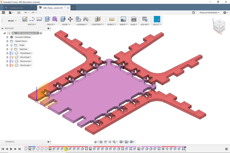
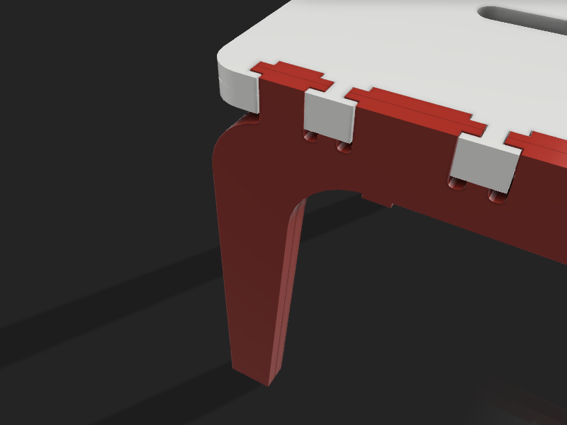
The Hammer Joint
Focused on finding a joint example to recreate, I found this example on Pinterest that I liked…
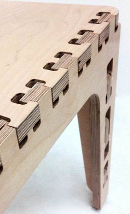
I modeled something similar to be used in my project…

Parametric Modelling
After understanding the power of Parametric Modeling while modeling the Press-Fit Kit using FreeCAD in a previous assignment, I decided to explore a capabilities of this feature on Fusion 360. Naturally, I went to YouTube for help. The video that gave me the basics is here and here.
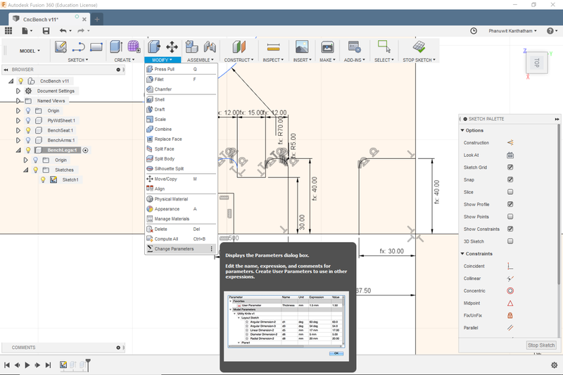
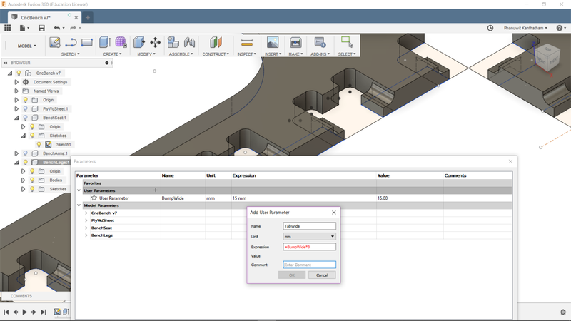
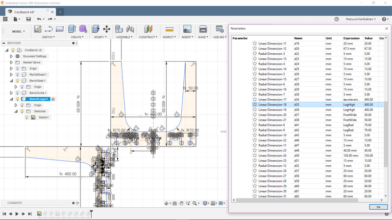
Armed with new knowledge, I aimed to make every single dimension of my bench design be parametric…make it possible that if I wanted to make changes to any dimension in the bench, other dimensions would automatically adjust relationally to that change. The actual setting up of parameters and applying to the model in Fusion 360 became second nature quickly.
Learning Outcome: The difficulty with Parametric Modeling, I learned…was planning the key ‘source’ dimension upon which other ‘dependent’ dimensions would rely on. To describe it in mathematical terms, if the ‘source’ dimension is ‘X’…then all other dimensions should be a function of ‘X’…2X, X + (0.5 * X), etc. Planning an intelligent Parametric structure…takes some thinking.*
“fx” indicates the dimension is parametrically defined…
Test Joint Milling Let me just get it out of the way…I found the Shopbot process not particularly intuitive or easy (especially when the instructions and menu items are in a foreign language). The interface and the procedure feels very much like serious engineering…and not so conducive to experimentation or creativity. Step out of line…and lose a finger, or worse. I can see how running the Shopbot could eventually become less mentally taxing (like learning to ride a motorcycle)…but there MUST be a better way to make CAM on the Shopbot less intimidating and more supportive of creativity.
I used the Shopbot to make a test joint (group assignment) and cut pieces for a bench with 3D joints.
Learning Outcome: The Shopbot is a serious piece of machinery, capable of great feats but also potentially very dangerous…treat it as you would any serious machine, like a car, and operate it accordingly. This is NOT a push a button and relax machine. Be methodical in the operational workflow. Be observant during the milling…and ready to hit the emergency stop button if necessary. Also take safety seriously…with the Shopbot: no loose clothing, wear eye protection…also wear a face mask (to avoid breathing mill dust), and ear protection (milling can be painfully loud). I wear gloves when handling material…but whether one should wear it while the Shopbot is milling is arguable.
Rapid Redesign - Simplification of the Model
Reconciling ambition with temporal reality…there just wasn’t enough time. Simplified the bench to have fewer time-consuming milled joints and multiple connection types. Completed a virtual test fit of the joints to identify any issues…none discovered. Render and animate the model…to improve my F360 competence.
Learning Outcome: The Shopbot needs to be tuned to produce desired results cutting the material you choose It also takes more time than you think to produce reasonable results. Shopbot milling is a time commitment and rushing thru the process will surely produce a bad outcome. Endmill selection, speed & feed settings, making sure the multitude of setting options are correctly selected…will require attention an time.
Shopbot Milling
First attempt…
Vcarve Cut Path File Procedure
This setup procedure was informed by the group work completed. Since we are using the same material to make our project from, the settings and procedures are generally the same.
Define Material Parameters

-
Single Plane
-
Material Size: 1210mm W x 1220mm L x 15mm H
-
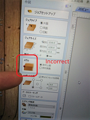
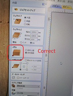
Zero Z-Axis Point: Defined at the bottom lower left corner of the material
-
Zero XY-Axis Point: Defined at the lower left corner of the material
Define Parameters for Specific Types of Milling
For my project, because of the complicated Hammerhead joints…the required milling path needing to be generated were ‘2D’ as well as ‘3D’.
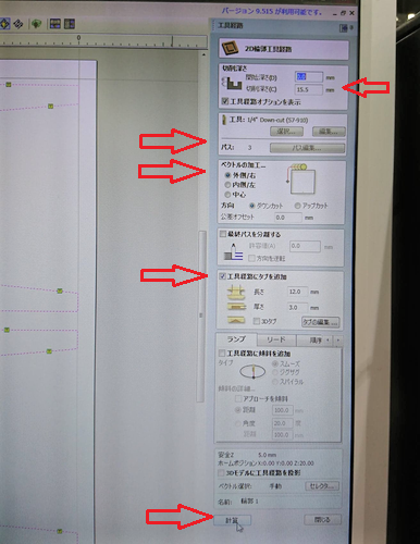
Specify Endmill type and Feed & Speed The endmill used was 1/4” Down-Cutpath.
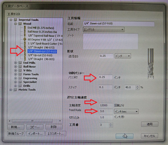
- Speed: RPM set at 12,000
- Feed: Feed Rate set at 3.0 inches/sec
‘Tabs’ also added as a safety precaution…to make sure component pieces cut do not detach and become dangerous projectiles.

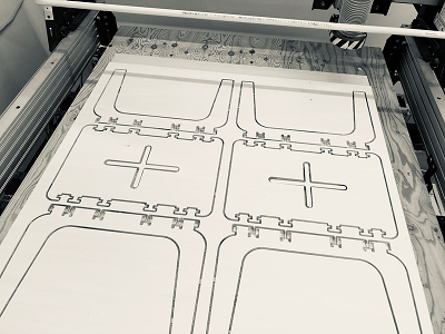
Generate the cut path inspect the generated 3D cut path image when completed…run the preview and look to see any if any cut issues would arise
Shopbot milling
Ran Airpass as a final pre-milling check.
- Set Z-zero to 50mm above the material surface temporarily.
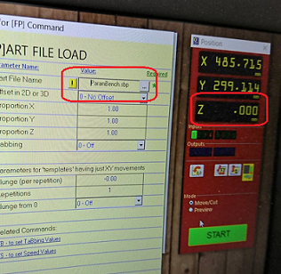
Observed the milling head movements…nothing appeared out of the ordinary. Will learn later that what I needed to observe was both the movement of the milling head AND the changing XYZ numbers on the screen.
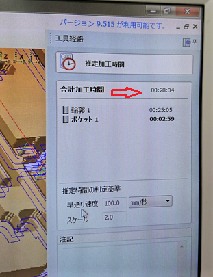
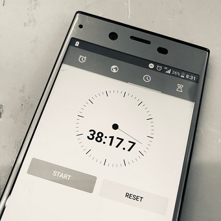
Ready for the cut. Estimated milling time…28mins 4secs
Shopbot Safety Minimum Safety Preparation: Eye protection, no loose clothing. I also recommend an apron (to keep dust off your clothes), face mask (to reduced the amount of mill dust breathed into the lungs, and ear protection (the Shopbot can be painfully loud)
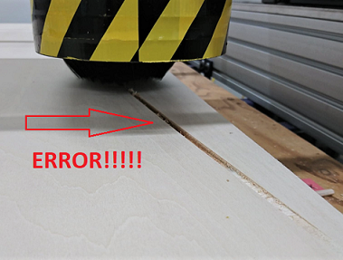
Near disaster!… After finishing the Air Pass, I started the actually milling of the pieces out of the material. A few seconds after start, ss the endmill headed towards the first cut…the bit carved an unexpected, progressively deeper groove into the plywood. Emergency Stop!!!
After much investigation, it was discovered that I made a mistake in defining the Z-origin point of the material…upper corner = wrong…lower corner = correct. Huge thanks to Caterpillar-sensei for his supervision and ninja-like reflexes to leap at the stop button and stop the Shopbot before things became potentially disasterous.
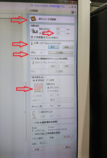
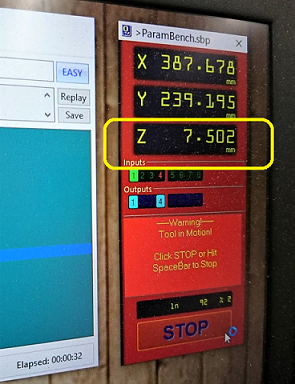
After making the correction, I ran Air Pass again and this time, carefully observed the XYZ location indicator in the PC interface. This time, the lowest the endmill bit tip drops to (for interior cuts) is exactly as expected…@ 7.5mm above the sacrificial layer.
Second Attempt…(fingers crossed)
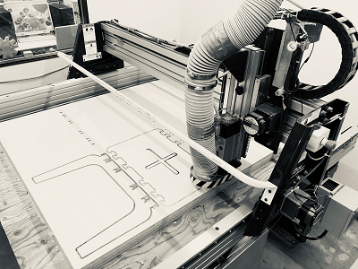
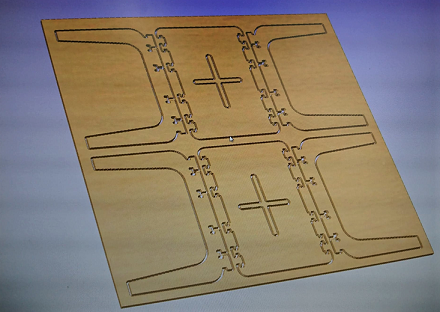
The milling goes well, only a small tab failure at an interior part. Made note to be more mindful about the number and location of tabs when generating cut paths.
10 mins longer than Vcarve estimate of 28 mins. I wonder what the caused the big difference?
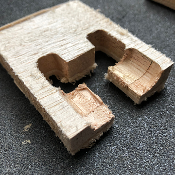
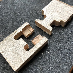
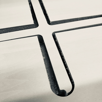
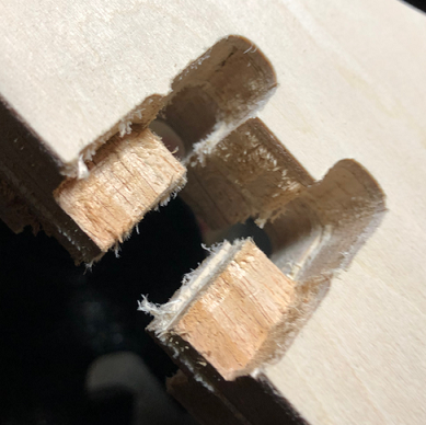
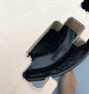
Shopbot had a tough time with small detailed milling, utilizing a 1/4” downcut, twin flute, endmill on the destruction prone Lumber Core Plywood.
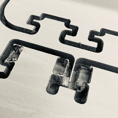
Learning Outcome: The 1/4” downcut endmill was not the appropriate bit for the small detailed work of my model. The Shopbot interface is not the easiest to begin with, harder when it is in an unfamiliar language…good thing an English user manual is available for upload. The milling process takes a long time and unlike 3D printing, the machine cannot be left unattended or unobserved…so multi-tasking during the cut time is really not possible. Feed & Speed tuning really needs to be done to get the best results from a particular material used. A Shopbot session needed just to test speed & feeds.
Lots of left over artifacts…means lots of “Post Processing” work ahead…
Final Assembly - Hero Shots
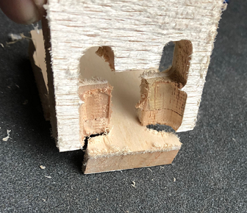
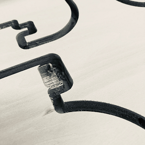
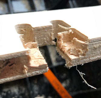
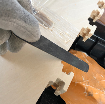
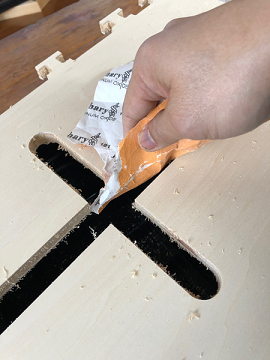
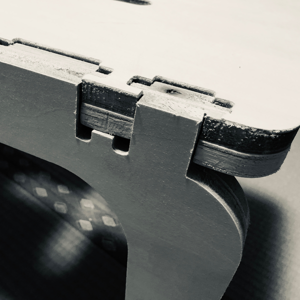
The imprecision observed in the cutting process (due to the material property, I think) did make for some post-processing work…mostly filing down the notch for the Hammerhead joints. After a little work (and a little bit of force) the 4 leg pieces and 2 top surface pieces locked together nicely.
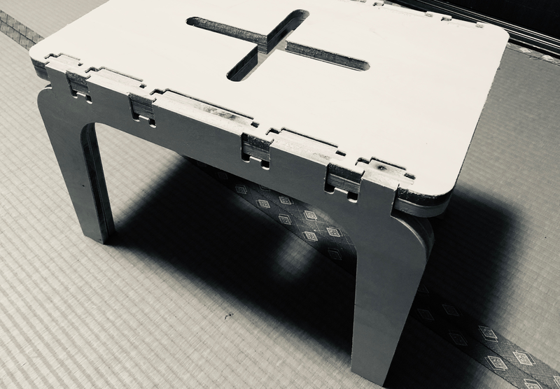
As observed by this image, the fit wasn’t perfect. The surfaces don’t fit perfectly flush. But structurally, the Hammerhead joint is solid and strong.
Procedures
Vcarve procedure
- Define material size…L, D, H
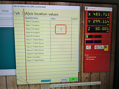
- Define zero point for X,Y, and Z on the 2D and 3D images in the dialogue box…do this mindfully as it can lead to very unexpected movements of the mill head.
- Define exterior milling, interior milling or 3D milling…each of which has its own sub-menus and settings options…cut depth, offset, number of passes.
- Specify endmill type…observe RPM, feed rate and make certain it is appropriate to the material being cut
- Add ‘tabs’ to make sure component pieces cut do not detach and become dangerous projectiles.
- Generate the cut path, inspect the generated 3D cut path image when completed…run the preview and look to see any if any cut issues would arise
Shopbot Procedures
- Zero X and Y…by clicking the auto-zero button on the onscreen interface.
- Zero Z…involves a conductive metal plate (placed flat on the sacrificial layer surface), a clip (attached to spindle to allow for electrical continutiy test)…helpful to have a friend to assist in this proces…once done, raise the Z to get the endmill bit well clear of the sacrificial surface and make the next step (placing project material) easier.
Note: when a friend is anywhere near the milling head of the Shopbot, do NOT have the movement control panel of the Shopbot open…that would allow for movement of the mechanism and injury to said friend
Fix Material to Sacrificial Layer
- Set down material and fix it down to the sacrificial surface…see that the material is not meaningfully warped and not laying flat…fix it in enough locations (in locations not in the cut pieces or anywhere where near where a cut path will be)
Run Airpass
- Run Air Pass…in drill head movement control, move Z to an easy to remember whole number (i.e. 100), after the drill head moves to new Z-location…close movement control panel, at current position indicator…double click Z-number…a spreadsheet should open, change z to zero (effectively telling the shopbot that the current position is the new Z zero position), no need to turn the spindle on, watch milling head movement…also software interface for Z location. After a few minutes (don’t need to watch the whole path) can stop the airpass
- Double click current Z location indicator to bring up the spreadsheet…change Z back to the pre-change location (100 in this example)…preparing the mill head for the actual cutting
Cutting the Material with Vcarve Cutpath
- Turn on dust vacuum
- Turn key to allow spindle movements
- Press start in software interface
- Press Start button on hand control
- …the Shopbot should start cutting the material after a warning sound blares
- Observe the cutting process from start to finish…be ready to press the red emergency stop button if any cutting issues observed
Shopbot Learning outcomes
- Wear gloves to handle large material…apron unless you want dust covering your clothes (lots of dust gets generated)…face mask and goggles
- …and earplugs (for ear protection)…the dust vacuum in a small closed room is…very loud.
- The 1/4” Downcut Endmill has practical limitations as to the fineness and complexity it can cut. Seems best to cut rough outlines but not great for interior assembly details…e.g. complex joints
- Feed and Speed really should be tuned to the material it is cutting…time and effort needs to be allocated to the tuning process and tabular data should be kept at each lab for the materials available for projects locally
- The downcut endmill leaves a really messy bottom edge…is it possible to switch out the milling bit during the cut (pause and restart)? Or does the project need to be cut using two files (main and finish)?…to reduce the amount of post processing work
- Must use tabs to prevent cut pieces from moving while cutting other pieces…Auto-tab OK, but best to review and move tabs as necessary to locations that are sensible in the design and will not be problematic in PP
- Must observe the milling from start to finish, be prepared to stop the mill if something goes wrong. This can take quite some time…don’t be distracted.
Files
Parametric Bench Fusion360 file here
Parametric Bench 2D Vector Data here