2. Final Project - Design Development & Planning
The GYRO9 Wings device is meant to be of relatively compact size, contain all of the required electronics in a clean and attractive package.
Components
- A Microcontroller Unit (MCU)…Satshakit-based Arduino Uno clone, with added headers for ISP programming, sensor board connections
- A 2000mAh battery…allow for minimum of 3hrs of Control Unit and Wing Actuator function while motorcycle riding
- Plug-in Sensors Modules…Phototransistor…(with possible future addition of Accelerometer, Gyroscope, PTemperature, Humidity, etc.)
- Neopixel RGB LED Illumination Arrays…in 3x functional cells (central and 2x wings)
- 2x Servo motors…to actuate the wings
- A Lightweight Waterproof Housing…ideally made of durable ABS plastic), to contain and weather protect the various interior electronic components to IP67 rating
- A Wearable Harness…can be attached and detached from the device
Primary Functionality: Supplementary Rear-Facing Safety Illumination
Auto-On/Off of device…triggered by photo sensor.
- Hands-free ON/OFF of the device’s illumination and wing deployment functions depending on ambient light conditions
- A low light threshold level to be defined in the program to trigger the device ON state when dark enough and OFF when bright enough
- the “ON” event will be confirmed with a 2 second cycling of every LED in the device to confirm functionality…then followed by a steady-state “ON Illumination Subroutine” (OIS) consisting of RED LED illumination at a moderate brightness (in-line with steady state brake light levels of the motorcycle).
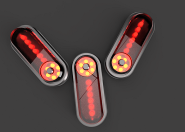
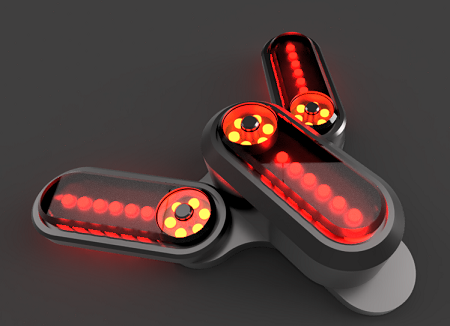
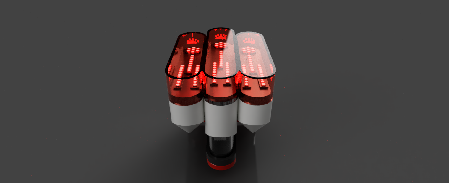
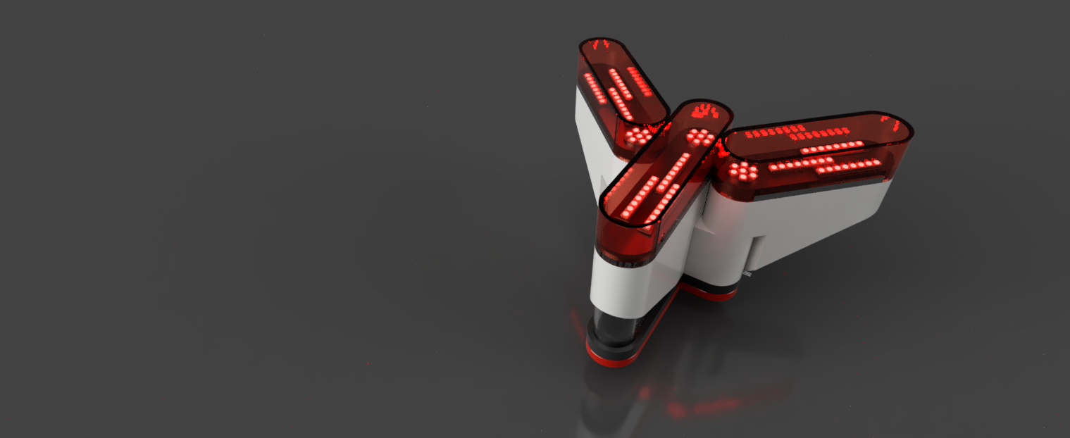
- The “ON” state will also trigger the deployment of the device “Wings” from zero to a 135 degree full-deployment position…the 3 light cells taking a “Y-shaped” configuration.
2D and 3D Modeling
Concept Sketches
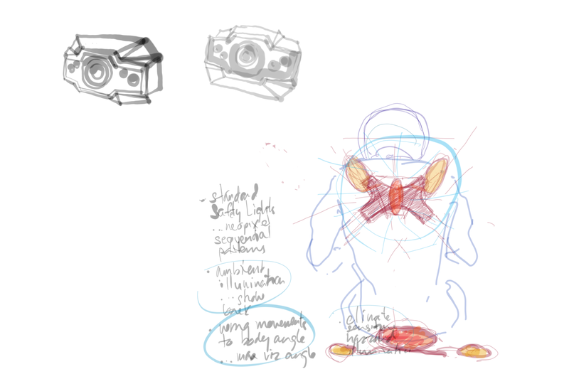
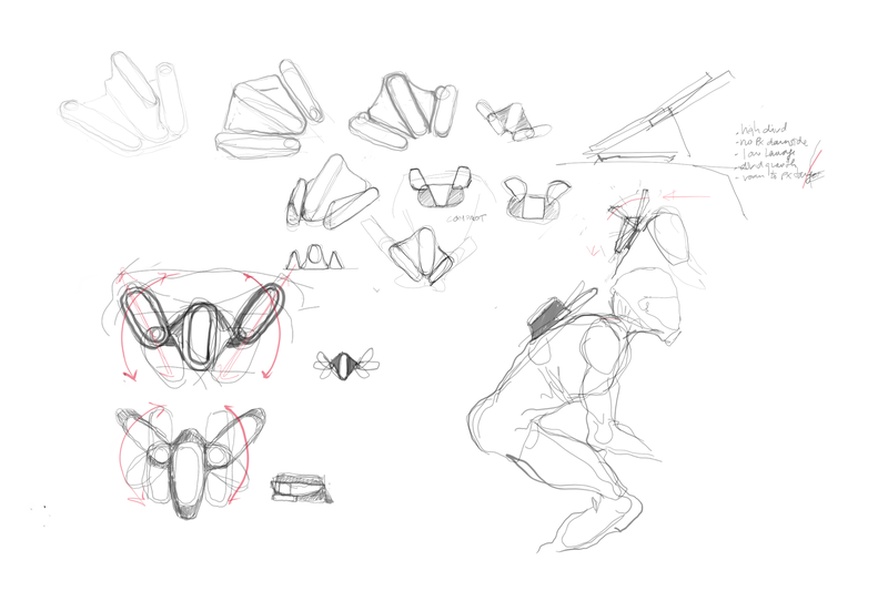
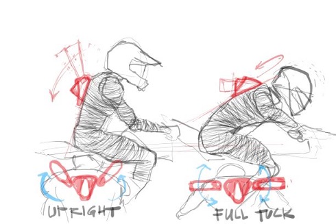

Autodesk Sketchbook
The series of sketches chronologically documents my early thought process in considering the form and function of the GY-RO9 Wings device. Based on these drawings, I settled on a size and form of the device.
First 3D Model Prototype
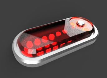
 Autodesk Fusion 360
Using Fusion360, a 3D model of the form factor was developed early on in the process which I liked. The features of the housing are…
- A main central housing to contain the majority of the electronics and battery…and two illuminated “Wings” that will be actuatable
- The light cells will combine a linear light array and a circular one.
No effort was made in this early model to determine whether actual component sizes would fit inside…the primary intent was to get an aesthetic form that would inspire and inform the rest of my work.
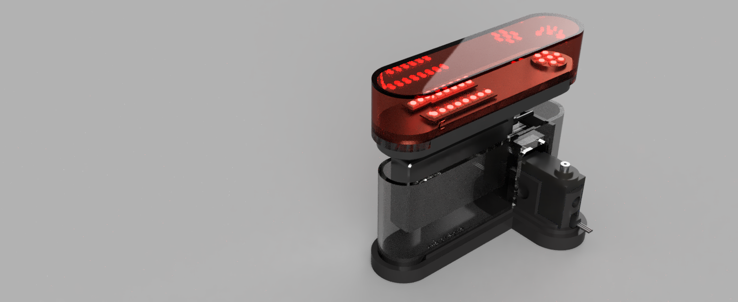
Final Device Design
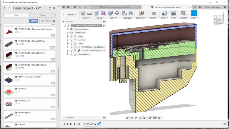
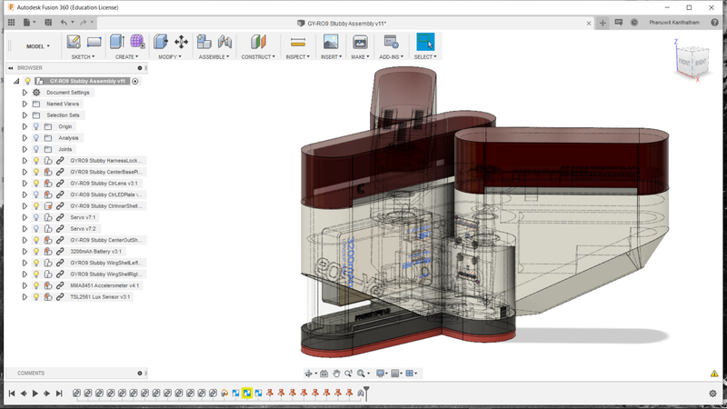
With 2 weeks to the final presentation, final modeling of my device began in earnest. The final device shape and dimensions would be critical in the size and locations of the electronics that it will contain. In Fusion360, I modeled up every component that the device will have to contain in real dimensions and simultaneously worked on the final “shell” form for the device itself.
With a reasonable shape to contain everything generally achieved and mechanical components drafted…

Additive Processes
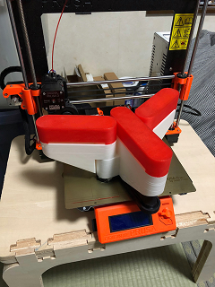
I 3D printed the first prototype of the final project (using PLA) via F360 generated STL files and gcode generated by Prusa Slicer for my Prusa MK3 i3 3D printer.
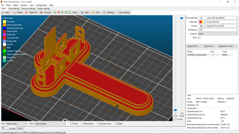
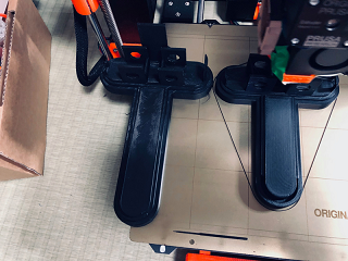
Prints adjustments were made to change sizes and component features, until a final set of 11 distinct prototype parts were printed.
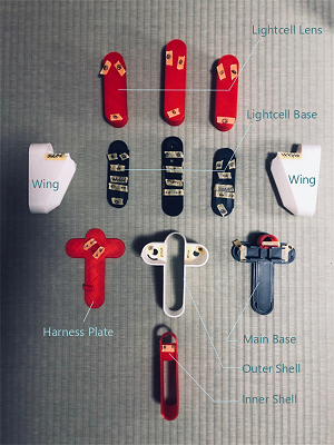
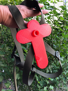
…including a harness plate that can connect to the device itself, so it can be worn on the rider’s back.

Subtractive Processes
Using techniques learned in Molding & Casting week, I created a mold (modeled in Fusion 360, and wax block milled on the Roland SRM20 utilizing an STL file converted to RML file in the Modela software) to resin cast clear, Light defracting lens for my device. Using a resin designed to make water for architectural dioramas (my first time to use this resin) to cast the mold.
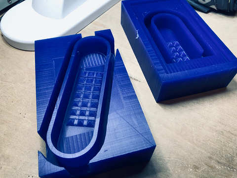
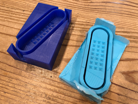
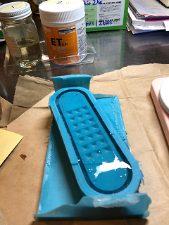
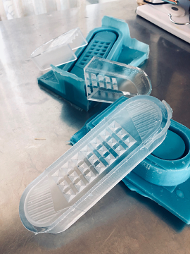
The results are fantastic!…but the curing time is rather long…taking nearly 24hrs to harden enough for use. Temporarily, I will laser cut acrylic light cell cover plates to protect the Neopixels. I will continue to cast protective lenses slowly until they are all done. 4 total casts will eventually need to be made.
Files
Fusion 360 Files:
GYRO9 Fusion360 Model here
STL Models:
Base Plate here
Outer Shell here
Left Wing here
Right Wing here
Wing Spindle here
Center LED Plate here
Center Lens here
Wing LED Plate here
Wing Lens here
Harness Plate here
STL Files - Mold & Cast
Center Lens Mold here
Wing Lens Mold here