4. Final Project - Programming
Time to face the Jabberwocky. Throughout the FabAcademy journey, I had picked up some new skills and became better at others I already knew. Programming, is my Achilles heel (well…Electronics is no easy task either). In the frantic pace of course, I did not spend nearly enough time coding…but now there is no avoiding it. I has reached the climatic end to my ‘Wonderland’ story, the monster is in front me…and I have to somehow cut it down to size…with the wooden sword that I have.
IDE
I had dabbled with various IDEs in a previous weekly assignment. Already with some familiarity with Arduino IDE, I intend to use it for prototyping my final device…taking example sketches relevant to the functions of my project and figuring out a way to “kitbash” together something that resembles a complete program.
During the process, I rediscovered PlatformIO…and after a few minutes of use…understood why former Arduino IDE users rave about it. The added coding assistance features really makes a difference (command completion, pre-compile coding error detection, etc.). I will likely switch over to PlatformIO to do my final coding work…of Arduino sketches.
Programming Language
While I have programmed before (Basic and Pascal) and understood the basic structure of programs, I am unfamiliar with the syntax of modern computer languages. Throughout this course, I have tried to study programming when I can…especially C (particularly Elliot William’s book “AVR Programming”), which Neil recommends as an efficient program for microcontrollers. Unfortunately, I was never able to put the required time into this study to give me adequate proficiency. For my final project, I decided to do my programming work in the Arduino environment.
Activating the MCU as an Arduino UNO
Before getting to functional programming for my device, I needed to make certain that the MCU board I made is functional…can be utilized as an Arduino clone. Using an Arduino Uno as a programmer and utilizing the ISP pins I added (and a set of self-made ISP connector wires!)
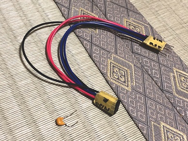
…I uploaded the Arduino bootloader on my MCU.
The Bootload Procedure
- Connect the Arduino Uno to the PC via a USB cable
- Upload the ‘ArduinoISP’ sketch (number 11 in the Arduino IDE’s Example sketch list) onto the Uno…turning it into a ISP programmer
- Connect my MCU board to the Uno using an ISP cable…important!!! A 10uF(?) Capacitor must be inserted into the Uno, bridging the GND and Reset pins…to make ISP programming possible
- In Arduino IDE’s ‘Tools’ menu choose ‘Arduino Genuino/Uno’ as the ‘Board’, ‘Arduino as ISP’ as the ‘Programmer’ (be careful here…there are other similar option ‘ArduinoISP’ and ‘ArduinoISP.org’ which are not correct choices) then select ‘Burn Bootloader’ (at the bottom)…this essentially turns the MCU board into an that the ISP connection is incorrect. Check that MOSI, MISO, SCK, RESET, VCC and GND pins are correctly connected. (In my case, I discovered that neither my Reset nor GND pins were corrected connected in my board design…requiring a fix by soldering bridging wire).

- With the ‘Bootloader’ uploaded to the MCU, any Arduino sketch can be uploaded to the MCU. Open the sketch you want to upload to the MCU…then in the ‘Sketch’ menu, choose ‘Upload Using Programmer’ or use the key combo Ctrl+Shift+U to upload the sketch to the MCU (the right arrow button typically used to upload sketches will NOT work).
- Unplug the USB cable from the PC, the ISP cables between the Arduino and MCU…and now the MCU can be used to drive Input/Output devices using Arduino sketches
Required Libraries
- Serial Communication -
- Allows for monitoring of sensor readings to program debugging work
- Discovered that this library is not suported for the ATTiny chipset…the alternative ‘
‘ library must be used - Adafruit_Neopixel -
- Support for functional use of WS2812 Neopixel addressable RGB LEDs
- Servo -
- Support for actuation of servos
- Note: I discovered that this library is NOT supported by ATTiny processors…the alternative SoftwareServo library (with some adjustment to the .ccp file) needed to be use during prototyping
Component Subroutines
Primary Function (First Spiral): ON/OFF
- Device ON state triggered by ambient luminosity readings by a Photo Transistor rising (as it gets darker) above a threshold level
- ‘ON State’ defined as…
- RED Neopixel LED illumination in a state-state ON condition
- Servo driven ‘Wings’ actuated from zero to 135 degree angle relative to the central housing
- Device OFF state triggered by ambient luminosity sensor readings dropping a threshold level
- ‘OFF State’ defined as…
- LED illumination fully OFF…drawing minimum current
- ‘Wings’ returns to zero angle relative to the central housing (parallel)
Steady State Neopixel ON Illumination and Wing Deployment
Input: Photo Transister Output: Neopixel RGB LEDs, Servos
Program Function Objective:
- The Phototransistor measures ambient light levels…generates analog INPUT signals
- When the level of ambient light level drops low enough (the sensor levels rises high enough), where visibility of the motorcyclist starts to become difficult…the phototransistor signal triggers
- The “ON Illumination Subroutine” (OIS)
- Initiates with a cycling of RGBs, confirming functionality…approximately 2 seconds
- Then settles into a constant RED LED illumination of a brightness consistent with the motorcycle rear brake light…i.e. the GYRO-9 Wings serves as a supplementary, eye-level, rear safety light
- The deployment of the Wings to ‘Open’ positions
- The wings rotate to a full deployment position of 135 degrees (and -135 degrees) relative to the central housing.
- When the level of ambient light rises high enough (and the senor values drops below a threshold), where visibility of the motorcyclist is adequate, the photo transistor signal triggers the “Sleep Mode”
- All illumination programs shutdown and the wings return to 0 degrees relative to the housing, leaving only the ON/OF button glowing…where the GYRO-9 Wings device draws minimal amount of battery power. (will need an On/Off switch!..to fully power ON/OFF the device).
Programming Strategy
Similar to my approach on electronics, because of my shortage of applicable knowledge, I chose to utilize example and other sketches made by professionals and is known to function as the basis of my final program. I chose to approach programming systematically in incremental steps as follows…
- Test MCU communication with the Light sensor…see if the program can see serial data output from the Sensor
- Test MCU communication with servos…see if the program can make servos move to specific rotational positions
- Test MCU communication with neopixels…see if the program can turn ON and Off the neopixels and change colors in the way I hoped
- Test Light sensor activation of servos…see if setting a specific light sensor level can move the servo spindle to a specific rotational position
- Test Light sensor activation of neopixels…see if setting a specific light sensor level can move trigger the running of a specific, dynamic neopixel illumination program
- …then lastly, combine the last two tests into a single program…where a specific light reading from the Light Sensor would trigger the neopixel to turn ON and the servo to move its spindles to a specific rotational position
Programming
A number of programs were used to fulfill the programming strategies I set out. The various testing and final composite programs as follows…
- MCU >> Lux Sensor
// Phanuwit Kanthatham, FabAcademy 2019, FabLab Kamakura
// A simple program to establish and test a connection between
//...the Phototransistor and the MCU


#include <SoftwareSerial.h>

const int LuxPin = A3;  // Sets constant variable for Arduino pin A3
                        // ...as the analog signal pin to Lux sensor

SoftwareSerial LuxSerial(1,2);

void setup() {
  LuxSerial.begin(9600);       // Starts up serial communication
  pinMode(LuxPin,INPUT);       // Sets the A3 pin where the Lux sensor
                               // ...is connected as INPUT

}

void loop() {
  int LuxVal = analogRead(LuxPin); // Reads analog values from PhotoTransistor sensor

  LuxSerial.print(LuxVal);        // Prints PhotoTransistor value in serial monitor
  LuxSerial.print('\n');
  delay(500);           // Wait 500ms before reading from the sensor and printing value again

}
Test Observations - Light Sensor
- The Phototransistor outputs readings in the range of between 0 (completely dark) and 1000 (fully bright).
- Reading frequency can be specified by adjusting the delay between the ‘print(Luxval)’ command I specified.
- I do not need super frequent readings and set the delay to a reasonably rapid 500ms…although as much as 5000ms is probably tolerable
- The level that I believe best represents low visibility ambient light conditions is ~200
-
200 is the threshold level I will set as the trigger for my ON state.
-
MCU >> Servo
// Phanuwit Kanthatham, FabAcademy 2019, FabLab Kamakura
// This program a small modification of...
/* Sweep
 by BARRAGAN <http://barraganstudio.com>
 This example code is in the public domain.
 modified 8 Nov 2013
 by Scott Fitzgerald
 http://www.arduino.cc/en/Tutorial/Sweep
*/
//...to establish and test connection between
//...Servos and the MCU

#include <Servo.h>

Servo myservo;  // create servo object to control a servo
// twelve servo objects can be created on most boards

int pos = 0;    // variable to store the servo position

void setup() {
  myservo.attach(6);  // attaches the servo on pin PA6 to the servo object
}

void loop() {
  for (pos = 0; pos <= 135; pos += 1) { // goes from 0 degrees to 180 degrees
    // in steps of 1 degree
    myservo.write(pos);              // tell servo to go to position in variable 'pos'
    delay(15);                       // waits 15ms for the servo to reach the position
  }
  //for (pos = 135; pos >= 0; pos -= 1) { // goes from 180 degrees to 0 degrees
  //myservo.write(pos);              // tell servo to go to position in variable 'pos'
  //delay(15);                       // waits 15ms for the servo to reach the position
  //}
}
Test Observations - Servo - Servo movements can be very harsh and sudden…and result in a sudden current draw spike - My servos are capable of a movement range between 0 and 180 degrees - I set my fully deployed wing position at 135 degrees
- MCU >> Neopixel
/ A basic everyday NeoPixel strip test program.

// NEOPIXEL BEST PRACTICES for most reliable operation:
// - Add 1000 uF CAPACITOR between NeoPixel strip's + and - connections.
// - MINIMIZE WIRING LENGTH between microcontroller board and first pixel.
// - NeoPixel strip's DATA-IN should pass through a 300-500 OHM RESISTOR.
// - AVOID connecting NeoPixels on a LIVE CIRCUIT. If you must, ALWAYS
//   connect GROUND (-) first, then +, then data.
// - When using a 3.3V microcontroller with a 5V-powered NeoPixel strip,
//   a LOGIC-LEVEL CONVERTER on the data line is STRONGLY RECOMMENDED.
// (Skipping these may work OK on your workbench but can fail in the field)

#include <Adafruit_NeoPixel.h>
#ifdef __AVR__
 #include <avr/power.h> // Required for 16 MHz Adafruit Trinket
#endif

// Which pin on the Arduino is connected to the NeoPixels?
// On a Trinket or Gemma we suggest changing this to 1:
#define LED_PIN    6

// How many NeoPixels are attached to the Arduino?
#define LED_COUNT 8

// Declare our NeoPixel strip object:
Adafruit_NeoPixel strip(LED_COUNT, LED_PIN, NEO_GRB + NEO_KHZ800);
// Argument 1 = Number of pixels in NeoPixel strip
// Argument 2 = Arduino pin number (most are valid)
// Argument 3 = Pixel type flags, add together as needed:
//   NEO_KHZ800  800 KHz bitstream (most NeoPixel products w/WS2812 LEDs)
//   NEO_KHZ400  400 KHz (classic 'v1' (not v2) FLORA pixels, WS2811 drivers)
//   NEO_GRB     Pixels are wired for GRB bitstream (most NeoPixel products)
//   NEO_RGB     Pixels are wired for RGB bitstream (v1 FLORA pixels, not v2)
//   NEO_RGBW    Pixels are wired for RGBW bitstream (NeoPixel RGBW products)


// setup() function -- runs once at startup --------------------------------

void setup() {
  // These lines are specifically to support the Adafruit Trinket 5V 16 MHz.
  // Any other board, you can remove this part (but no harm leaving it):
#if defined(__AVR_ATtiny85__) && (F_CPU == 16000000)
  clock_prescale_set(clock_div_1);
#endif
  // END of Trinket-specific code.

  strip.begin();           // INITIALIZE NeoPixel strip object (REQUIRED)
  strip.show();            // Turn OFF all pixels ASAP
  strip.setBrightness(50); // Set BRIGHTNESS to about 1/5 (max = 255)
}


// loop() function -- runs repeatedly as long as board is on ---------------

void loop() {
  // Fill along the length of the strip in various colors...
  colorWipe(strip.Color(255,   0,   0), 50); // Red
  colorWipe(strip.Color(  0, 255,   0), 50); // Green
  colorWipe(strip.Color(  0,   0, 255), 50); // Blue

  // Do a theater marquee effect in various colors...
  theaterChase(strip.Color(127, 127, 127), 50); // White, half brightness
  theaterChase(strip.Color(127,   0,   0), 50); // Red, half brightness
  theaterChase(strip.Color(  0,   0, 127), 50); // Blue, half brightness

  rainbow(10);             // Flowing rainbow cycle along the whole strip
  theaterChaseRainbow(50); // Rainbow-enhanced theaterChase variant
}


// Some functions of our own for creating animated effects -----------------

// Fill strip pixels one after another with a color. Strip is NOT cleared
// first; anything there will be covered pixel by pixel. Pass in color
// (as a single 'packed' 32-bit value, which you can get by calling
// strip.Color(red, green, blue) as shown in the loop() function above),
// and a delay time (in milliseconds) between pixels.
void colorWipe(uint32_t color, int wait) {
  for(int i=0; i<strip.numPixels(); i++) { // For each pixel in strip...
    strip.setPixelColor(i, color);         //  Set pixel's color (in RAM)
    strip.show();                          //  Update strip to match
    delay(wait);                           //  Pause for a moment
  }
}

// Theater-marquee-style chasing lights. Pass in a color (32-bit value,
// a la strip.Color(r,g,b) as mentioned above), and a delay time (in ms)
// between frames.
void theaterChase(uint32_t color, int wait) {
  for(int a=0; a<10; a++) {  // Repeat 10 times...
    for(int b=0; b<3; b++) { //  'b' counts from 0 to 2...
      strip.clear();         //   Set all pixels in RAM to 0 (off)
      // 'c' counts up from 'b' to end of strip in steps of 3...
      for(int c=b; c<strip.numPixels(); c += 3) {
        strip.setPixelColor(c, color); // Set pixel 'c' to value 'color'
      }
      strip.show(); // Update strip with new contents
      delay(wait);  // Pause for a moment
    }
  }
}

// Rainbow cycle along whole strip. Pass delay time (in ms) between frames.
void rainbow(int wait) {
  // Hue of first pixel runs 5 complete loops through the color wheel.
  // Color wheel has a range of 65536 but it's OK if we roll over, so
  // just count from 0 to 5*65536. Adding 256 to firstPixelHue each time
  // means we'll make 5*65536/256 = 1280 passes through this outer loop:
  for(long firstPixelHue = 0; firstPixelHue < 5*65536; firstPixelHue += 256) {
    for(int i=0; i<strip.numPixels(); i++) { // For each pixel in strip...
      // Offset pixel hue by an amount to make one full revolution of the
      // color wheel (range of 65536) along the length of the strip
      // (strip.numPixels() steps):
      int pixelHue = firstPixelHue + (i * 65536L / strip.numPixels());
      // strip.ColorHSV() can take 1 or 3 arguments: a hue (0 to 65535) or
      // optionally add saturation and value (brightness) (each 0 to 255).
      // Here we're using just the single-argument hue variant. The result
      // is passed through strip.gamma32() to provide 'truer' colors
      // before assigning to each pixel:
      strip.setPixelColor(i, strip.gamma32(strip.ColorHSV(pixelHue)));
    }
    strip.show(); // Update strip with new contents
    delay(wait);  // Pause for a moment
  }
}

// Rainbow-enhanced theater marquee. Pass delay time (in ms) between frames.
void theaterChaseRainbow(int wait) {
  int firstPixelHue = 0;     // First pixel starts at red (hue 0)
  for(int a=0; a<30; a++) {  // Repeat 30 times...
    for(int b=0; b<3; b++) { //  'b' counts from 0 to 2...
      strip.clear();         //   Set all pixels in RAM to 0 (off)
      // 'c' counts up from 'b' to end of strip in increments of 3...
      for(int c=b; c<strip.numPixels(); c += 3) {
        // hue of pixel 'c' is offset by an amount to make one full
        // revolution of the color wheel (range 65536) along the length
        // of the strip (strip.numPixels() steps):
        int      hue   = firstPixelHue + c * 65536L / strip.numPixels();
        uint32_t color = strip.gamma32(strip.ColorHSV(hue)); // hue -> RGB
        strip.setPixelColor(c, color); // Set pixel 'c' to value 'color'
      }
      strip.show();                // Update strip with new contents
      delay(wait);                 // Pause for a moment
      firstPixelHue += 65536 / 90; // One cycle of color wheel over 90 frames
    }
  }
}
Test Observations - Neopixel - While I have a total of 93 individual Neopixels…for the purpose of signal addressing…I need to identify only 69 pixels. My circular Neopixel “Coins” have 7 pixels each…21 in total. Each of my 9 Neopixel “Sticks” have 8 pixels on them which totals 72 pixels. But the way I have the “Sticks” wired together…in 3 arrays, each with one stick leading into not one, but two sticks (in a Y-shaped configuration)…each array can be considered to be a series of 16 pixels, not 24.
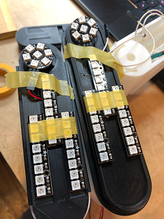
- When powered with a battery with 2A of rated current output, the full set of Neopixels operate without issue. A battery with less than 2A output, however, leads to the Neopixel arrays only partially lighting
-
Properly powered, the 3 Neopixel arrays (each with one “Coin” and 3 “Sticks”) operate beautifully.
-
MCU >> Lux Sensor >> Servo
// Phanuwit Kanthatham, Fab Academy 2019, FabLab Kamakura
// This program to establish and test connection
//...between the MCU >> Light Sensor >> Servos
//...Light Sensor as input trigger to move 2 servos
//...specific, mirror-image rotational position

#include <Servo.h>                //Servo library

Servo servoLeft;                  //Define ServoLeft as servo object
Servo servoRight;                 //Define ServoRight as servo object

const int LuxPin = A3;            // Sets constant variable for Arduino pin A3
                                  // (ATTiny45 pin PB3 in actuality)
                                  // ...as the analog signal pin to Lux sensor
const int SrvoPinL = 5;           // Sets Arduino Pin 4 as LED pin
                                  // (ATTiny45 pin PB4 in actuality)
const int SrvoPinR = 6;           // Sets Arduino Pin 4 as LED pin
                                  // (ATTiny45 pin PB4 in actuality)
int startPosL = 180;                // Variable for start angle for left servo
int startPosR = 180;               // Variable for start angle for right servo
int deployPos = 135;              // Variable for start angle for servo

void setup() {
  Serial.begin(9600);             // Starts up serial communication

// Set up Lux sensor here...
  pinMode(LuxPin,INPUT);          // Sets the A3 pin where the Lux sensor
                                  // ...is connected as INPUT


// Set up Neopixel here...

// Set up Servos here...
  servoLeft.attach(SrvoPinL);     // Attaches servoLeft to digital pin 5
  servoRight.attach(SrvoPinR);    // Attaches servoRight to digital pin 6

  servoLeft.write(startPosL);      // Sets servo start position
  servoRight.write(startPosR);     // Set servo start position

  delay(2000);                    // Wait 2s before moving on to loop


}

void loop() {
  int LuxVal = analogRead(LuxPin); // Reads analog values from PhotoTransistor sensor

  Serial.print(LuxVal);        // Prints PhotoTransistor value in serial monitor
  Serial.print('\n');
  delay(500);                     // Wait 500ms before reading from the sensor and printing value again


  if(LuxVal>50){
    servoLeft.write(startPosL);        // Returns left servo spindle to home...zero angle
    servoRight.write(startPosR);       // Returns Right servo spindle to home...zero angle
    delay(15);                        // Wait for servos to reach position

                            // Wait for servos to reach position
  }
  else {
    servoLeft.write(deployPos);       // Rotates servo spindle to full deploy position
    servoRight.write(startPosR-deployPos);     // Rotates servo spindle to full deploy position
    delay(15);
  }
}
Test Observations - Light Sensor + Servo - There is a noticeable delay (approximately 1 second) between the light sensor being darkened and the servos moving into position…but the servos do move as expected…the delay not really an issue operationally.
- MCU >> Lux Sensor >> Neopixel
// Phanuwit Kanthatham, FabAcademy 2019, FabLab Kamakura
// This code based on original by Adafruit, the "Strandtest" example
//...establishes and tests connection between
//...MCU >> Light Sensor >> Neopixel
//...light sensor input triggers Neopixel illumination programs

#include <Adafruit_NeoPixel.h>
#ifdef __AVR__
#include <avr/power.h>         // Required for 16 MHz Adafruit Trinket
#endif

// What Pins used for NeoPixels?

#define NPXLS_PIN    7          //Pin for Neopixel Sticks
#define NPXLC_PIN    8          //Pin for Neopixel Coins

// How many NeoPixels are attached to the Arduino?

#define NPXLS_COUNT 16          //LED count Neopixel Stick
#define NPXLC_COUNT 7           //LED count Neopixel Coin

// Declare our NeoPixel stick object:
Adafruit_NeoPixel stick(NPXLS_COUNT, NPXLS_PIN, NEO_GRB + NEO_KHZ800);  //Neopixel Stick
Adafruit_NeoPixel coin(NPXLC_COUNT, NPXLC_PIN, NEO_GRB + NEO_KHZ800);   //Neopixel Coin

int pauseS = 50;
int pauseF = 30;
int bright = 50;

// Setup Lux Sensor
const int LuxPin = A3;            // Sets constant variable for Arduino pin A3
// ...as the analog signal pin to Lux sensor
int dusk = 200;                   // Set threshold light level to trigger ON


// Neopixel Functions

// ColorWipe Function:
// Fill stick pixels one after another with a color. stick is NOT cleared
// first; anything there will be covered pixel by pixel. Pass in color
// (as a single 'packed' 32-bit value, which you can get by calling
// stick.Color(red, green, blue) as shown in the loop() function above),
// and a delay time (in milliseconds) between pixels.

// ColorWipe for Stick:
void colorWipeS(uint32_t color, int wait) {
  for (int i = 0; i < stick.numPixels(); i++) { // For each pixel in stick...
    stick.setPixelColor(i, color);            //  Set pixel's color (in RAM)
    stick.show();                             //  Update stick to match
    delay(wait);                               //  Pause for a moment
  }
}

// ColorWipe for Coin:
void colorWipeC(uint32_t color, int wait) {
  for (int i = 0; i < coin.numPixels(); i++) { // For each pixel in stick...
    coin.setPixelColor(i, color);             //  Set pixel's color (in RAM)
    coin.show();                              //  Update stick to match
    delay(wait);                              //  Pause for a moment
  }
}

// Theater Marquis Function:
// Theater-marquee-style chasing lights. Pass in a color (32-bit value,
// a la stick.Color(r,g,b) as mentioned above), and a delay time (in ms)
// between frames.

// Theater Marquis for Stick:
void theaterChaseS(uint32_t color, int wait) {
  for (int a = 0; a < 10; a++) { // Repeat 10 times...
    for (int b = 0; b < 3; b++) { //  'b' counts from 0 to 2...
      stick.clear();         //   Set all pixels in RAM to 0 (off)
      // 'c' counts up from 'b' to end of stick in steps of 3...
      for (int c = b; c < stick.numPixels(); c += 3) {
        stick.setPixelColor(c, color); // Set pixel 'c' to value 'color'
      }
      stick.show(); // Update stick with new contents
      delay(wait);  // Pause for a moment
    }
  }
}

// Theater Marquis for Coin:
void theaterChaseC(uint32_t color, int wait) {
  for (int a = 0; a < 10; a++) { // Repeat 10 times...
    for (int b = 0; b < 3; b++) { //  'b' counts from 0 to 2...
      coin.clear();         //   Set all pixels in RAM to 0 (off)
      // 'c' counts up from 'b' to end of stick in steps of 3...
      for (int c = b; c < coin.numPixels(); c += 3) {
        coin.setPixelColor(c, color); // Set pixel 'c' to value 'color'
      }
      coin.show(); // Update stick with new contents
      delay(wait);  // Pause for a moment
    }
  }
}

// setup() function -- runs once at startup --------------------------------

void setup() {
  Serial.begin(9600);             // Starts up serial communication

  // Set up Lux sensor here...
  pinMode(LuxPin, INPUT);         // Sets the A3 pin where the Lux sensor
  // ...is connected as INPUT

  // Set up Neopixels here...
  stick.begin();           // INITIALIZE NeoPixel stick object (REQUIRED)
  stick.show();            // Turn OFF all pixels ASAP
  stick.setBrightness(bright); // Set BRIGHTNESS to about 1/5 (max = 255)


  coin.begin();           // INITIALIZE NeoPixel coin object (REQUIRED)
  coin.show();            // Turn OFF all pixels ASAP
  coin.setBrightness(bright); // Set BRIGHTNESS to about 1/5 (max = 255)

  theaterChaseS(stick.Color(255,   0,   0), pauseF); // Red, half brightness
  theaterChaseC(coin.Color(255,   0,   0), pauseF); // Red, half brightness
  theaterChaseS(stick.Color(0,   255,   0), pauseF); // Green, half brightness
  theaterChaseC(coin.Color(0,   255,   0), pauseF); // Green, half brightness
  theaterChaseS(stick.Color(0,   0,   255), pauseF); // Blue, half brightness
  theaterChaseC(coin.Color(0,   0,   255), pauseF); // Blue, half brightness
  delay(1000);                              // wait 1secs
}

// loop() function -- runs repeatedly as long as board is on

void loop() {
  int LuxVal = analogRead(LuxPin);   // Reads analog values from lux sensor

  Serial.print(LuxVal);
  Serial.print('\n');
  delay(50);

  if (LuxVal > dusk) {

    // Start-up Light Sequence
    // Fill along the length of the stick...

    colorWipeS(stick.Color(0,   0,   0), pauseS); // Black
    colorWipeC(coin.Color(0,   0,   0), pauseS); // Black
  }
  else {

    //      Do a theater marquee effect...
    theaterChaseS(stick.Color(127,   0,   0), pauseF); // Red, half brightness
    theaterChaseC(coin.Color(127,   0,   0), pauseF); // Red, half brightness
//    delay(1000);                              // wait 1secs
  }
}
Test Observations - Light Sensor + Neopixel
- The activation of the Neopixel program to the set ‘dark condition’ light levels went thankfully well…the response is near immediate
-
As the system is set to start in the OFF position, with no lights activated…I added code to generate a light pattern at startup…to give me an indication that the light arrays are ready to function.
-
MCU >> Lux Sensor >> Neopixel & Servo
With each component and component code subroutine debugged to functional state (it took some time and lots frustration for this novice programmer)…it is time to combine everything into one program.
// Phanuwit Kanthatham, FabAcademy 2019, FabLab Kamakura
// Code based on original by Adafruit Strandtest and Sweep sketch by BARRAGAN  <http://barraganstudio.com>
// Integrates all input (light sensor) and output (servo, neopixel) devices with the MCU
// When a low light condition is observed by the light sensor
// ...it triggers the ON state for both the Neopixel and Servos

#include <Servo.h>                //Servo library
#include <Adafruit_NeoPixel.h>
#ifdef __AVR__
#include <avr/power.h>         // Required for 16 MHz Adafruit Trinket
#endif

// Setup Lux Sensor Pin
const int LuxPin = A3;            // Sets constant variable for Arduino pin A3
// ...as the analog signal pin to Lux sensor
int dusk = 150;                   // Set threshold light level to trigger ON

// Set up Servos
Servo servoLeft;                  //Define ServoLeft as servo object
Servo servoRight;                 //Define ServoRight as servo object

const int SrvoPinL = 5;           // Sets PWM D5 as left servo pin
const int SrvoPinR = 6;           // Sets PWM D6 as right servo pin

int startPosL = 0;                // Variable for start angle for left servo
int startPosR = 180;               // Variable for start angle for right servo
int deployPos = 135;              // Variable for start angle for servo
int speed = 200;

// Set up NeoPixel
#define NPXLS_PIN    7          //Pin for Neopixel Sticks
#define NPXLC_PIN    8          //Pin for Neopixel Coins
#define NPXLS_COUNT 16          //LED count Neopixel Stick
#define NPXLC_COUNT 7           //LED count Neopixel Coin

// Declare NeoPixel stick object:
Adafruit_NeoPixel stick(NPXLS_COUNT, NPXLS_PIN, NEO_GRB + NEO_KHZ800);  //Neopixel Stick
Adafruit_NeoPixel coin(NPXLC_COUNT, NPXLC_PIN, NEO_GRB + NEO_KHZ800);   //Neopixel Coin

int pauseS = 50;
int pauseF = 30;
int bright = 50;

// Neopixel Functions in GYRO9 Project

// ColorWipe Function:
// Fill stick pixels one after another with a color. stick is NOT cleared
// first; anything there will be covered pixel by pixel. Pass in color
// (as a single 'packed' 32-bit value, which you can get by calling
// stick.Color(red, green, blue) as shown in the loop() function above),
// and a delay time (in milliseconds) between pixels.

// ColorWipe for Stick:
void colorWipeS(uint32_t color, int wait) {
  for (int i = 0; i < stick.numPixels(); i++) { // For each pixel in stick...
    stick.setPixelColor(i, color);            //  Set pixel's color (in RAM)
    stick.show();                             //  Update stick to match
    delay(wait);                               //  Pause for a moment
  }
}

// ColorWipe for Coin:
void colorWipeC(uint32_t color, int wait) {
  for (int i = 0; i < coin.numPixels(); i++) { // For each pixel in stick...
    coin.setPixelColor(i, color);             //  Set pixel's color (in RAM)
    coin.show();                              //  Update stick to match
    delay(wait);                              //  Pause for a moment
  }
}

// Theater Marquis Function:
// Theater-marquee-style chasing lights. Pass in a color (32-bit value,
// a la stick.Color(r,g,b) as mentioned above), and a delay time (in ms)
// between frames.

// Theater Marquis for Stick:
void theaterChaseS(uint32_t color, int wait) {
  for (int a = 0; a < 10; a++) { // Repeat 10 times...
    for (int b = 0; b < 3; b++) { //  'b' counts from 0 to 2...
      stick.clear();         //   Set all pixels in RAM to 0 (off)
      // 'c' counts up from 'b' to end of stick in steps of 3...
      for (int c = b; c < stick.numPixels(); c += 3) {
        stick.setPixelColor(c, color); // Set pixel 'c' to value 'color'
      }
      stick.show(); // Update stick with new contents
      delay(wait);  // Pause for a moment
    }
  }
}

// Theater Marquis for Coin:
void theaterChaseC(uint32_t color, int wait) {
  for (int a = 0; a < 10; a++) { // Repeat 10 times...
    for (int b = 0; b < 3; b++) { //  'b' counts from 0 to 2...
      coin.clear();         //   Set all pixels in RAM to 0 (off)
      // 'c' counts up from 'b' to end of stick in steps of 3...
      for (int c = b; c < coin.numPixels(); c += 3) {
        coin.setPixelColor(c, color); // Set pixel 'c' to value 'color'
      }
      coin.show(); // Update stick with new contents
      delay(wait);  // Pause for a moment
    }
  }
}

// setup() function...runs once at startup

void setup() {
  Serial.begin(9600);             // Starts up serial communication

  // Set up Lux sensor here...
  pinMode(LuxPin, INPUT);         // Sets the A3 pin where the Lux sensor
                                  // ...is connected as INPUT


  // Set up Servos here...
  servoLeft.attach(SrvoPinL);     // Attaches servoLeft to digital pin 5
  servoRight.attach(SrvoPinR);    // Attaches servoRight to digital pin 9

  servoLeft.write(startPosL);      // Sets servo start position
  servoRight.write(startPosR);     // Set servo start position


  // Set up Neopixels here...
  stick.begin();           // INITIALIZE NeoPixel stick object (REQUIRED)
  stick.show();            // Turn OFF all pixels ASAP
  stick.setBrightness(bright); // Set BRIGHTNESS to about 1/5 (max = 255)


  coin.begin();           // INITIALIZE NeoPixel coin object (REQUIRED)
  coin.show();            // Turn OFF all pixels ASAP
  coin.setBrightness(bright); // Set BRIGHTNESS to about 1/5 (max = 255)

  // Run Neopixel Startup Routine
  colorWipeS(stick.Color(255,   0,   0), pauseS); // Red
  colorWipeC(coin.Color(255,   0,   0), pauseS); // Red

  colorWipeS(stick.Color(  0, 255,   0), pauseS); // Green
  colorWipeC(coin.Color(  0, 255,   0), pauseS); // Green

  colorWipeS(stick.Color(  0,   0, 255), pauseS); // Blue
  colorWipeC(coin.Color(  0,   0, 255), pauseS); // Blue

  delay(1000);                              // wait 1secs
}

// loop() function -- runs repeatedly as long as board is on

void loop() {
  int LuxVal = analogRead(LuxPin);   // Reads analog values from lux sensor

  Serial.print(LuxVal);
  Serial.print('\n');
  delay(50);

  if (LuxVal > dusk) {         // Not Dark...

    // Fill Black along the length of the stick...
    colorWipeS(stick.Color(0,   0,   0), pauseS); // Black
    colorWipeC(coin.Color(0,   0,   0), pauseS); // Black

    // Servo at Start Position when bright
    servoLeft.write(startPosL);        // Returns left servo spindle to home...zero angle
    servoRight.write(startPosR);       // Returns Right servo spindle to home...zero angle
    delay(speed);                        // Wait for servos to reach position


  }
  else { // dark

    //      Do a theater marquee effect in various colors...
    theaterChaseS(stick.Color(127,   0,   0), pauseF); // Red, half brightness
    theaterChaseC(coin.Color(127,   0,   0), pauseF); // Red, half brightness

    // Servo to full Deploy position
    servoLeft.write(deployPos);       // Rotates servo spindle to full deploy position
    servoRight.write(startPosR - deployPos);   // Rotates servo spindle to full deploy position
    delay(speed);

  }
}
Test Observations - Full Program - The aggregation of the program components goes well, the full system behaving in-line with previous sub-component tests. - Unlike when the code was just to drive the Neopixels with the MCU…the functions that generate the different light programs needed to be moved from the end of the program to before the ‘void setup’ section for the program to compile properly
5. Finally…Project Summary >>
Appendix - Future Development Plans & Research
Future Addition - Secondary Function (Second Spiral): Brake Light Flash & Wing Angle Adjustment**
- RED Neopixel LED flashes when sudden deceleration relative to prevailing acceleration (brake force) is detected by the accelerometer…an interrupt occurs
-
Ideally, the stronger the brake force detected…the brighter and faster flashing the RED LEDs…though this may be a third spiral item
-
Brake Light Illumination - BIS
Input: Accelerometer Output: Neopixel RGB LEDs
General Description:
- An Accelerometer measures Acceleration and Deceleration force…generates analog INPUT signals
- When the Accelerometer detects a strong sudden deceleration…it triggers a “Brake Illumination Subroutine” (BIS)
- The “BIS”
- Interrupts the OIS
- Launches an illumination program characterized by flashing of RED LEDs in the Central and Wing housing…the stronger the deceleration, the brighter and faster the RED LEDs flashes (indicating ‘urgency’ to the observer)…the flashing lasts for 2 seconds following the detection of deceleration force
- After flashing…this illumination program goes into a steady-state ON similar to OIS…but at a higher level of Brightness…this illumination is maintained (while the motorcycle is stopping or stopped) until 1 second after an acceleration force is detected (when the motorcycle is no longer braking and accelerating again)
- When acceleration force is detected for longer than 1 second…the BIS program ends and reverts back to OIS
- The BIS will supercede every other subroutine, including HIS (it is the most important)
Testing: - Strandtest example program - theaterMarquis… - initially brightness set at 50, flashing appears fast. - Changed brightness to 150…and flashing rate slows significantly. - Slows again when brightness changed to 250. - Actual brightness difference NOT noticeable…but flash rate clearly changed. - Set brightness to 20 and LEDs flashes with ‘urgency’. - changed delay to 5mS…and added Blue color…result is like police light flashing btwn blue and red
- ‘Wing’ deployment angle adjusts to forward lean angle of rider (minimizing device wind resistance) is detected by accelerometer…an interrupt occurs
-
When a significant change in rider forward lean angle is detected and held for 5 seconds, the ‘Wings’ will move into one of 3 preset angles
- 135 degrees: Rider lean angle between 0 and 15 degrees
- 90 degrees: Rider lean angle between 15 and 30 degrees
-
45 degrees: Rider lean angle >40 degrees
-
Wing Actuation - WAS
Input: Accelerometer Output: Neopixel RGB LEDs
General Description: - (will need 2x servos! but which one?) - The Wings will rotate on its hinge to maintain a position that… - Maximizes light visibility relative to the forward lean angle of the rider - Minimizes wind resistance…take an angle greater than 90 degrees when the rider is upright, take an angle less than 90 degrees when the rider is leaned forward (think the F14 Tomcat’s wing angles…) - After the device is turned on, initiation routine cycles to confirm all components active…and the option for wing actuation is selected by the motorcyclist (another physical button??)…the wings deploy to an “Open” position. - “Open” position - The Wings rotates on its hinges, driven by servo motors, to an angle relative to the central housing between 0 and 135 degrees - The Gyroscope sensor measures the forward lean angle of the motorcyclist…generates analog INPUT signals - Based on the lean angle measured…the wings will take one of 3 preset angled positions… - 135 degrees when the rider is upright, - 90 degrees when the rider is moderately leaned forward - 45 degrees when the rider is in ‘full tuck’ forward lean - When the GYRO-9 Wings enters “Sleep Mode” or “Off Mode”…it will exit the “Open” position and revert to 0 degrees “Close” position relative to the Central Housing (i.e. parallel with)
SoftwareServo Library
During the prototyping phase, I discovered that the typical Arduino Servo Library is not supported for the ATTiny chipset. The alternative is the SoftwareServo Library. A big thank you to FabAcademy 2017 student Jiyoung An for her excellent documentation on this subject here. The Arduino page describing Software Servo Library in detail is here.
8Some key learning outcomes… - Software Servo Library (ssLib) requires “SoftwareServo::refresh()” to be called every ~50ms to keep servos updated - Methods include… - attach(int)…turns pin specified by the integer into a servo driver. Calls pinMode. Returns 0 on failure. - detach()…releases a pin from servo driving. - write(int)…sets the angle of the servo in degrees from 0-180. - read()…returns value of last Write - attached()…returns 1 if servo attached - Servos will not receive control signal…until you send its first position with the write() method…to keep it from jumping to some odd arbitrary value - The library does not stop interrupts…millis() will still work and incoming serial data will not be lost…but a pulse end can be extended by the max length of interrup handles(?) which can cause a small glitch in the servo position. When there are many servos…position distortions (1-3 degrees) will be observed in the ones with low angular value.
Code examples
#include <SoftwareServo.h>  // loads ssLib

SoftwareServo myservo;      // creates servo object here named "myservo"

const int srvoPin = 2       // creates variable "srvoPin" equal integer 2

void setup() {
  myservo.attach(srvoPin);  // calls pinMode on pin 2 as servo driver
  myservo.write(0);         // sets zero as first position of servo
}

void loop() {
  myservo.write(135);       // moves servo position to 135 degrees
  delay(15);                // waits 15ms for the servo to reach position

  SoftwareServo::refresh(); // runs required method to update servo positions

  myservo.write(0);       // moves servo position to 0 degrees
  delay(15);                // waits 15ms for the servo to reach position

  SoftwareServo::refresh(); // runs required method to update servo positions
}
Servo Library & Hardware Timer
(…the following notes based on discussion in Arduino forum here)
- Servo Library uses a hardware timer of the AVR chip
- Hardware timer only issues an interrupt…does not change any output pins
- Inside the interrupt, the function “handle_interrupts” is called…sets the output pins HIGH or LOW for one or more pins.
Millis() Method
(…the following notes based on discussion in Arduino forum here)
The delay() method for timing has limitations…the worst of which is that while it is running…nothing else can run (mostly). The alternative is the millis() method with its non-blocking timing.
Some learning outcome…
- To use…must record the time at which an action took place to start the timing period, then check at frequent intervals whether the required period has elapsed.
- More convenient to read the current value once on each pass of the loop()
currentMillis = millis();
- The variable “currentMillis” must have been previously declared…should be a descriptive name
- Declare 3 global variables before void setup()…
- unsigned long startMillis;
- unsigned long currentMillis;
- const unsigned long period = 1000 // 1000ms or 1sec
- It is an ‘unsigned long’ because that is what millis() returns
- It is important that it is unsigned
Example code ``` unsigned long startMillis; unsigned long currentMillis; const unsigned long period = 10; //10ms or 0.1sec const byte ledPin = 10; //using an LED on a PWM pin byte brightness = 0; //initial brightness byte increment = 1; //amount to change the brightness at the end of each period.
void setup() { Serial.begin(115200); //start Serial in case we need to print debugging info pinMode(ledPin, OUTPUT); //sets pin 10 as OUTPUT pin startMillis = millis(); //initial start time }
void loop() { currentMillis = millis(); //get the current time if (currentMillis - startMillis >= period) //test whether the period has elapsed { analogWrite(ledPin, brightness); //set the brightness of the LED…at zero initially brightness += increment; //will wrap round from 255 to 0 because brightness is an unsigned data type startMillis = currentMillis; //IMPORTANT to save the start time of the current LED brightness } } ``` - If the period has not yet elapsed…other functions can run until the next time elapse check
Example code of two functions occurring simultaneously…not serially
unsigned long blinkStartMillis; //variable for start time of LED blink Subroutine
unsigned long fadeStartMillis; //variable for start time of LED fade subroutine
unsigned long currentMillis;
const unsigned long blinkPeriod = 1000;  //blink period
const unsigned long fadePeriod = 10;  //fade period
const byte blinkLedPin = 13;    //this LED on pin 13 will blink
const byte fadeLedPin = 10;    //this LED on pin 10 will fade
byte brightness = 0;  //initial brightness of LED
byte increment = 1;  //amount to change PWM value at each change

void setup()
{
  Serial.begin(115200);  //start Serial in case we need to print debugging info
  pinMode(blinkLedPin, OUTPUT);
  blinkStartMillis = millis();  //start time of blinking LED
  fadeStartMillis = millis();  //start time of fading LED
}

void loop()
{
  currentMillis = millis();  //get the current time
  blink(); //runs blink Subroutine
  fade();   //rims fade subroutine
}

void blink()  //function to blink an LED if the blink period has ended
{
  if (currentMillis - blinkStartMillis >= blinkPeriod)  //test whether the period has elapsed
  {
    digitalWrite(blinkLedPin, !digitalRead(blinkLedPin));  //if so, change the state of the LED
    blinkStartMillis = currentMillis;  //IMPORTANT to save the start time of the current LED state.
  }
}

void fade()    //function to fade an LED
{
  if (currentMillis - fadeStartMillis >= fadePeriod)  //test whether the period has elapsed
  {
    analogWrite(fadeLedPin, brightness);    //set the brightness of the LED
    brightness += increment;    //will wrap round because brightness is an unsigned data type
    fadeStartMillis = currentMillis;  //IMPORTANT to save the start time of the current LED state.
  }
}
I2C Coding
“How I2C Communication Works and How to Use It In Arduino” by How To Mechatronics video here
- 128 devices on 7bit addressing
- The SDA and SCL lines are ‘Open Drain’ and require ‘Pull-up Resistors’ to give the lines a HIGH state…the devices connected are ‘Active LOW’
- Common ‘Pull-up’ resistors…2K for 400 kbps (fast) speed, or 10k for 100 kbps (lower) speed
- Data signal transferred in sequences of 8 bits…after a special start condition (1 bit)
- Start (1 bit) + Slave Address (8 bits…last bit indicating R/W) + Acknowlege (1 bit) + Slave Internal Register Address (8 bit) + Acknowledge (1 bit) + Data Sequence(s) (8 bit per sequence…until data completely sent) + Acknowlege (1 bit)+ Stop (1 bit)
- i2C Scanner sketch from Arduino official website…useful to see the ‘Device Addresses’ connected to i2C lines
- Internal Register Addresses…look in the ‘Register Map’ of the device’s datasheet
- Arduino ‘Wire Library’ needs to be included in the sketch for i2C to work…then define ‘Device Address’ and ‘Internal Register Addresses’
Example:
#include <Wire.h>

int ADXLAddress = 0x53;

#define X_Axis_Register_DATAX0 0x32
#define X_Axis_Register_DATAX1 0x33
#define Power_Register 0x2D
The Wire Library will be initiated with the Wire.begin() function…and serial communication initiated and baud rate specified if we want to monitor.
void setup() {
  Wire.begin();
  Serial.begin(9600);
}
To get particular data from the sensor (X axis data in this case)…begin transmission, specify particular internal registers, end transmission.
void.loop() {
  Wire.beginTransmission(ADXLAddress);
  Wire.write(X_Axis_Register_DATAX0);
  Wire.write(X_Axis_Register_DATAX1);
  Wire.endTransmission();
}
Then read data from those internal registers with Wire.requestFrom function, specifying the number of Bytes wanted…the Wire.available function will return the number of Bytes available for retrieval…if requested Bytes and available Bytes match…data retrieval occurs
``` Wire.requestFrom(ADXLAddress,2);
if (Wire.available()<=2) { X0 = Wire.read(); X1 = Wire.read(); }
``` The print the data in the serial monitor…
  Serial.print("X0 = ");
  Serial.println(X0);
  Serial.print("      x1 = ");
  Serial.println(X1);
“Connecting Arduino with Multiple i2C devices” by BlueDot video here
Interrupts
An excellent explanation of using interrupts with Arduino here.
Key Learning Outcome:
- Beyond ‘polling’…constant checking a state of a pin (taking way microcontroller processing resources)
- ‘Interrupt’ = section of hardware on microcontroller capable of monitoring the state of an input pin by itself…and can interrupt the micro controller’s in-progress process to let it know there is an interrupt vector ready (the state of the pin has changed)
- ‘Interrupts’ all taken care of by hardware flags and low-level microcontroller instructions…allowing the microcontroller to do other things other than ‘polling’ for states at a pin
- 3 Types of Interrupt Conditions: Change, Rising, Falling
- “Change”: either Rising or Falling signal
- “Rising”: signal going from LOW to HIGH
- “Falling”: signal going from HIGH to LOW
-
“Interrupt Service Routine (ISR)”: when assigned condition triggered, Arduino will run a specific function to that interrupt
-
Some important Do’s and Don’t…Interrupts and Arduino:
- ISR function code should be kept as short as possible!!…the microcontroller will not return to the primary void loop routine until the ISR code is fully executed. Other processes (LCD display or networking) requiring tight timing and integration…will fail if ISR function runs too long. The ISR should be used ONLY to set a flag or change a state…not execute an entire section of code
- Example: a routine runs as normal as long as some variable is equal to 0…but runs a different function if the variable changes to 1…triggered by an ISR
- ISR cannot return Values or take parameters
- Arduino’s ‘Delay’ and ‘Millis’ functions will not work inside ISR (they are interrupt based…and only one interrupt can be occurring at any given time)…however, ‘DelayMicroseconds’ WILL work (not interrupt based)!
- Any (integer) variable changed inside ISR…should be declared with a ‘Volatile’ modifier”
- **Only certain pins have ‘Interrupt’ capabilities…digital pins D2 and D3 on Arduino Uno
-
Not all chips support all 3 kinds of interrupts on all pins
-
‘Interrupts’ signals a state change at a digital pin…from LOW to HIGH, for example…
- Hardware Interrupts…software Interrupts
- Uno’s have 2 interrupt pins…Megas have 6 interrupt pins…
- Nano is a small Uno
- ‘attachInterrupt(pin no, ISR function, trigger mode (rising or falling or change ))’…needed to enable a digital pin for interrupt purpose
- ISR example…
// Lux Sensor ISR
void senseDark() //
  if (LuxSnsr = 1)
  {
    ledOn =
     true;
    digitalWrite (6, HIGH)
  }DelayMicroseconds
  {
    ledOn = false
    digitalWrite (6, LOW)
  }
- interrupt variables MUST be declared ‘Volitile’…be a Bool type when declared as global variables
- ISR tips…keep it short, don’t use delays, don’t do serial prints, make variables shared with the main code Volatile
- Using 2 interrupts: one interrupt when sensor goes from LOW to HIGH…another from when sensor goes from HIGH to LOW…interrupt condition commands go into the void setup section
void setup(){
  pinMode(13,OUTPUT);
  pinMode(2,INPUT);
  pinMode(3,INPUT);
  attachInterrupt(0,turnLEDOn,RISING);
  attachInterrupt(0,turnLEDOff,FALLING);
}
my void loop section should have…
- search for Lux sensor state…if 1 then system ON, if 0 then system remains Off (the default void loop state)
- system ON means…all LEDs runs ‘steadyState’ function and Servos runs ‘fullDeploy’ function (135 deg position)
- system OFF means…all LEDs OFF, and Servos returns to 0 position
for instance…
#include "LowPower.h"

void loop ();
  LowPower.powerDown(Sleep_Forever, ADC_OFF, BOD_OFF);
- Key Arduino Commands Associated with Interrupts
- volatile int
- attachInterrupt(digitalPinToInterrupt(“pin number/name”,”function to run”,”interrupt condition”))