5. Final Project - Assembly
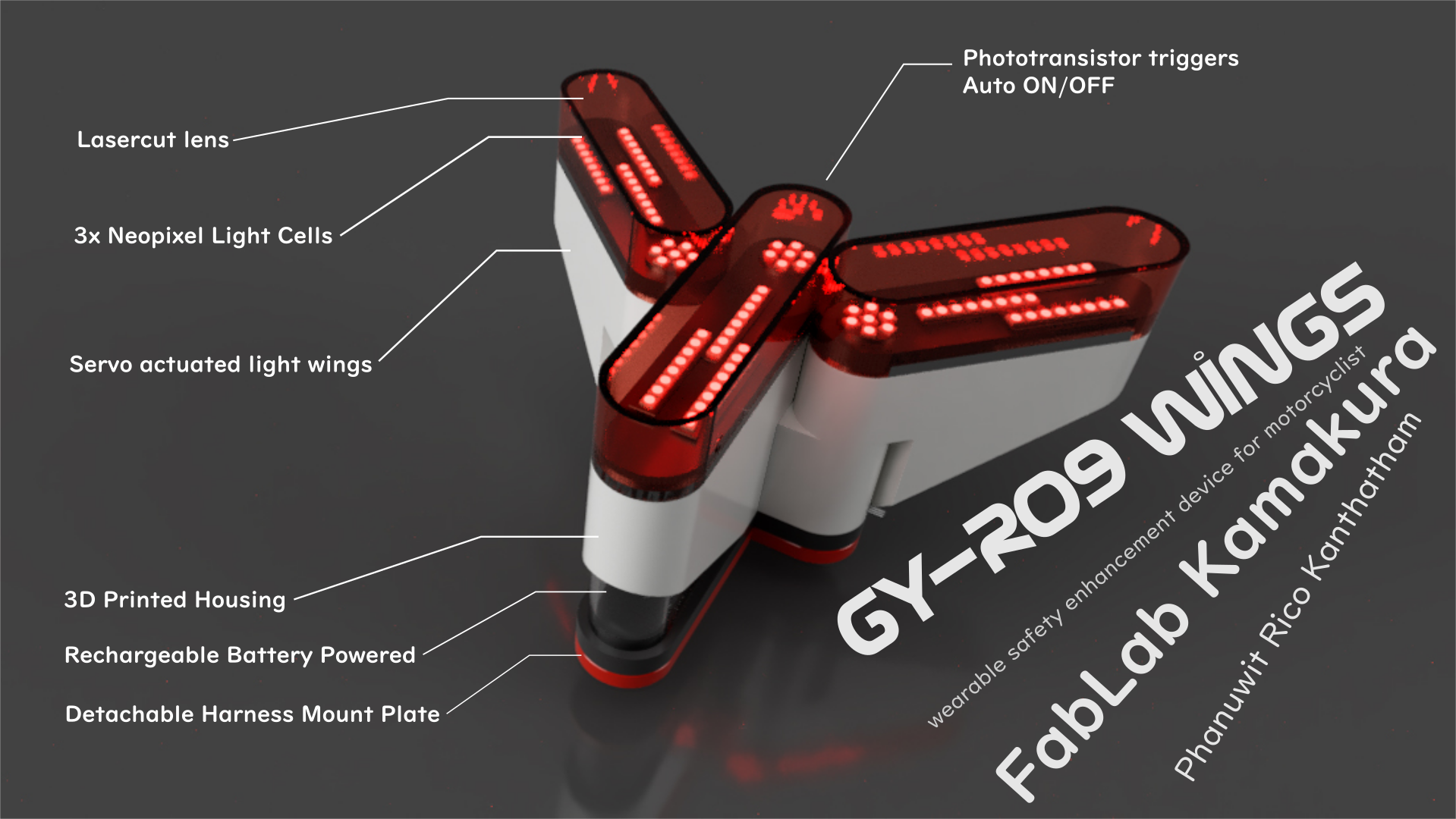
The GY-RO9 Wings
The project video the device is here
The Assembly
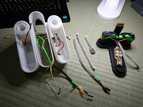
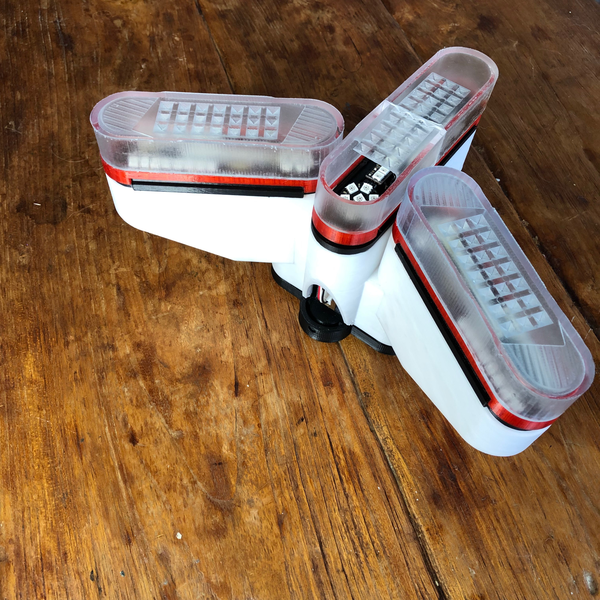
With the physical housing, electronic components and programming completed and tested to reasonable satisfaction, it now came time to assembling everything into an integrated whole. Unfortunately…this proved difficult.
The assembly process came late in the 2 week final project work flow and many…many issues arose.
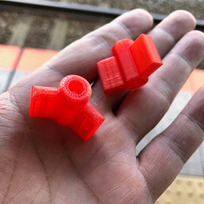
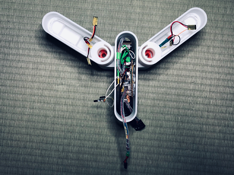
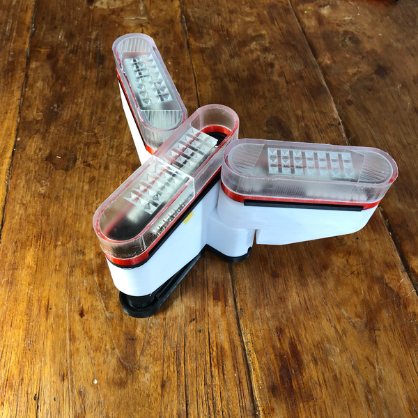
- The mechanical hinge designed to rotate the wings did not interface with the servo well…and wing rotation became less reliable with time, as the screw holding the wing to the servo stopped locking onto the PLA material (slipping from rather than biting into the material).
The Solution: A redesign of the hinge mechanism to introduce an intermediate part that screws firmly onto the servo spindle before attaching to the wing assembly proved to be a winning solution
-
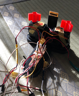
My inexperience with electronics and electrical wiring proved hugely problematic…as lengths and location of wires, and their general disorganization within the limited space inside the housing (the battery and servos and wires filling up the space), resulted in…
-
difficulties making plug connections
- difficulties in maintaining stable connection when the wings were actuated (connections came loose)
- …and worst of all excessive force on pin solder which lead to breakage and operational failure (resoldering or bridging wire required).
The Solution: Lots and lots of debugging time went into figuring out why the system was not behaving as it did successfully …prior to the attempt to enclosing the electronics in the housing. After much frustrating research and adjustments, the solutions resulting in reasonable operations were…
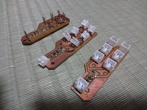
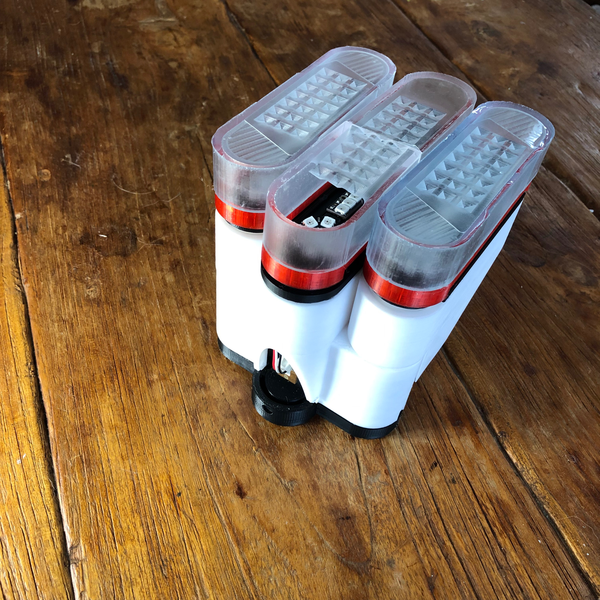
- A new power board with stronger XH connectors. The smaller SP connectors saved space but were too fragile…easily damaged from plugging and unplugging. The oldest version with raw pins were also prone to unplugging.
- Tidying of interior wires. Where possible, I wrapped similar wires (signal wires vs power wires, etc) into bundles…reducing the tangles inside.
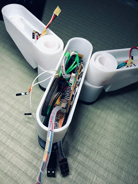
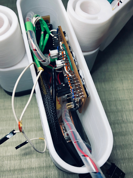
- 2 power sources. The most important adjustment (discovered after much research) was separating the MCU from the current hungry output devices (particularly the current spike causing servos) made for much more reliable operations. At this time, the system is now portable…but power sources have to be outside the housing because the 2 batteries I have are too large for the housing.
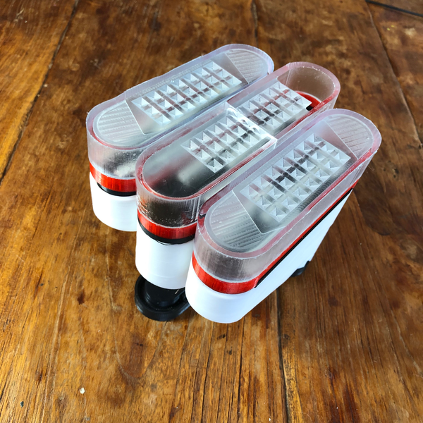
The GY-RO9 Wings - Motorcyle Safety Illumination Device
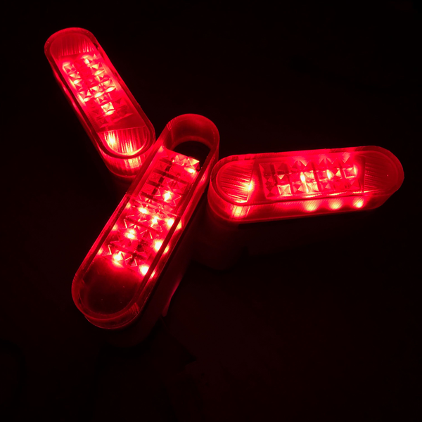
GYRO9 Wings Video
The Next Spiral(s)
After a lot of frustrating debugging, I came away with some important learning outcome…
-
The GYRO9 in its current state is very much a prototype. Reliable, wearable operation on a motorcycle outdoors…will require significant redesign of the housing, electronics, wiring…and coming up with a better power solution.
-
For power…ideally, everything should be powered from a single battery…not two. Small high capacity batteries exist (LiPO) but are exorbitantly expensive and require special chargers (RC charger). I hope to find a solution for a battery that is has adequate capacity (to allow for multiple hours of use), adequate current (for current hungry Neopixels and Servos), be reasonably inexpensive (…less than USD20), and be easy to charge (ideally by plugging in a USB cable). A solution must exist…but will require more research.
-
The current form factor…is still too big in my mind. A smaller form factor to make the device truly portable (but make the task of interior mechanical, electronics and power design that much more difficult).
-
Added functionality to make the device truly intelligent and useful…it is barely scratching the surface now.
-
A waterproofing housing is a must for this device to be realistic as a useful motorcycle accessory.
-
Exterior ON/OFF button to enable/disable battery power
Concluding Thoughts
It’s been a tough but rewarding journey. While I now have a basic foundation of digital fabrication knowledge…‘Mastery’ will require many hundreds of hours of additional work, additional study…and most importantly learning from inevitable failures.
Aside from perfecting the GYRO9 Wings…I already have a list of other projects I would like to begin…including developing methods to teach some of these skills to kids (there were many great examples presented by other students to build from!) and building on the FabCity’s self-sustainability through fabrication concept.
A big thank you to…
-
My instructors and lab leaders at FabLab Kamakura
-
My inspiring classmates
-
My patient family
-
My FabAsia Network classmates
-
…and last but not least Neil Gershenfeld and the FabAcademy for providing an excellent platform for learning that challenged me to be better than I was.
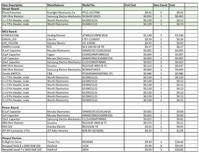
The BOM
Files
Fusion360: GYRO9 model here
Eagle: GYRO9 MCU Board schematic file here
GYRO9 MCU Board routing file here
GYRO9 Sensor Board schematic file here
GYRO9 Sensor Board routing file here
GYRO9 Power Board schematic file here
GYRO9 Power Board routing file here
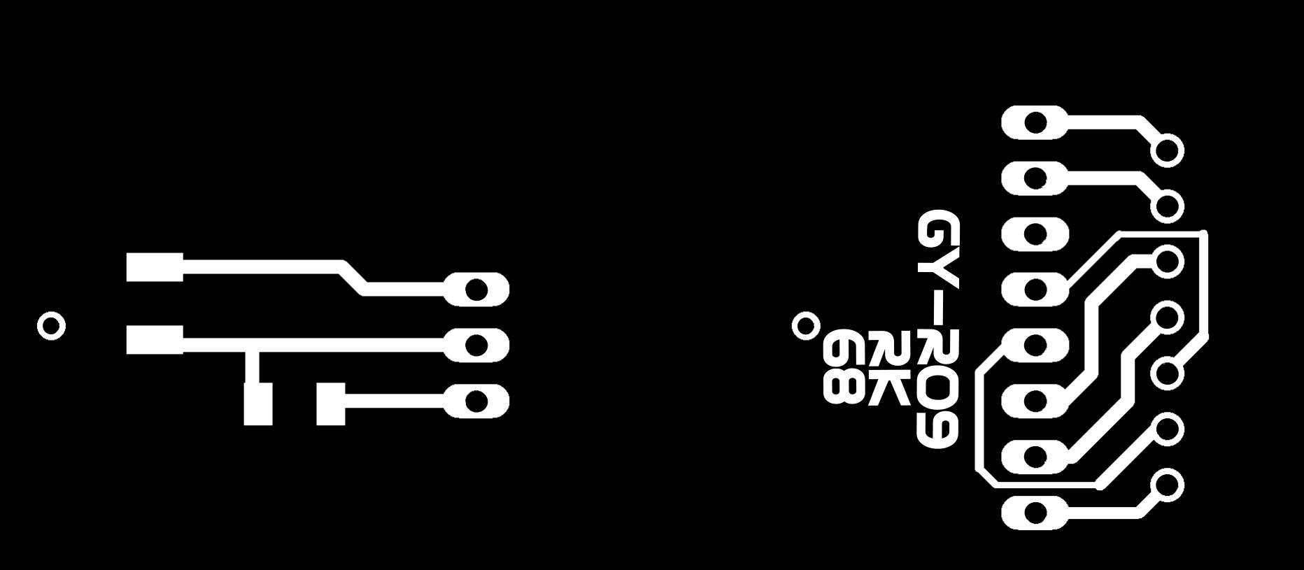
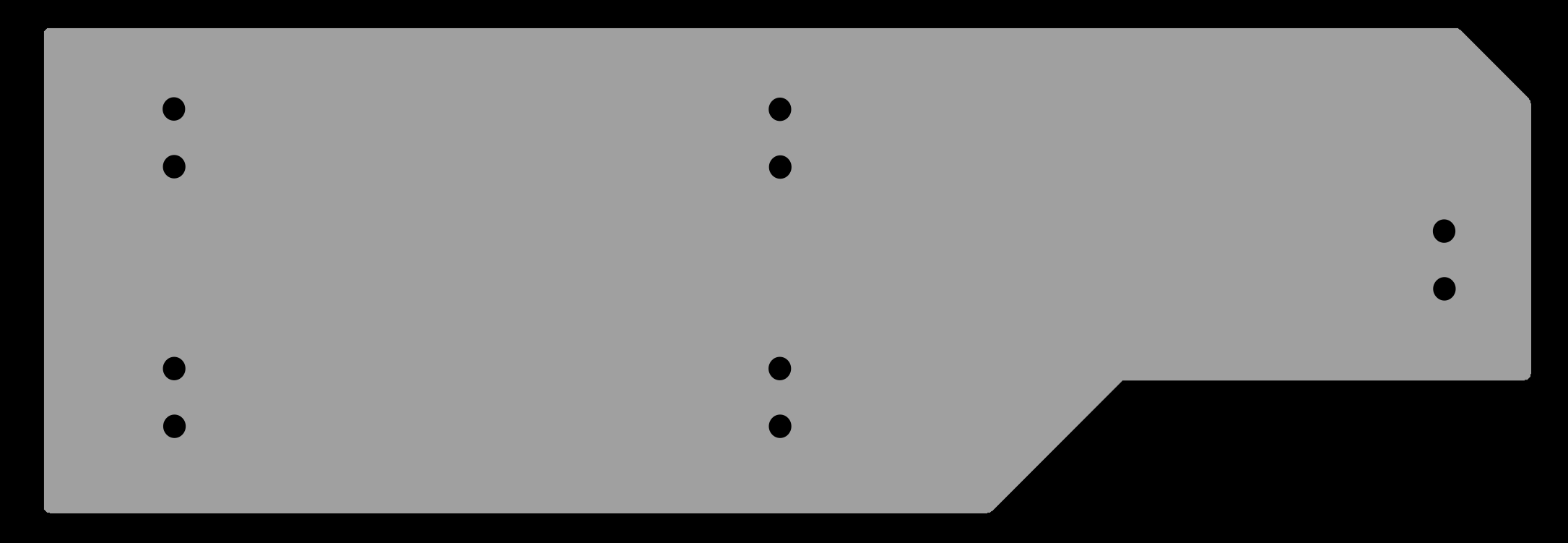
Board Images: GYRO9 MCU Board outline image here
GYRO9 MCU Board trace image here
GYRO9 Sensor Board outline image here
GYRO9 sensors Board trace image here
GYRO9 Power Board outline image here
GYRO9 Power Board trace image here
RML files: GYRO9 MCU Board Outline routing file here
GYRO9 MCU Board Trace routing file here
GYRO9 Sensor Board Outline routing file here
GYRO9 Sensor Board Trace routing file here
GYRO9 Power Board Outline routing file here
GYRO9 Power Board Trace routing file here
Code:
// Phanuwit Kanthatham, FabAcademy 2019, FabLab Kamakura
// Code based on original by Adafruit Strandtest and Sweep sketch by BARRAGAN  <http://barraganstudio.com>

#include <Servo.h>                //Servo library
#include <Adafruit_NeoPixel.h>
#ifdef __AVR__
#include <avr/power.h>         // Required for 16 MHz Adafruit Trinket
#endif

// Setup Lux Sensor Pin
const int LuxPin = A3;            // Sets constant variable for Arduino pin A3
// ...as the analog signal pin to Lux sensor
int dusk = 200;                   // Set threshold light level to trigger ON

// Set up Servos
Servo servoLeft;                  //Define ServoLeft as servo object
Servo servoRight;                 //Define ServoRight as servo object

const int SrvoPinL = 5;           // Sets PWM D5 as left servo pin
const int SrvoPinR = 6;           // Sets PWM D6 as right servo pin

int startPosL = 0;                // Variable for start angle for left servo
int startPosR = 180;               // Variable for start angle for right servo
int deployPos = 135;              // Variable for start angle for servo
int speed = 500;

// Set up NeoPixel
#define NPXLS_PIN    7          //Pin for Neopixel Sticks
#define NPXLC_PIN    8          //Pin for Neopixel Coins
#define NPXLS_COUNT 16          //LED count Neopixel Stick
#define NPXLC_COUNT 7           //LED count Neopixel Coin

// Declare NeoPixel stick object:
Adafruit_NeoPixel stick(NPXLS_COUNT, NPXLS_PIN, NEO_GRB + NEO_KHZ800);  //Neopixel Stick
Adafruit_NeoPixel coin(NPXLC_COUNT, NPXLC_PIN, NEO_GRB + NEO_KHZ800);   //Neopixel Coin

int pauseS = 50;
int pauseF = 30;
int bright = 50;

// Neopixel Functions in GYRO9 Project

// ColorWipe Function:
// Fill stick pixels one after another with a color. stick is NOT cleared
// first; anything there will be covered pixel by pixel. Pass in color
// (as a single 'packed' 32-bit value, which you can get by calling
// stick.Color(red, green, blue) as shown in the loop() function above),
// and a delay time (in milliseconds) between pixels.

// ColorWipe for Stick:
void colorWipeS(uint32_t color, int wait) {
  for (int i = 0; i < stick.numPixels(); i++) { // For each pixel in stick...
    stick.setPixelColor(i, color);            //  Set pixel's color (in RAM)
    stick.show();                             //  Update stick to match
    delay(wait);                               //  Pause for a moment
  }
}

// ColorWipe for Coin:
void colorWipeC(uint32_t color, int wait) {
  for (int i = 0; i < coin.numPixels(); i++) { // For each pixel in stick...
    coin.setPixelColor(i, color);             //  Set pixel's color (in RAM)
    coin.show();                              //  Update stick to match
    delay(wait);                              //  Pause for a moment
  }
}

// Theater Marquis Function:
// Theater-marquee-style chasing lights. Pass in a color (32-bit value,
// a la stick.Color(r,g,b) as mentioned above), and a delay time (in ms)
// between frames.

// Theater Marquis for Stick:
void theaterChaseS(uint32_t color, int wait) {
  for (int a = 0; a < 10; a++) { // Repeat 10 times...
    for (int b = 0; b < 3; b++) { //  'b' counts from 0 to 2...
      stick.clear();         //   Set all pixels in RAM to 0 (off)
      // 'c' counts up from 'b' to end of stick in steps of 3...
      for (int c = b; c < stick.numPixels(); c += 3) {
        stick.setPixelColor(c, color); // Set pixel 'c' to value 'color'
      }
      stick.show(); // Update stick with new contents
      delay(wait);  // Pause for a moment
    }
  }
}

// Theater Marquis for Coin:
void theaterChaseC(uint32_t color, int wait) {
  for (int a = 0; a < 10; a++) { // Repeat 10 times...
    for (int b = 0; b < 3; b++) { //  'b' counts from 0 to 2...
      coin.clear();         //   Set all pixels in RAM to 0 (off)
      // 'c' counts up from 'b' to end of stick in steps of 3...
      for (int c = b; c < coin.numPixels(); c += 3) {
        coin.setPixelColor(c, color); // Set pixel 'c' to value 'color'
      }
      coin.show(); // Update stick with new contents
      delay(wait);  // Pause for a moment
    }
  }
}

// setup() function...runs once at startup

void setup() {
  Serial.begin(9600);             // Starts up serial communication

  // Set up Lux sensor here...
  pinMode(LuxPin, INPUT);         // Sets the A3 pin where the Lux sensor
                                  // ...is connected as INPUT


  // Set up Servos here...
  servoLeft.attach(SrvoPinL);     // Attaches servoLeft to digital pin 5
  servoRight.attach(SrvoPinR);    // Attaches servoRight to digital pin 9

  servoLeft.write(startPosL);      // Sets servo start position
  servoRight.write(startPosR);     // Set servo start position


  // Set up Neopixels here...
  stick.begin();           // INITIALIZE NeoPixel stick object (REQUIRED)
  stick.show();            // Turn OFF all pixels ASAP
  stick.setBrightness(bright); // Set BRIGHTNESS to about 1/5 (max = 255)


  coin.begin();           // INITIALIZE NeoPixel coin object (REQUIRED)
  coin.show();            // Turn OFF all pixels ASAP
  coin.setBrightness(bright); // Set BRIGHTNESS to about 1/5 (max = 255)

  // Run Neopixel Startup Routine
  colorWipeS(stick.Color(255,   0,   0), pauseS); // Red
  colorWipeC(coin.Color(255,   0,   0), pauseS); // Red

  colorWipeS(stick.Color(  0, 255,   0), pauseS); // Green
  colorWipeC(coin.Color(  0, 255,   0), pauseS); // Green

  colorWipeS(stick.Color(  0,   0, 255), pauseS); // Blue
  colorWipeC(coin.Color(  0,   0, 255), pauseS); // Blue

  delay(1000);                              // wait 1secs
}

// loop() function -- runs repeatedly as long as board is on

void loop() {
  int LuxVal = analogRead(LuxPin);   // Reads analog values from lux sensor

  Serial.print(LuxVal);
  Serial.print('\n');
  delay(50);

  if (LuxVal > dusk) {         // Not Dark...

    // Fill Black along the length of the stick...
    colorWipeS(stick.Color(0,   0,   0), pauseS); // Black
    colorWipeC(coin.Color(0,   0,   0), pauseS); // Black

    // Servo at Start Position when bright
    servoLeft.write(startPosL);        // Returns left servo spindle to home...zero angle
    servoRight.write(startPosR);       // Returns Right servo spindle to home...zero angle
    delay(speed);                        // Wait for servos to reach position


  }
  else { // dark

    //      Do a theater marquee effect in various colors...
    theaterChaseS(stick.Color(127,   0,   0), pauseF); // Red, half brightness
    theaterChaseC(coin.Color(127,   0,   0), pauseF); // Red, half brightness

    // Servo to full Deploy position
    servoLeft.write(deployPos);       // Rotates servo spindle to full deploy position
    servoRight.write(startPosR - deployPos);   // Rotates servo spindle to full deploy position
    delay(speed);

  }
}