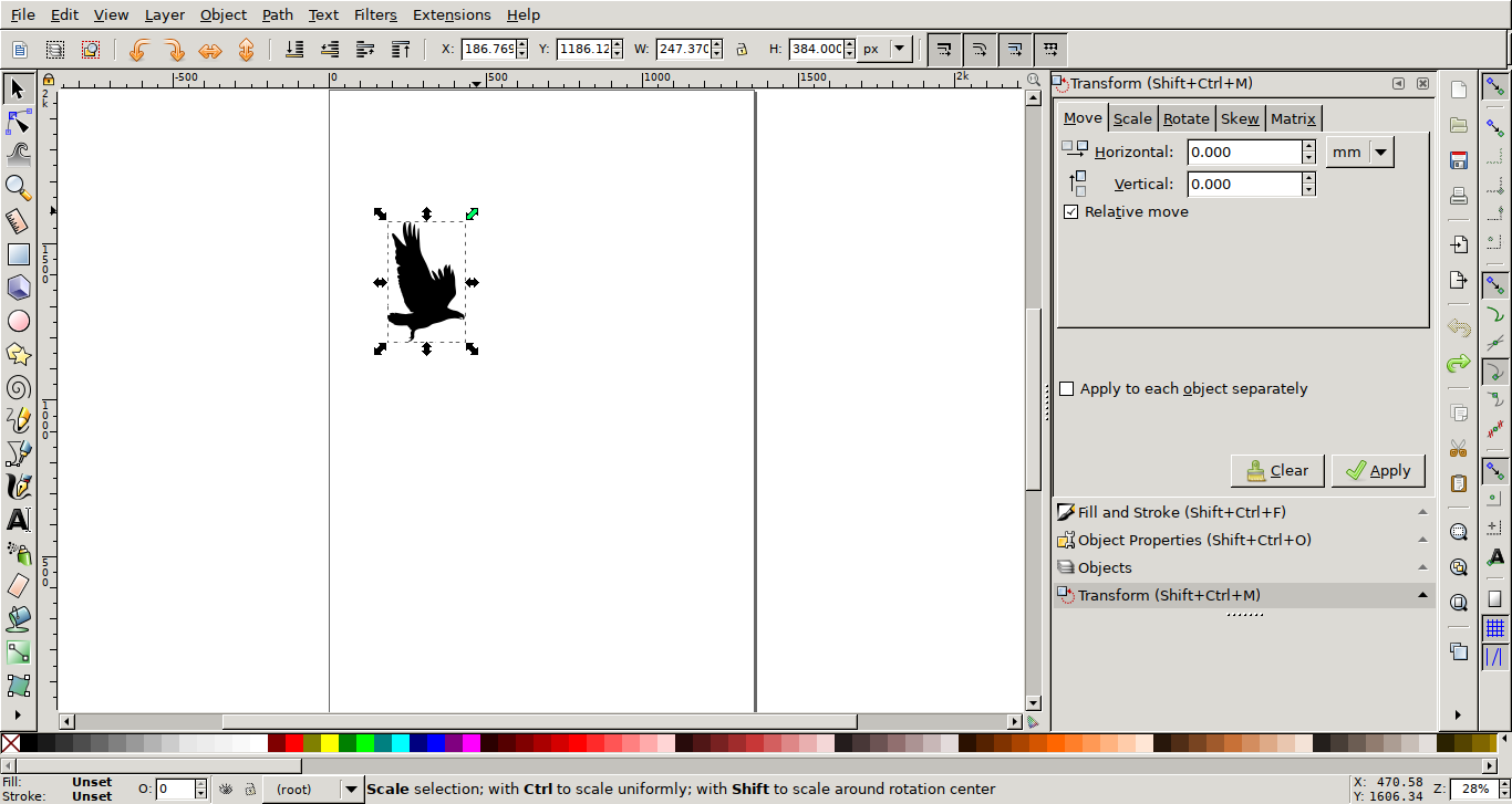
For the first part of the exercise I decided to cut a public domain vector image. I found a nice single color silhouette of a flying bird on publicdomainvectors.org. I rescaled it in Inkscape (just selecting the element, dragging it from one of the corners while keeping the ctrl key pressed) and used Robocut to cut it using the Silhouette Portrait Vinyl cutter.
I compiled Robocut according to the instructions provided with the source code and executed it as root using sudo ./robocut Without root permissions it would not detect the cutter.
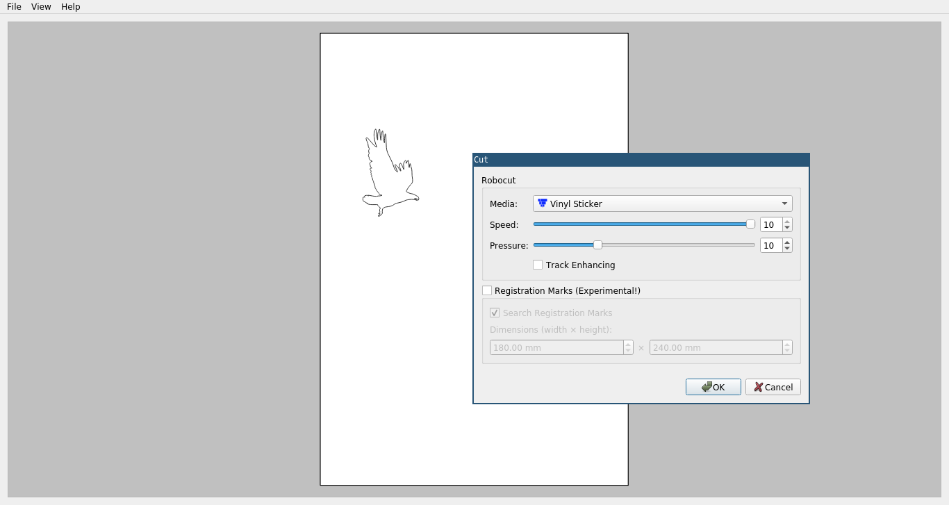
I connected the cutter to my computer and inserted the blade into the holder. Now I used some glue to place the vinyl sheets on to the cutting foil that acts as a base to hold the material. Using the up button on the control panel I let the cutter pull it in a little bit so it has a good grip and there are no kinks or bends in the material. In the software I just loaded the SVG file I wanted to use, hit "File -> Cut", selected the right material - in my case the preselected "Vinyl Sticker" was already correct - and confirmed by pressing "OK".
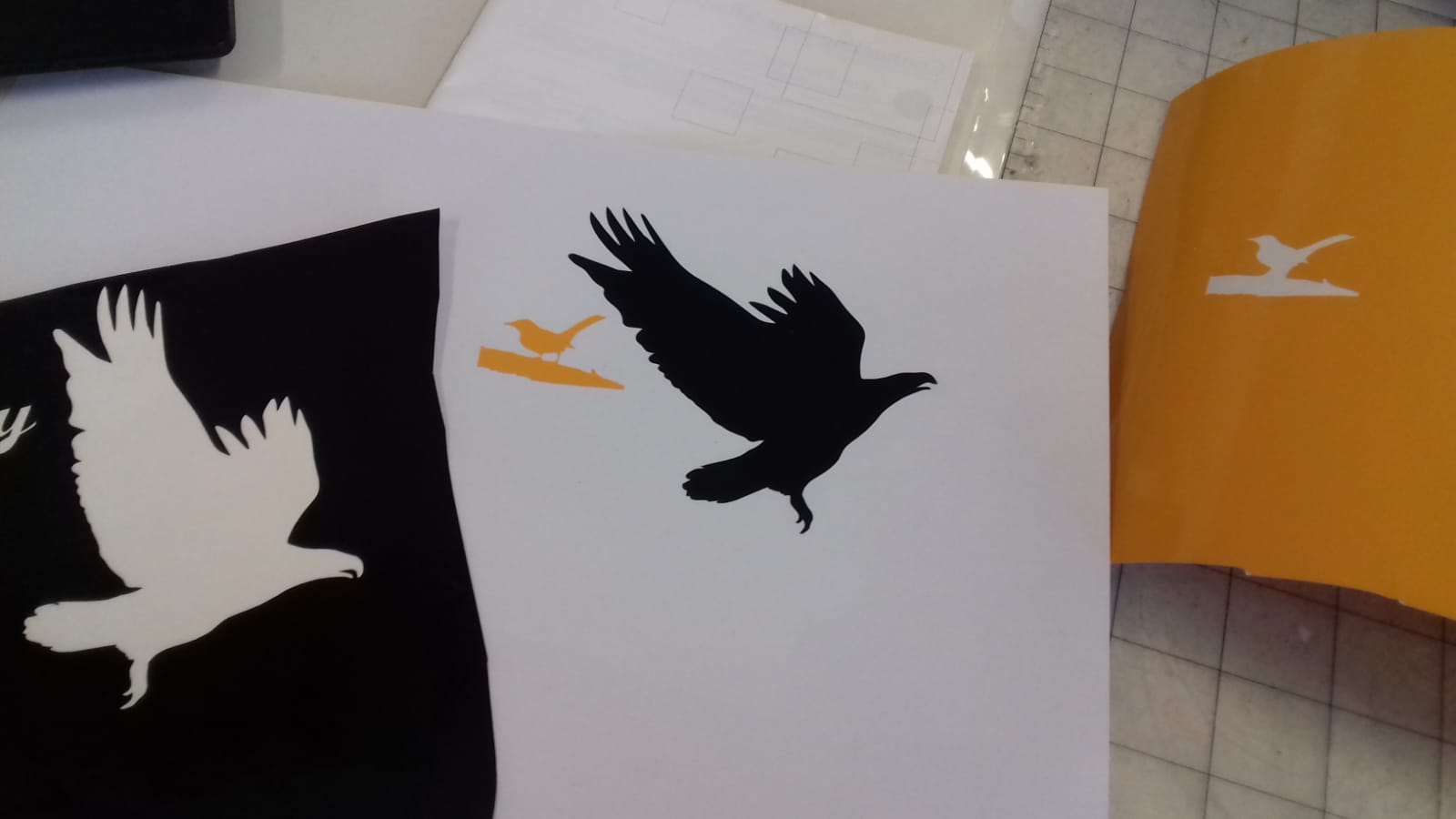
I also tested a smaller silhouette with very fine legs. The material was surprisingly strong. A very small link at the left leg broke, but the other one stayed in one piece.
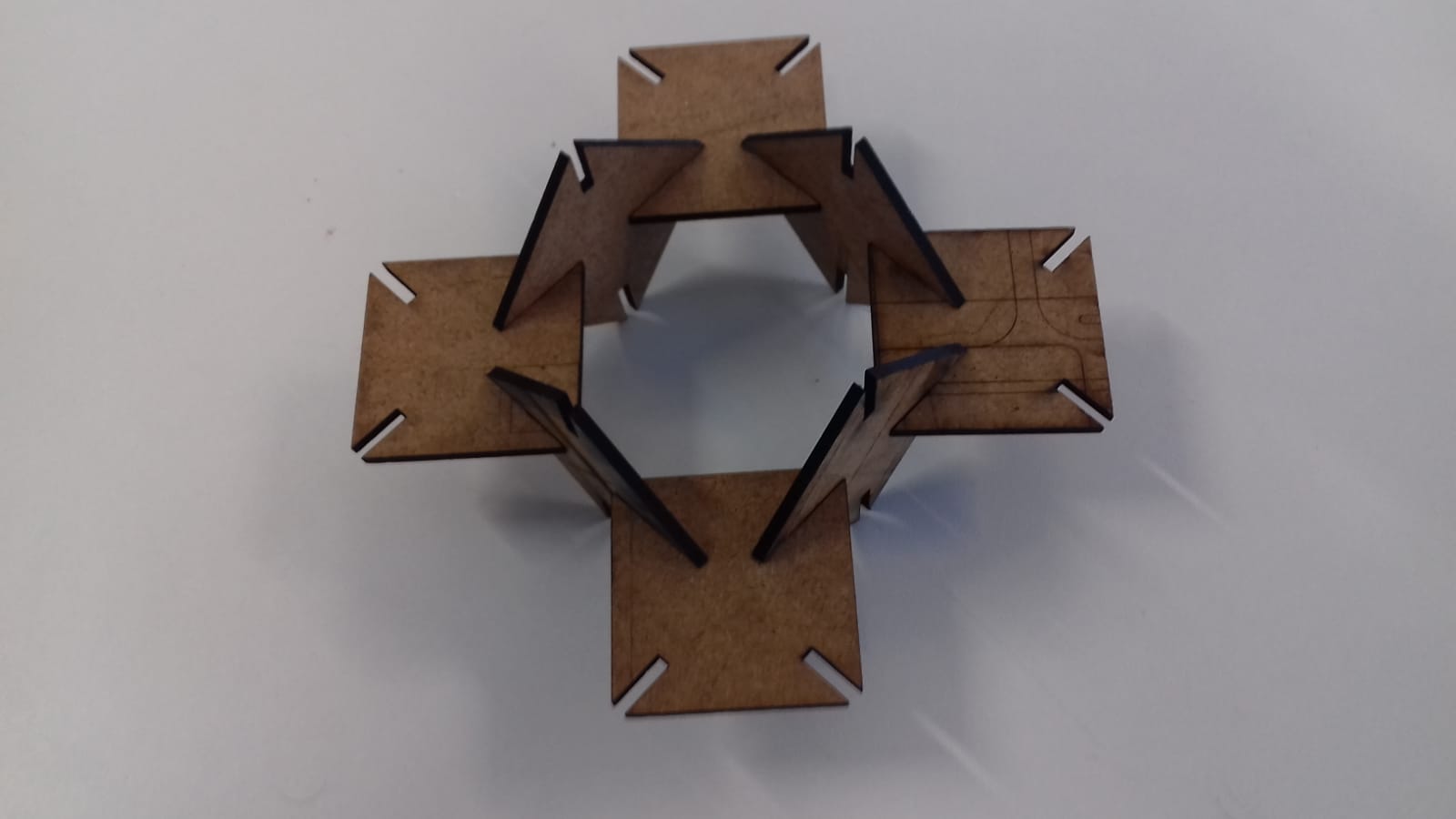
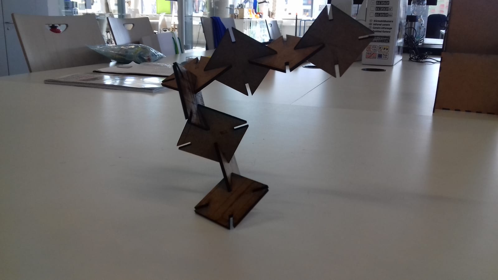
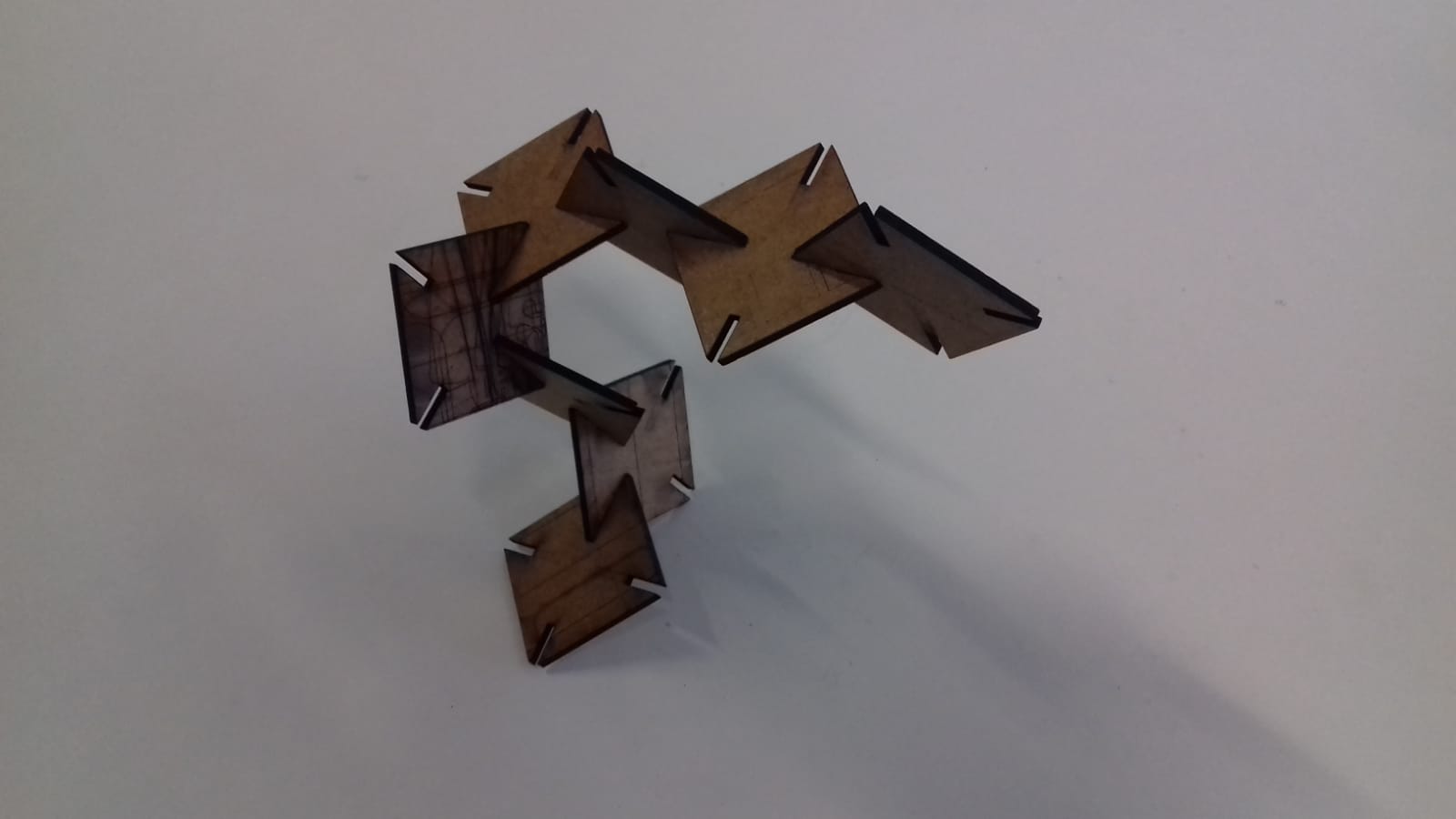
My parametric design for the laser cutter was created in Fusion 360. I used this instead of openSCAD because I never used it's parametric modelling features before. I decided to start with a quadratic base shape with four slots for connections in the corners. First I started with a different design, but that did not turn out to be versatile enough.
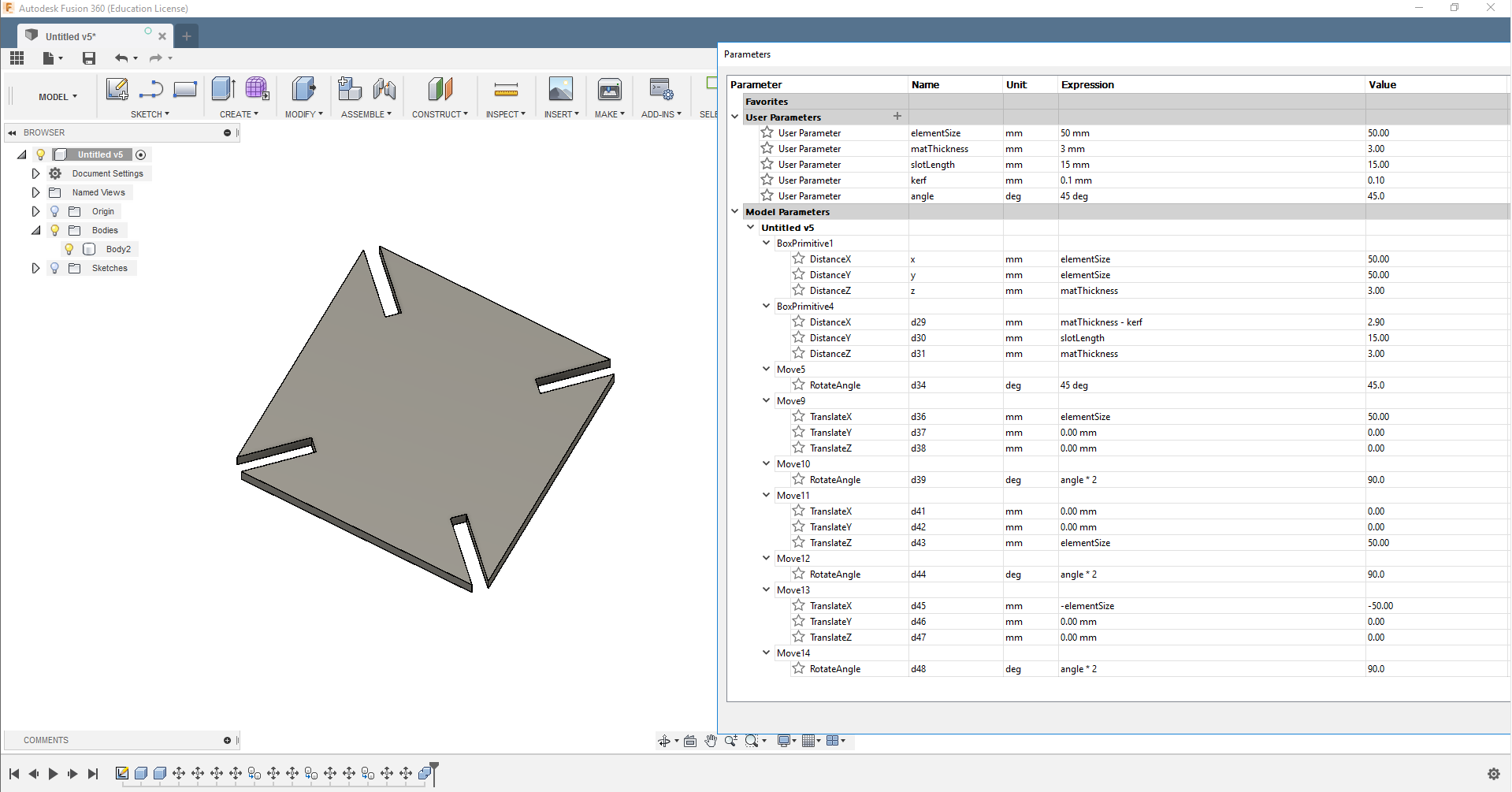
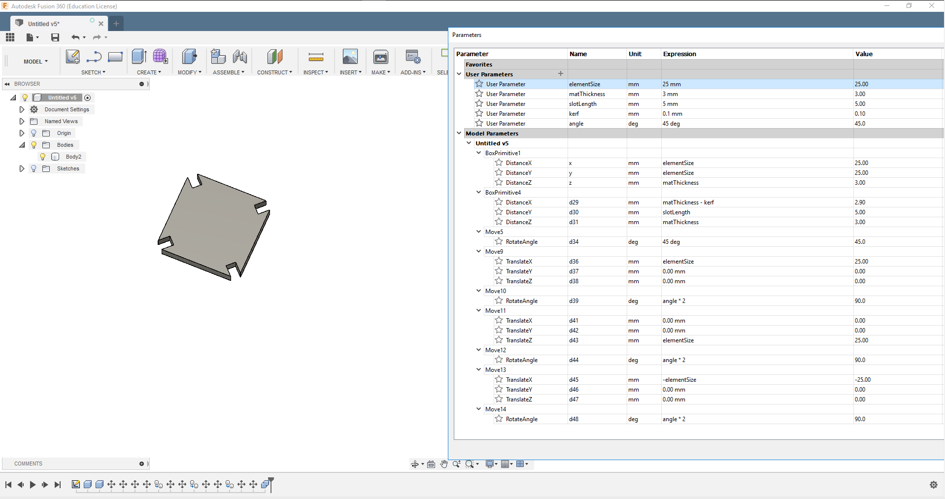
The base shape is simply a square (with one parameter for the length of the sides and one for the material thickness). In each of the corners there is an element that cuts in the notches for assembly. I started off with creating a box using the tool from the "Create" menu and then opening the "Parameters" window to set it's width and height to a user defined variable. I called this variable "elementSize". Now only this variable needs to be changed and the element will scale symmetrically. The notches for connecting the elements have separate variables, because they are dependent on the thickness of the material, the kerf created by the laser cutter and the desired length. (Their width is the thickness of the material minus the kerf, in this case I configured a kerf of 0.1mm.) The angle will always be 45 or 2x45°, so that variable is only defined for convenience. The offset of the notches is simply the elementSize variable.
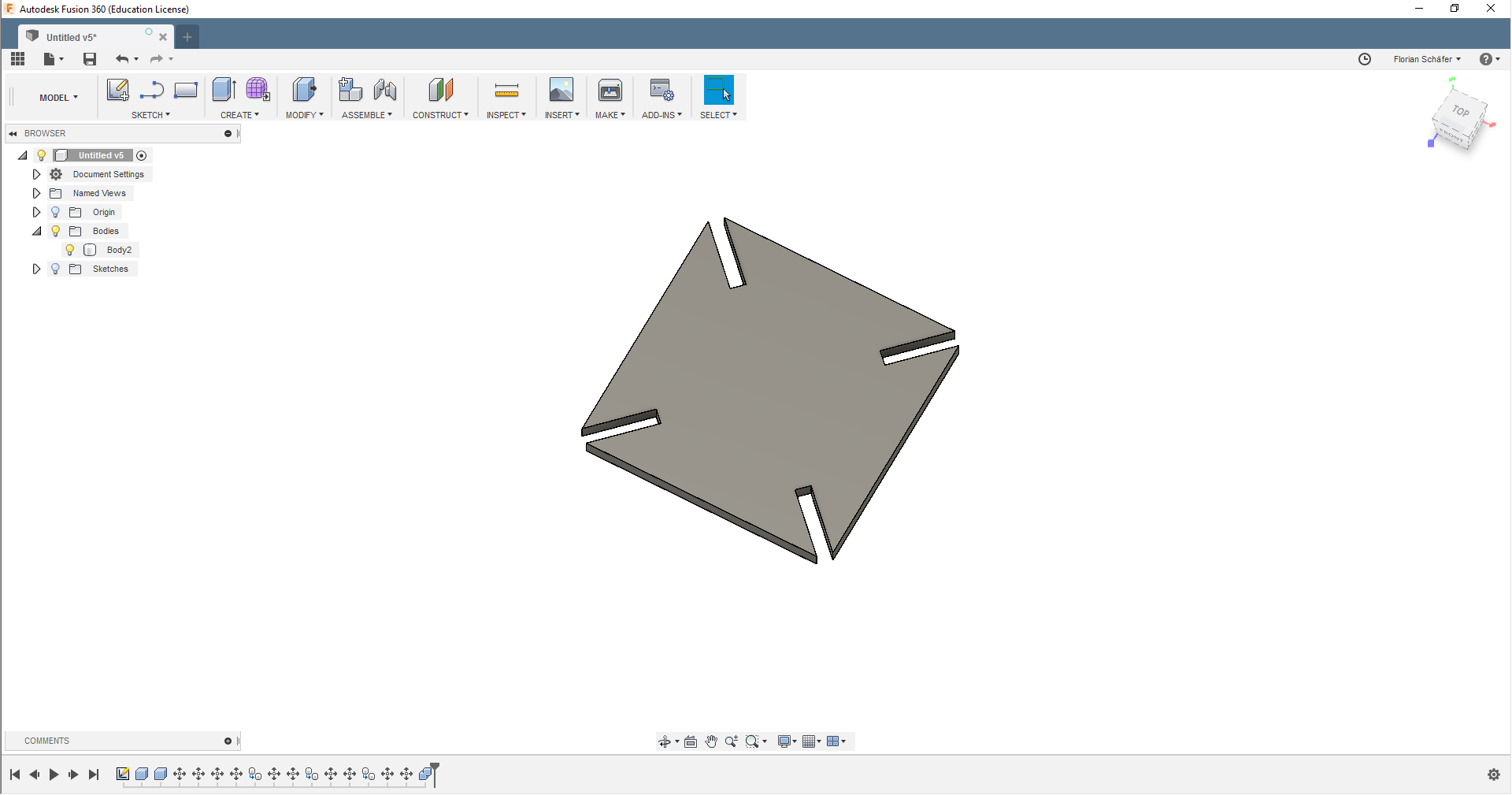
To test if all parameters are working with each other I changed the size.
I exported the face of the model using the plugin DXF for Laser by Ross Korsky, duplicated it a few times using a vector graphic editor and loaded it into VisiCut.
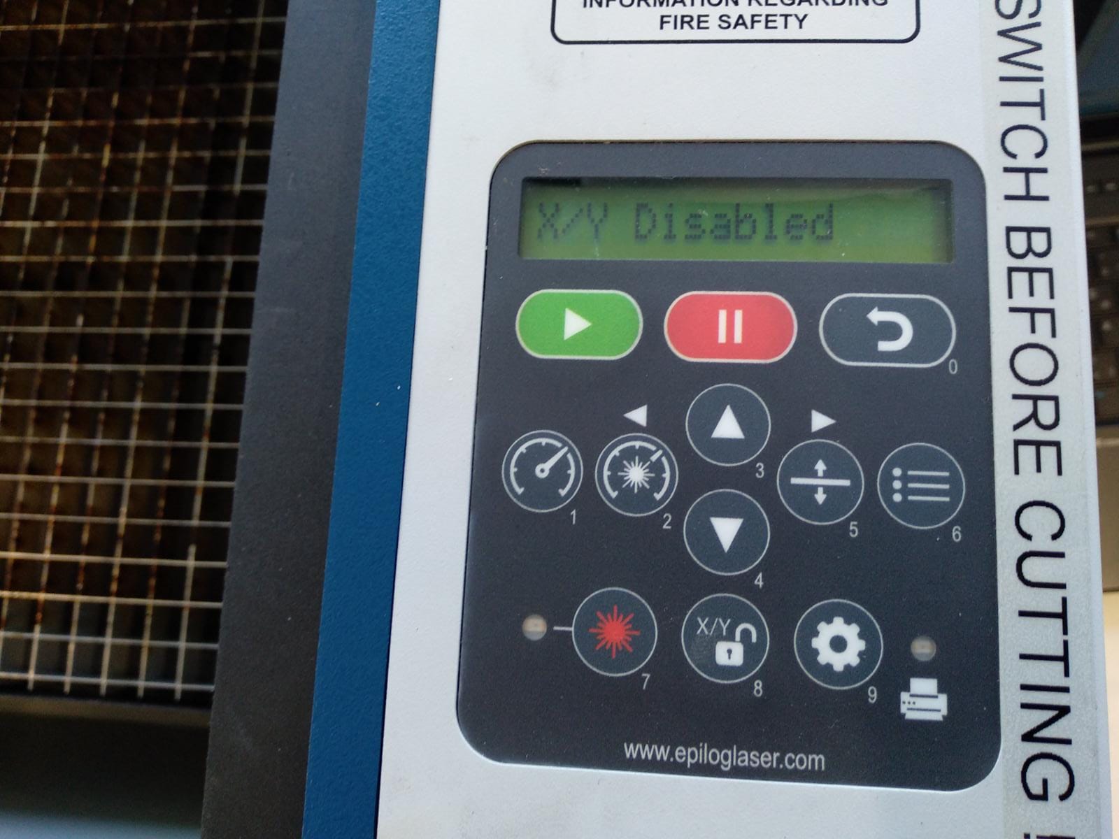
First step of operating the laser cutter is setting the home point using the "XY-Unlock" button to make the head moveable and then reach into the machine and move it to the desired 0,0 point. To be a little more precise the laser pointer can be activated, showing the exact point on the stock. To confirm and relock the device press the green button.
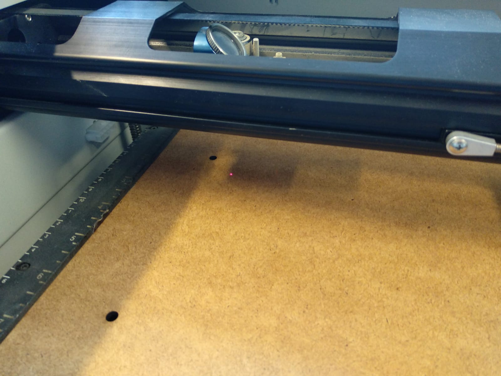
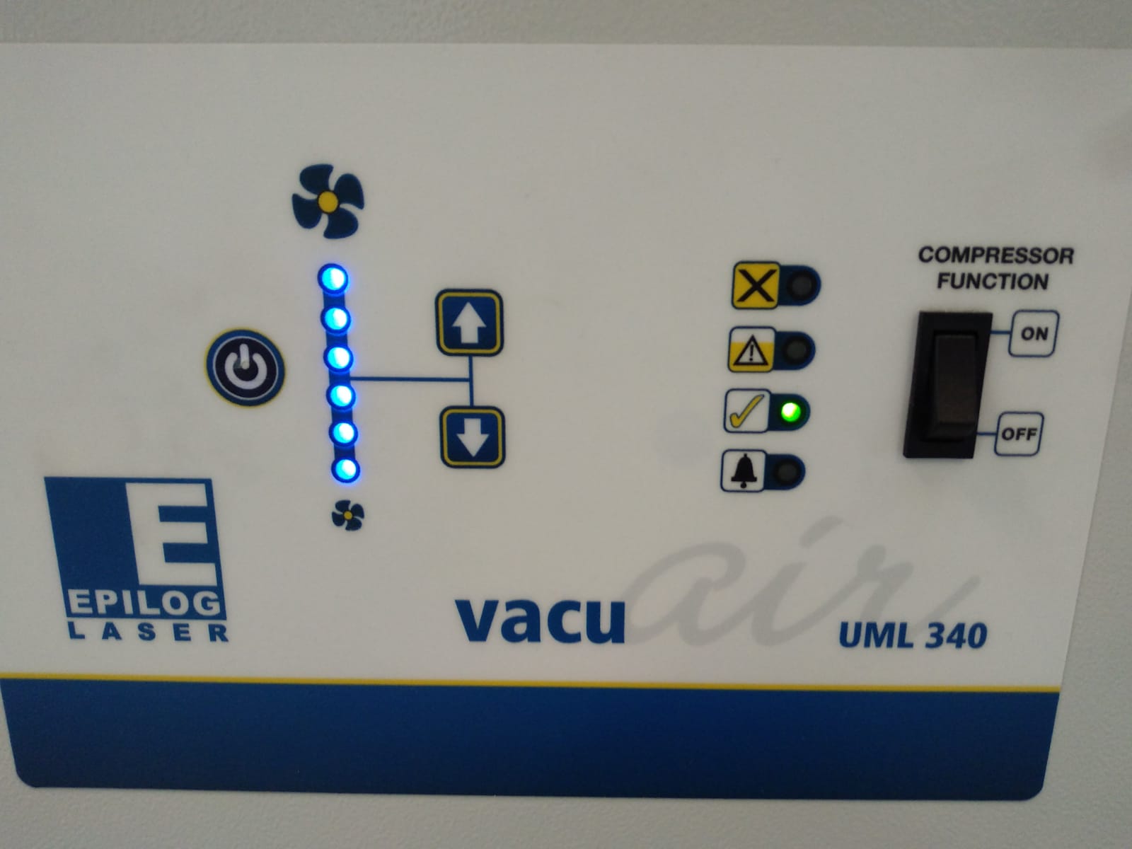
Afterwards the focus is set using the "Height" button (number 5) to move the plate of the cutter up or down. The correct focus is set when the focusing help is barely touching the stock. Now the SVG file can be loaded into VisiCut. The settings can be defined for each layer and then send to the machine using the "Execute" button. Afterwards the job can be selected on the machine an started with the green button. Before doing that it is important to close the cover and turn on the filtering/vacuum system below the machine. Without the filtering a lot of smelly smoke will be released and the stock might start burning. Even with the vacuum there is a risk of fire, so keep an eye on the machine while it's running.
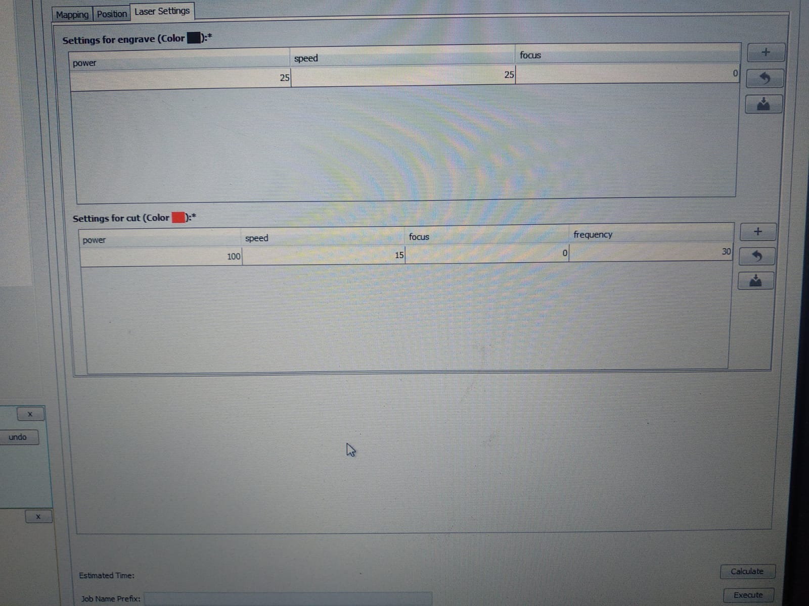
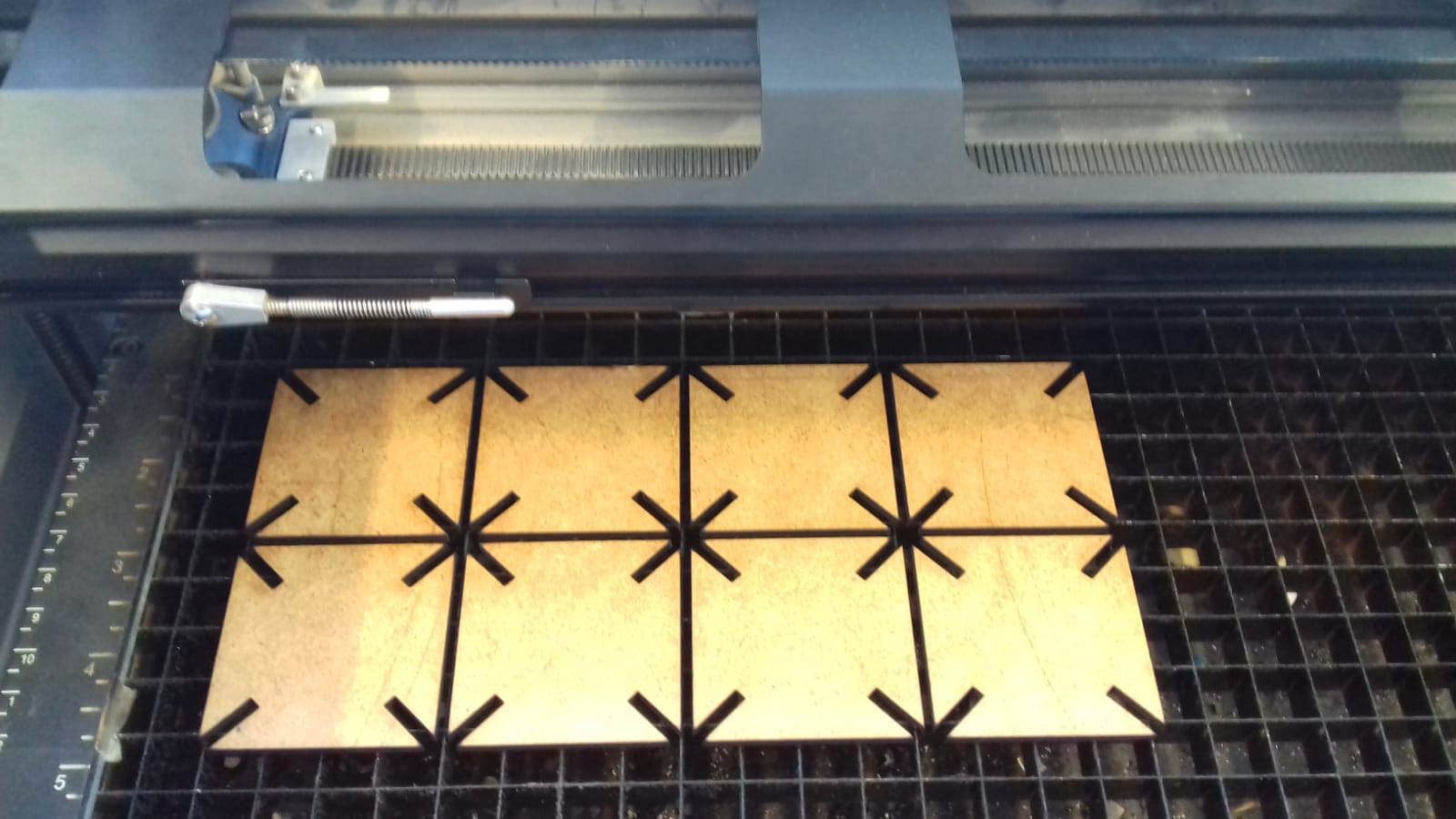
My material of choice was 3mm MDF. On the first try I used the following settings on the Epilog Zing:
Power 100, Speed 10, Freq 20.
This left a lot of burn marks and a very large amount of kerf, much more than the 0.1mm I set in Fusion, so I changed it to Power 70, Speed 11, Freq 30.
Testing engraving with a smaller design

Now the pieces would hold together fine. Some of them a little loose, but still stable.