Group Assignment: Electronics Production
For this exercise I created an ISP using the design from http://fab.cba.mit.edu/classes/863.16/doc/projects/ftsmin/index.html. It is named "FabTinyISP Minimal". I decided to use this design because I liked that it is minimalistic, doesn't use too many optional parts, doesn't need a USB cable and is quite compact.
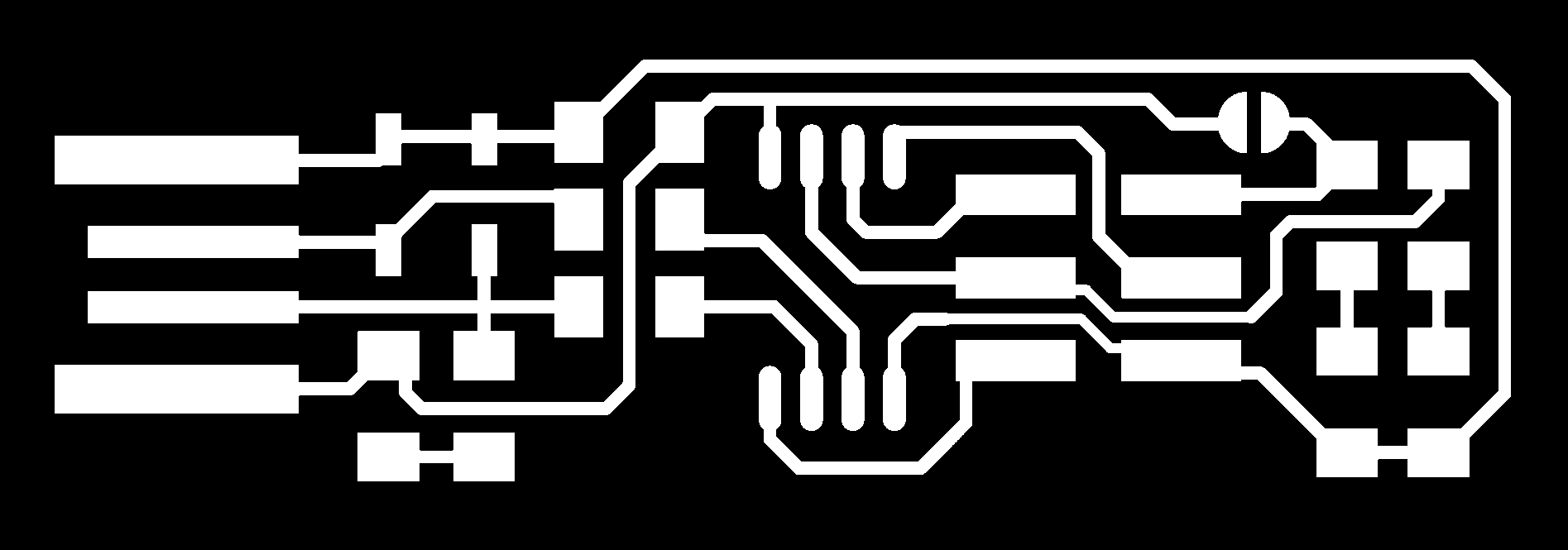
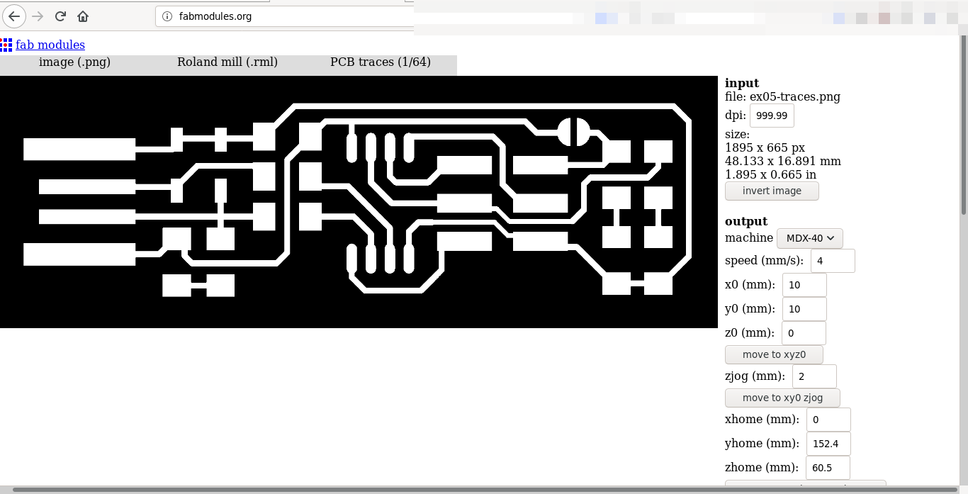
First I downloaded the images of the PCBs traces and outlines and converted them into GCODE for the Roland Mill MDX-40A using fabmodules.org. First I selected "image (.png)" as input format, "Roland mill (.rml)" as output format and "PCB traces (1/64)" as process. It's also important to enter the right dpi value, otherwise the result will have a completely different scale. Now the right mill model - in my case MDX-40 - can be selected in the dropdown menu. This generates some default settings that can be modified now, mainly depending on the tool that's used. The same process is repeated for the outlines.
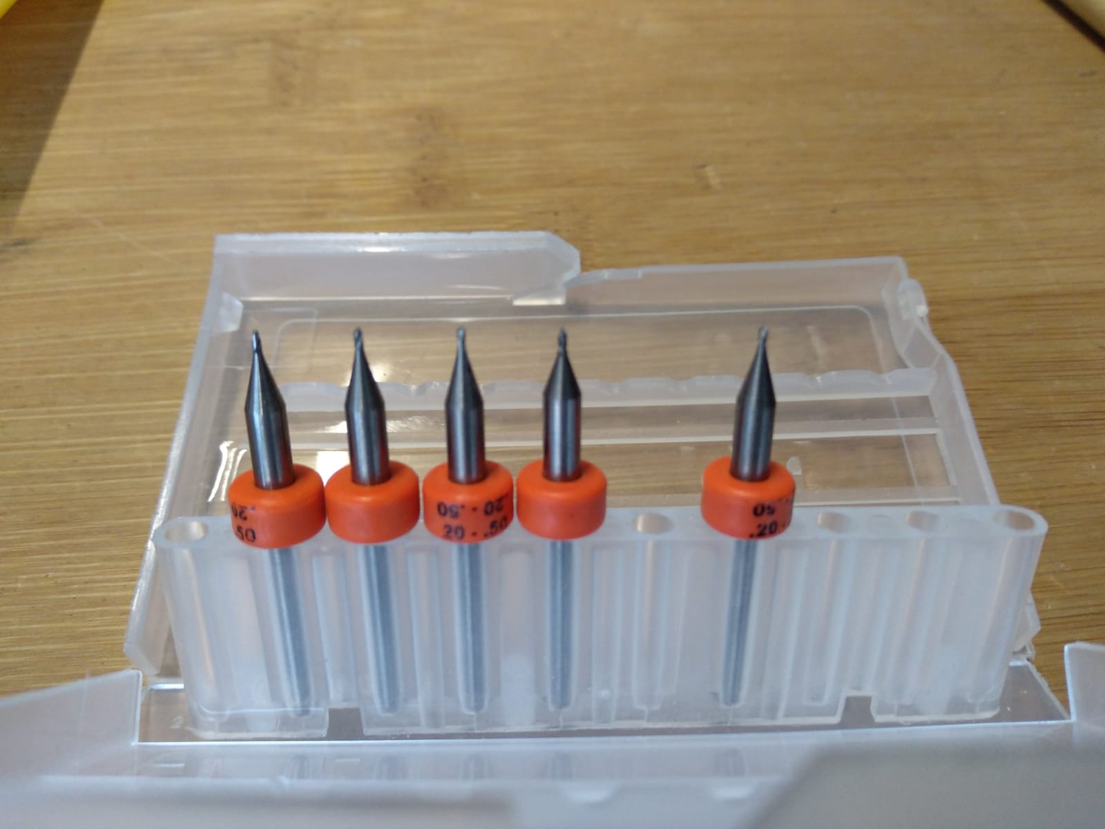
For engraving the traces I used a 0.2mm head, for cutting the outline a 1mm head. First I did not have enough copper removed at the USB connector, so I turned up the number of offsets to 10, with a 55% overlap. Now the mill removed enough of the copper so I could remove the rest by hand.
The settings I used for engraving were: speed 4mm/s, zjog 2mm, cut depth 0, tool diameter 0.2
The settings I used for cutting were: speed 1mm/s, zjog 5mm, cut depth 1.9, tool diameter 1 and only 1 offset.
As mentioned above the tool used for engraving the traces has 0.2mm diameter. The tool is changed using a pair of wrenches. The tool holder is slowly released without dropping the old tool. Now the tool can be removed and the new one can be installed, tightening the holder using the wrenches.
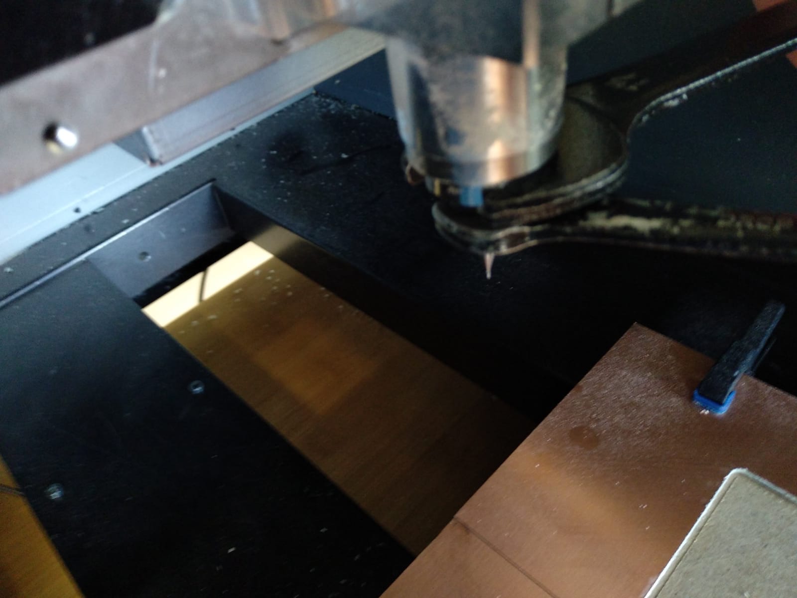
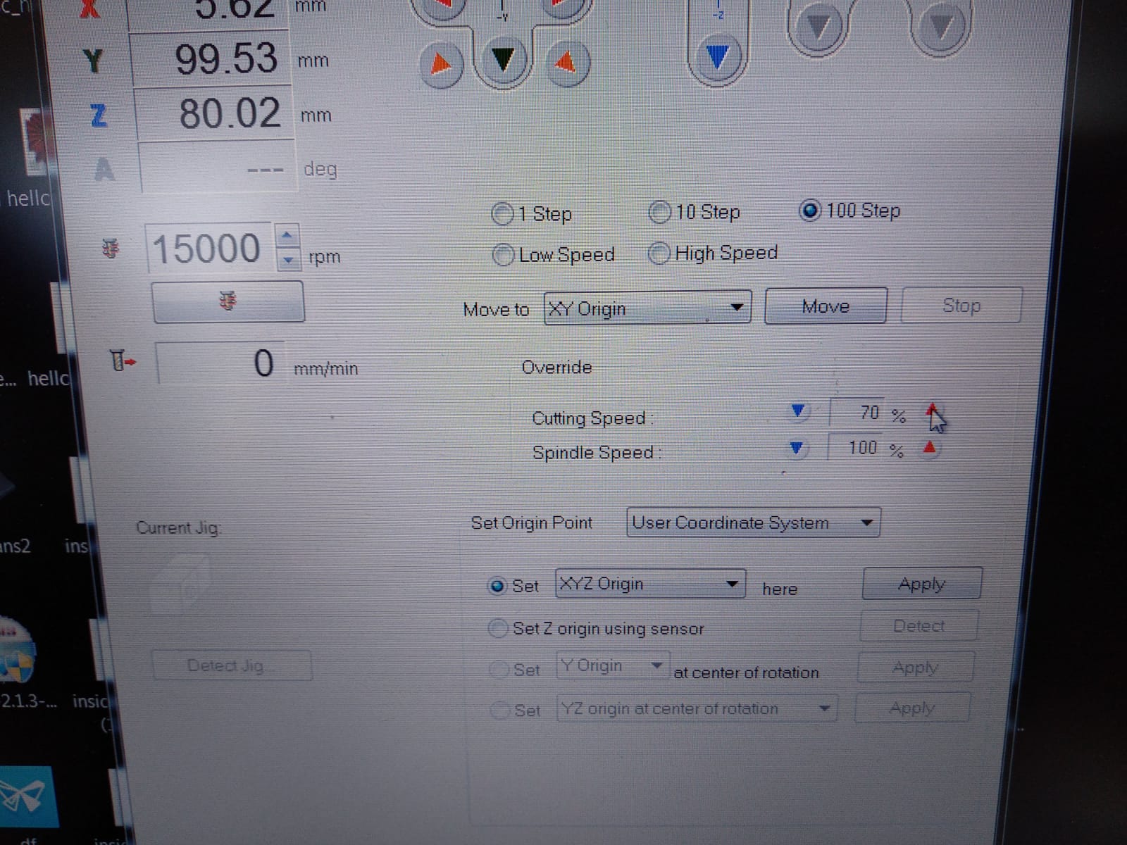
Next the X, Y and Z zero positions have to be set. This is similiar to what was done when using the laser cutter. The tool is moved using buttons in the VPanel software. For fine tuning the speed can be reduced down to only one step at a time. When setting the Z postion we have to be really precise to get nice traces and also not damage the tool. I used a multimeter held to the copper plate and the tool to test for contact, moving only one step at a time. After getting contact I started the spindle, moved the tool down another one or two steps and then set the Z position to zero. Setting the zero point is done by selecting the correct axis from the "Set Origin" dropdown menu and clicking "Apply".
Now the job can be executed by pressing "Cut", selecting the file with the GCODE and pressing "Output". The same will be repeated for the outlines using the 1mm tool. When both jobs are done the board can be removed using a screwdriver.
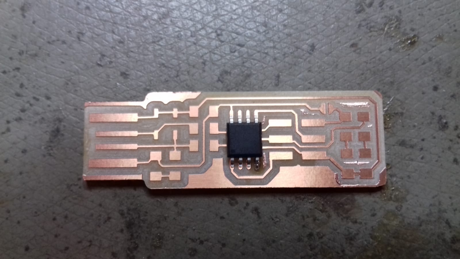
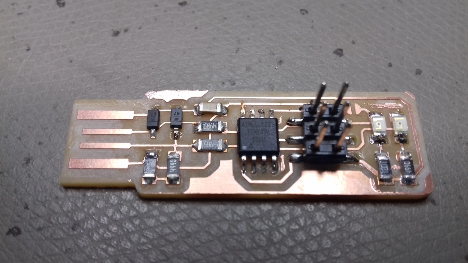
Next I soldered all components. A list can be found at the link above. Especially for the zener diodes and the microcontroller it was very helpful to use enough flux. At this point I did not yet put solder on the USB contacts, because I wanted to test if it actually is necessary for my USB ports. The board contains a jumper, which is used to connect the VPROG pin of the ISP header. After connecting my programmer I noticed that I probably didn't need it at all, because I didn't connect that pin when programming.
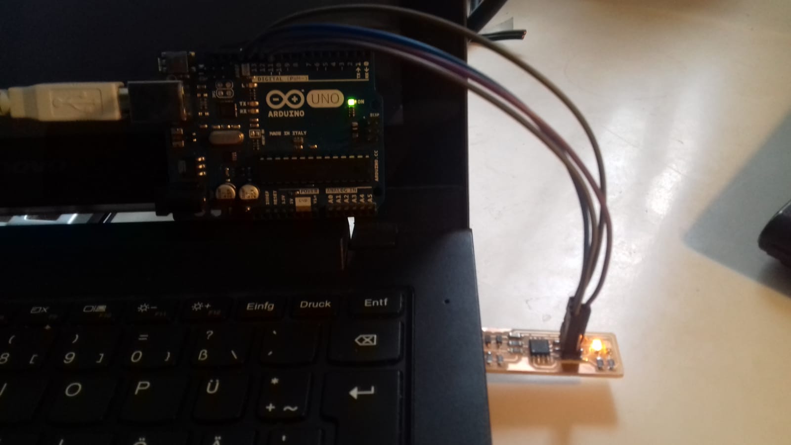
I used an Arduino as ISP to programm the board. For that I had to adjust the makefile coming with the firmware. The firmware was created by by Chris Chung and is based on work by Christian Starkjohann and Dick Streefland, and is licensed under GPLv2. To get it to work I changed the avrdude commands to use the correct port - in my case /dev/ttyACM0 - and a baudrate of 19200 baud. The flag to specify the baudrate is -b. I changed the programmer to stk500v1 because the arduino programmer never worked for me.
Makefile
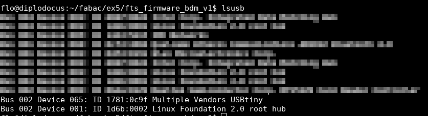
Next I connected SCK, MISO, MOSI and RST according to the schematics, build the firmware using make and flashed it using make flash, while having the PCB connected to my USB port to power it up. Next I set almost all of the fuses using make fuses and tested the usb connections afterwards. The device showed up in the lsusb list, as well as in the dmesg log.
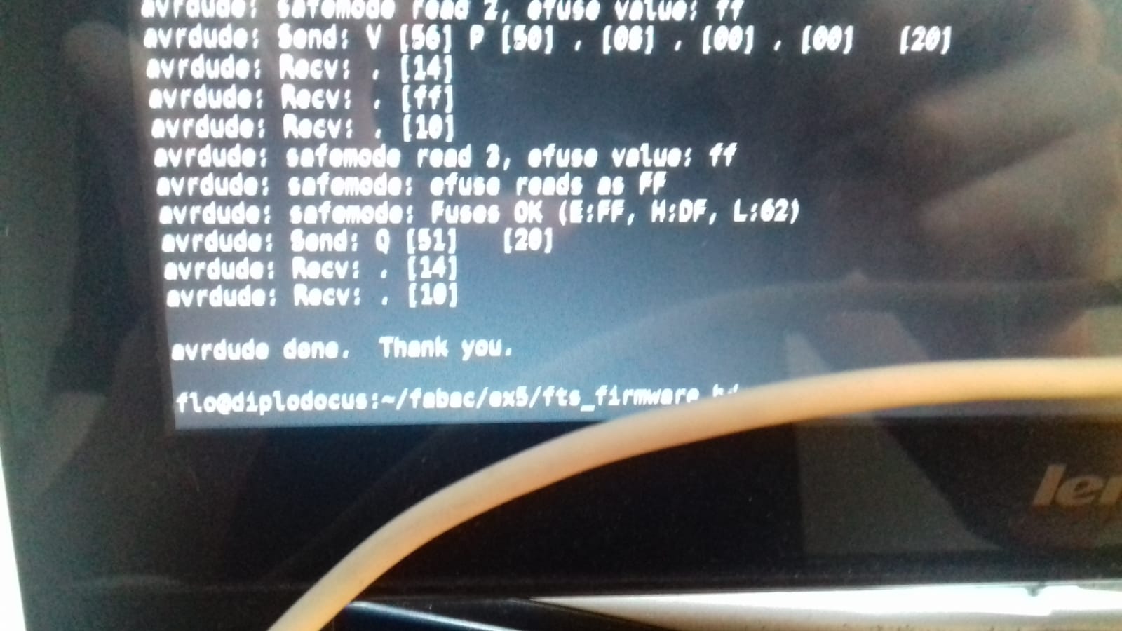
Now beeing sure that the USB connection works fine I could set the final fuse, making the RST pin into a standard GPIO pin. The command for that was make rstdisbl.
The very last step was to remove the solder on the jumper to put the ISP into it's standard mode of operation.
Especially for soldering there is some room for improvement, but that is a matter of exercise. Another thing I would do different is I would set the number of offsets to a higher number or even -1 to mill away all unused copper, so I don't have to remove parts of it by hand.
⬅ Back to overview