Final Project
So for my final project, I want to build a force feedback glove to work ín conjunction with vr headsets and the motioncontroller "leap motion".
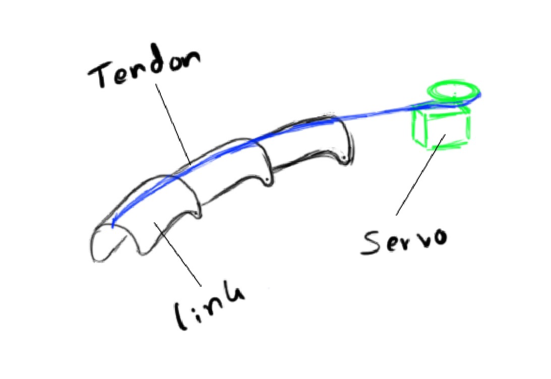
The plan is to restrict the user's finger's movement whenever he grabs something in vr, so it feels like he is grabbing it in real life as well.
This is an illustration of my first idea, as it is also in the "principles and practices"- assignment.
At first work on this project only consisted of research on how to actually restrict any movement.
The first idea was to do something with pneumatics. I found out, that if you have a flexible container with some kind of powdery substance inside of it and pull a vacuum on it, it turns solid. Therefore the idea was to put such containers on each and every joint of the fingers and be able to control them individually.
however this idea came to an abrubt halt, when we tried it and noticed, that it pretty much doesn't provide any feedback whatsoever.
Unfortunately the pictures and video of that happening went missing, so here is where I got the idea originally.
The next idea came from my laptop, it's display can detach with a muscle wire mechanism so I researched further into the so called "shape memory alloys" and came across nitinol. Which is supposed to contract when current is applied to it and expand to it's original length when it cools back down again.
I thought that this was perfect for my application, since I could just have a piece of it at each joint and contract/expand it however I want.
But before I went and designed something, I decided to first experiment with it for a while. Which turned out to be a huge timesaver, because as it turns out The nitinol gets REALLY HOT when applying the current needed for it to contract at the rate I wanted it to. And also it doesn't go back to it's original length without external force, which could have been provided by the user's hand, but way too much force was needed so that plan had to go as well.
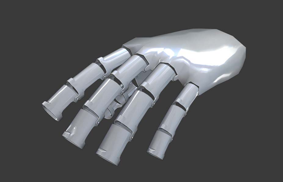
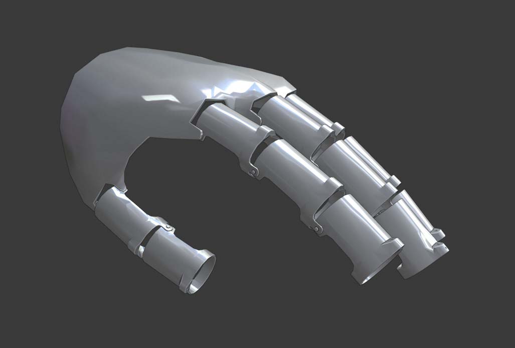
So at that point I turned back to my original idea, which is just a machanism using fishingwire tedons and servos to lock them in place at an arbitrary point. As that seemed plausible and I was sure it would simply work, I had gone ahead and started designing the exo-skeleton that I want to mount everything to.
As you can see here, this is the first design I made in Blender (more about blender) to get a better Idea of wether or not it was going to work.
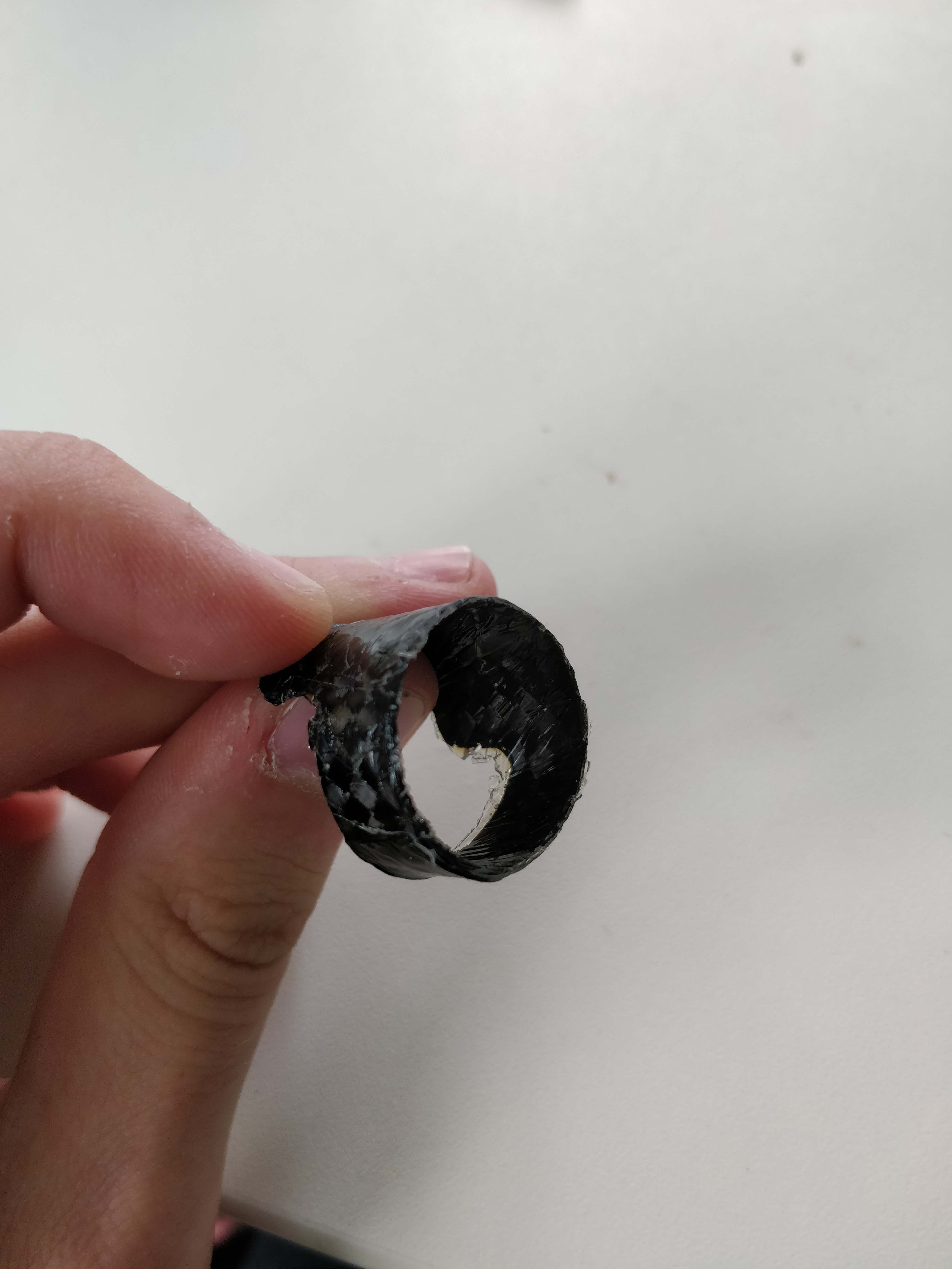
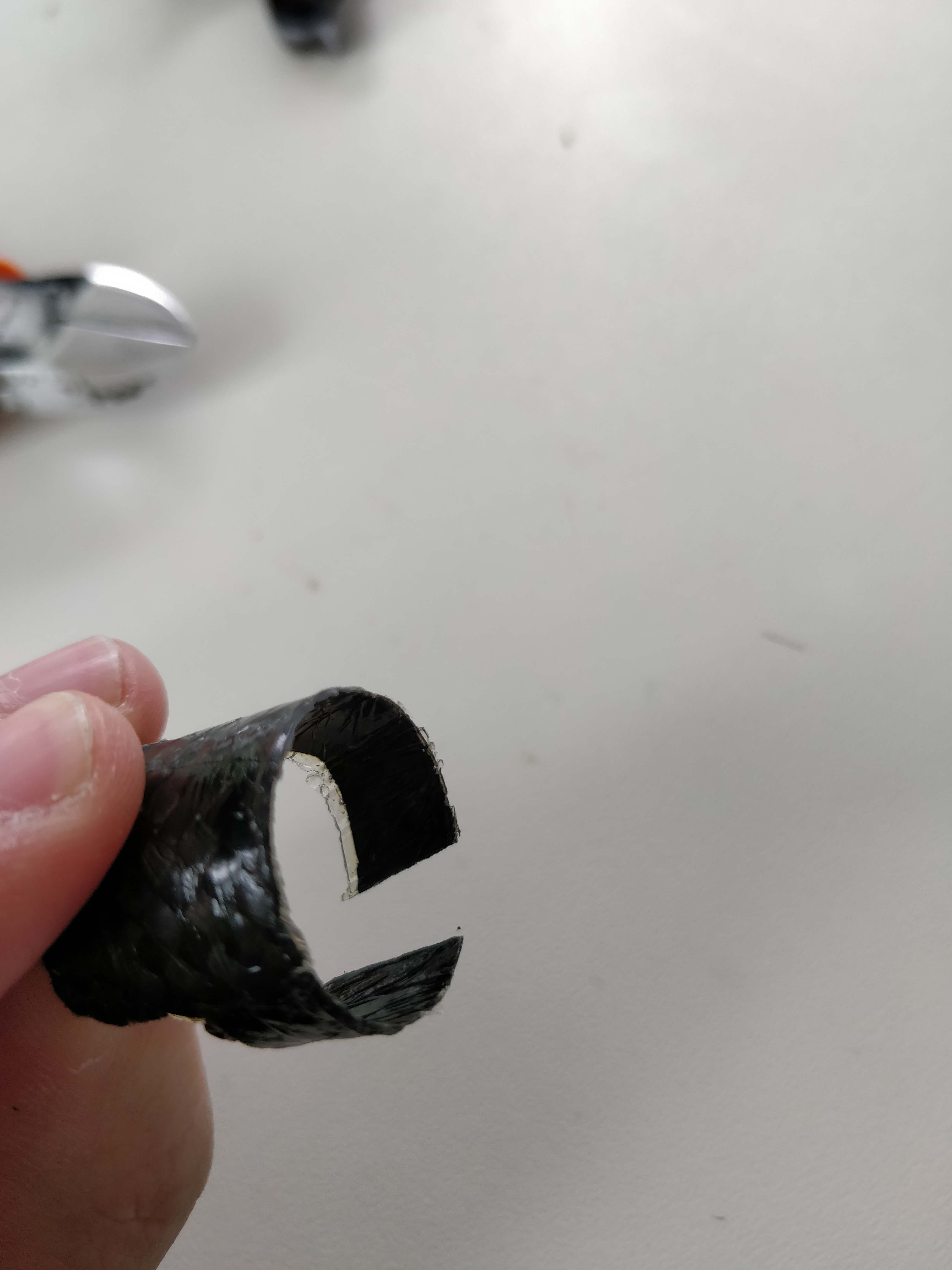
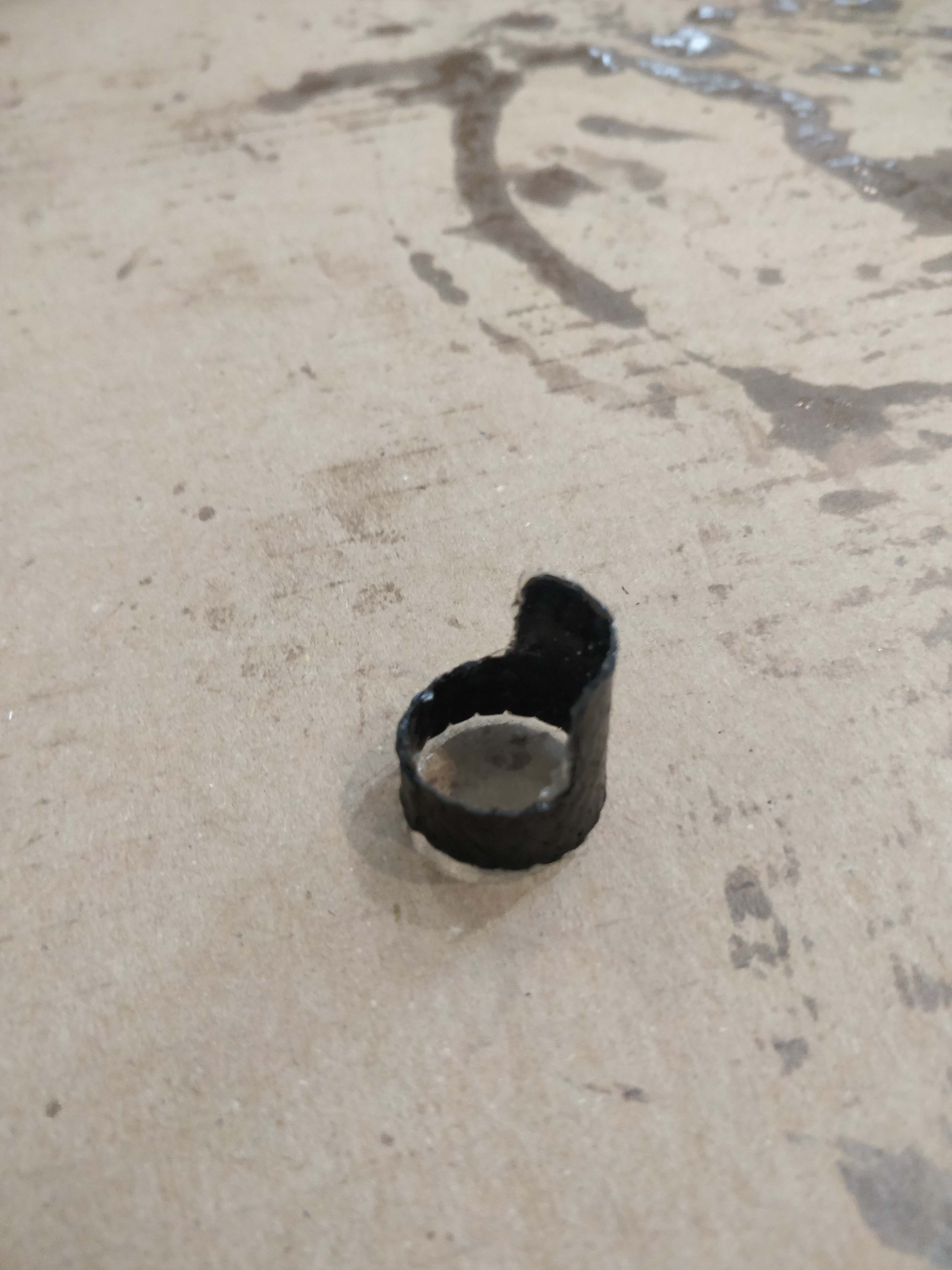
After that I jumped straight into Fusion to design the different kinds of rings, that would then be cut out in carbon fibre and shaped using a metal pole and of course epoxy resin. But that process is already documented in my wildcard week assignment. As you can see, some of them are a full ring, while others have a gap, this is so they fit snuggly over each and every finger independent of the user's finger's girth. The end result looked like this.
Then I turned my attention to the joints between the different rings. At first I wanted to 3d print solid hinges, but decided that flat springs made from flexible filament are the much more sensical decicion.
So I jumped right back into fusion and started iterating. My first designs were way too thick (2mm) so I could tell that they wouldn't be flexible enough.
I then made them be 1mm in thickness and was satisfied with the result, until I actually fastened them to a few of the rings and tried it out. They had to be able to expand which they were not, so I iterated one more time and came up with this:
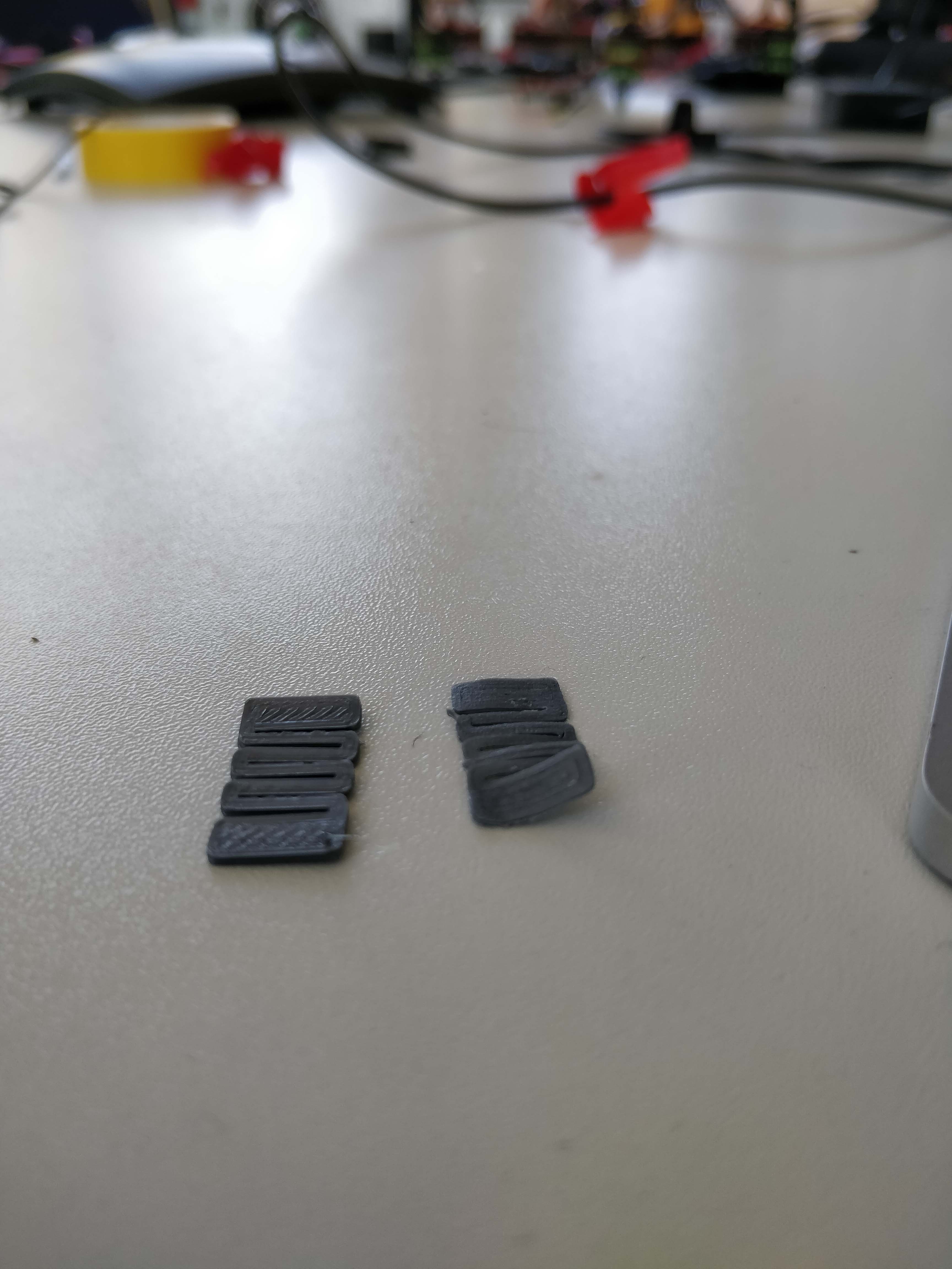
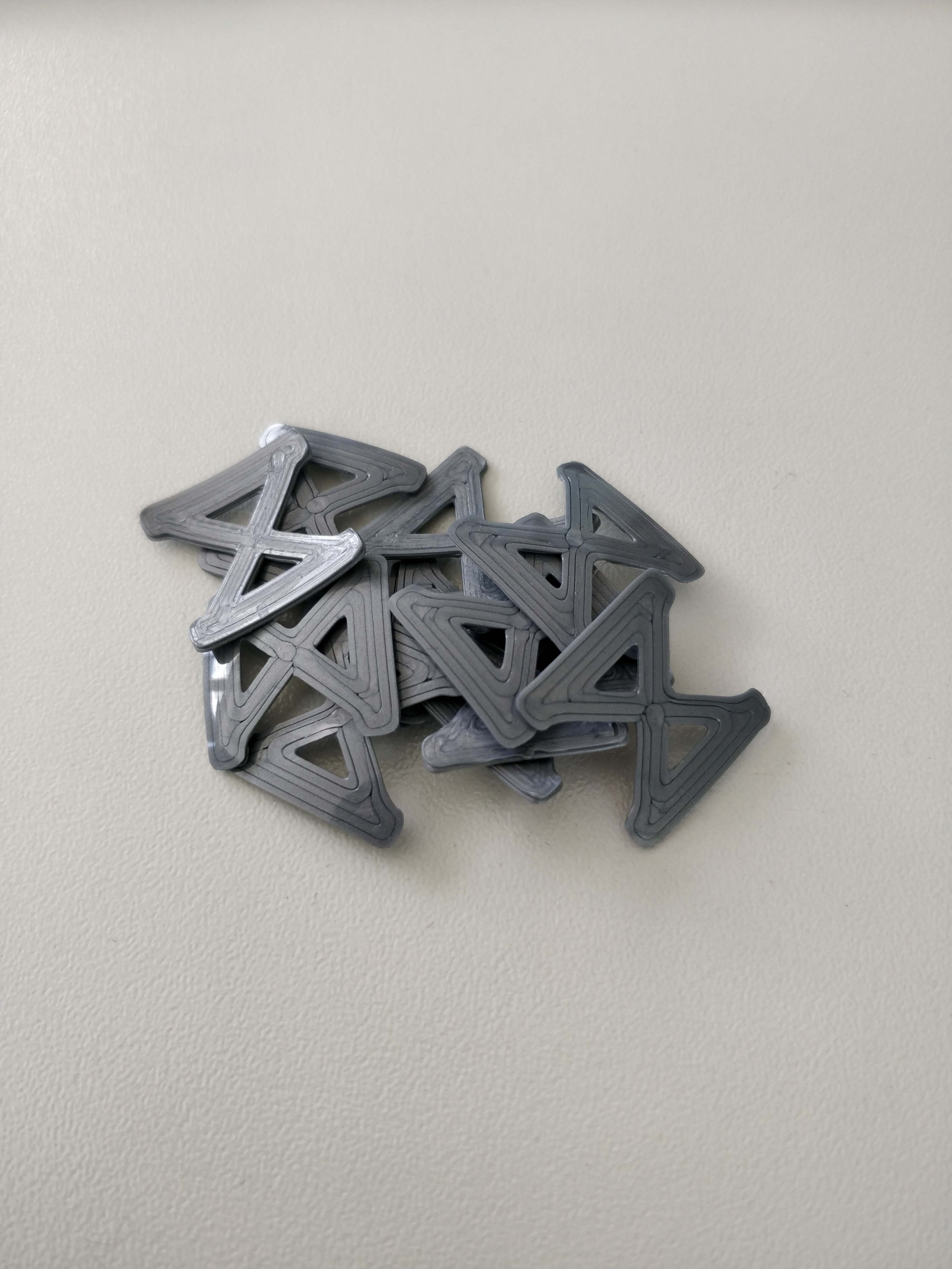
After trying out different thicknesses and finally settling on the 1mm ones, they worked like a charm and I could go on to the next part, which are the guides/anchors for the tendons.
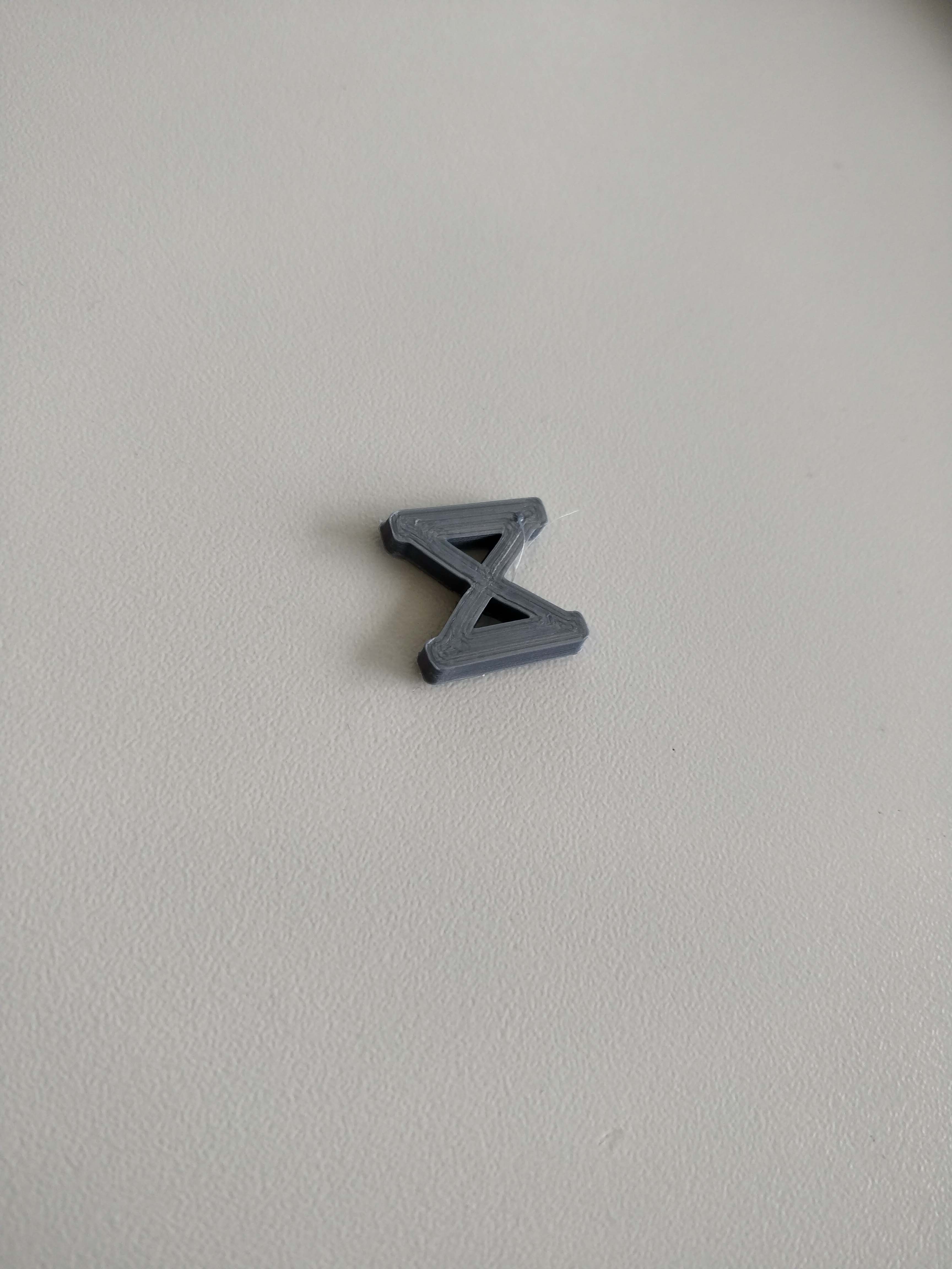
These are basically just small 3d-printed pieces with a hole for the tendon to go through, they were easy to design and printed beautifully. Their rounded bottom shape, is so that the would fit onto the joints properly and had the most amount of surface contact possible.
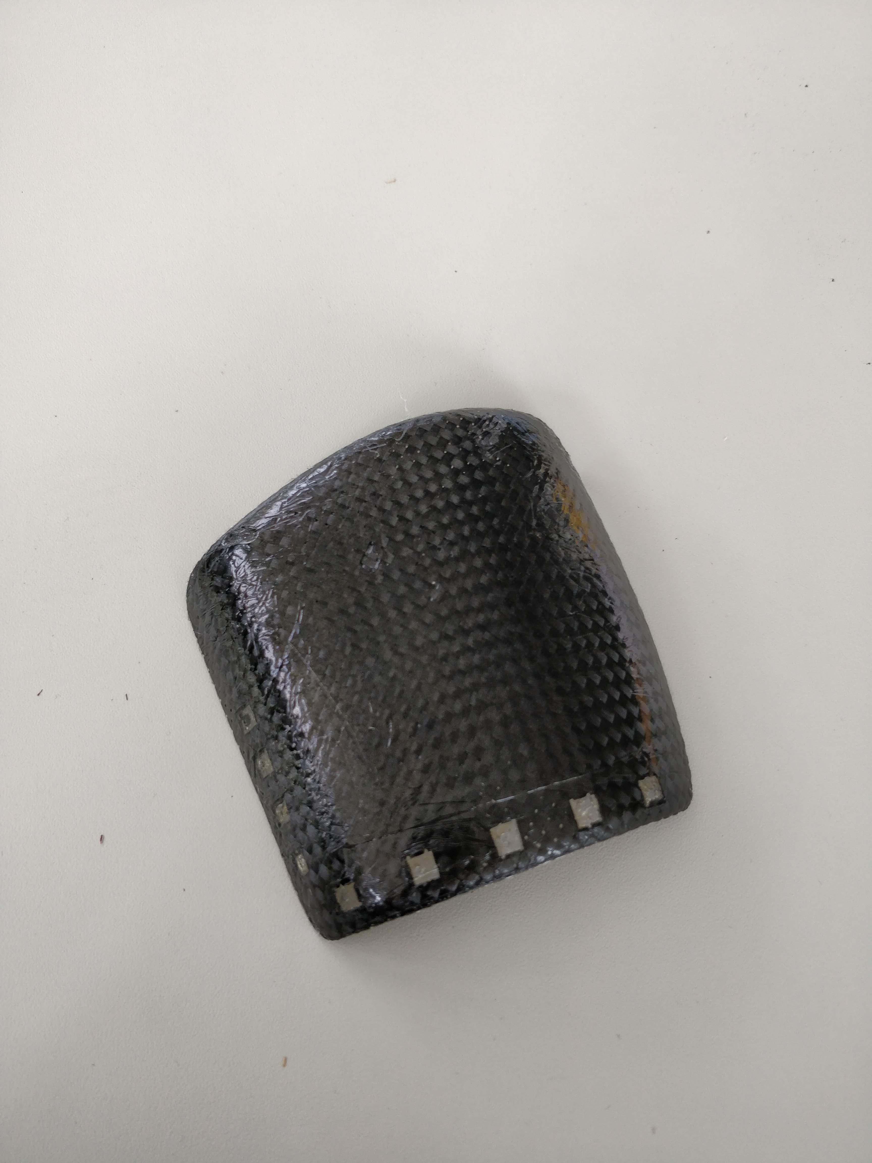
Next up was the big carbon piece that goes ontop ot the hand. The process is exactly the same as with the rings, allthough now I needed to cnc-machine a mold for the composite to sit on while it cured.
For that I took the model which I made before and imported it into fusion360, where I then extruded it and generated gcode for the cnc-machine.
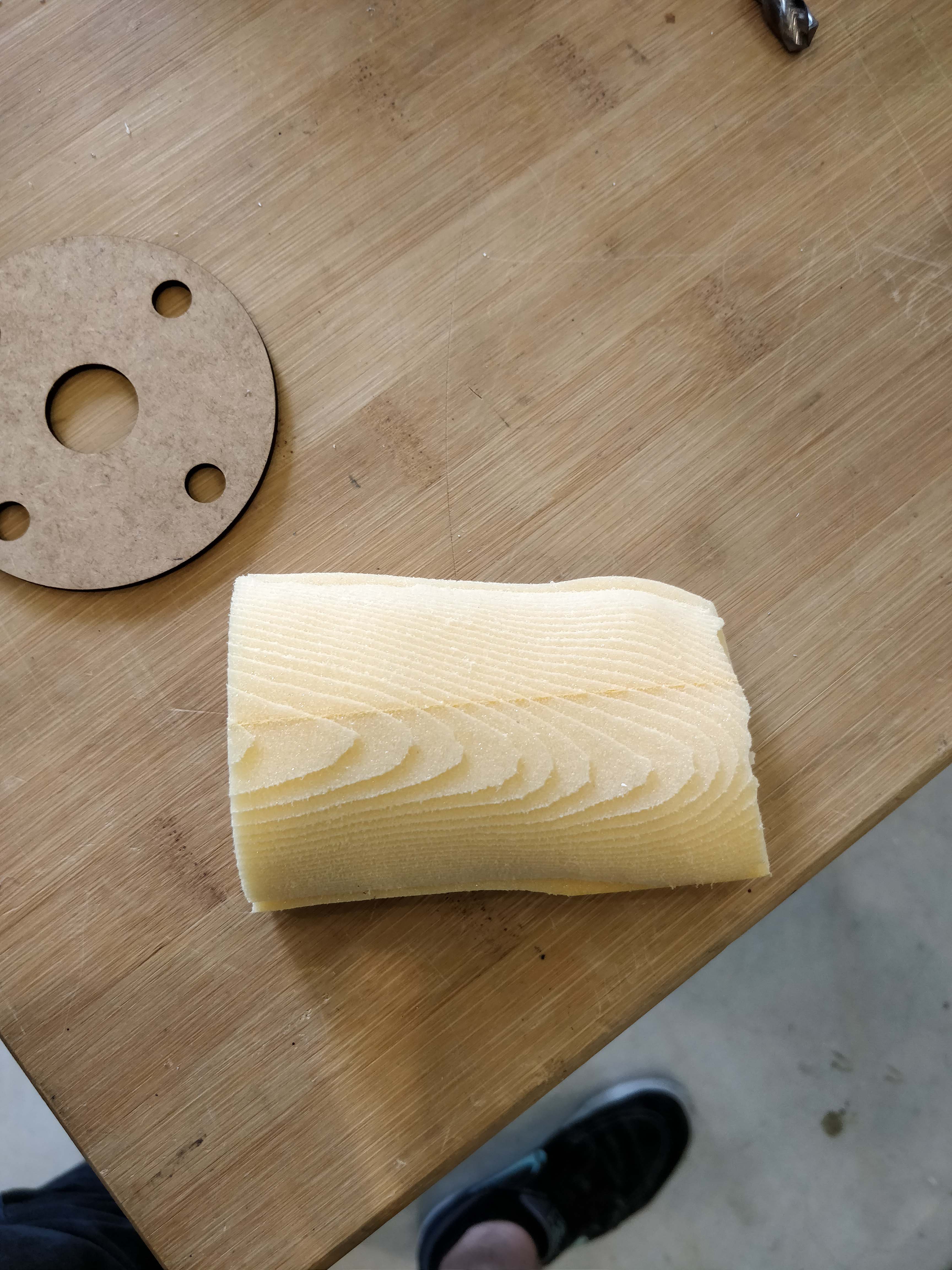
I then milled it in foam, which took about 20 minutes. And after another 20 minutes for the final cut it came out looking like this:
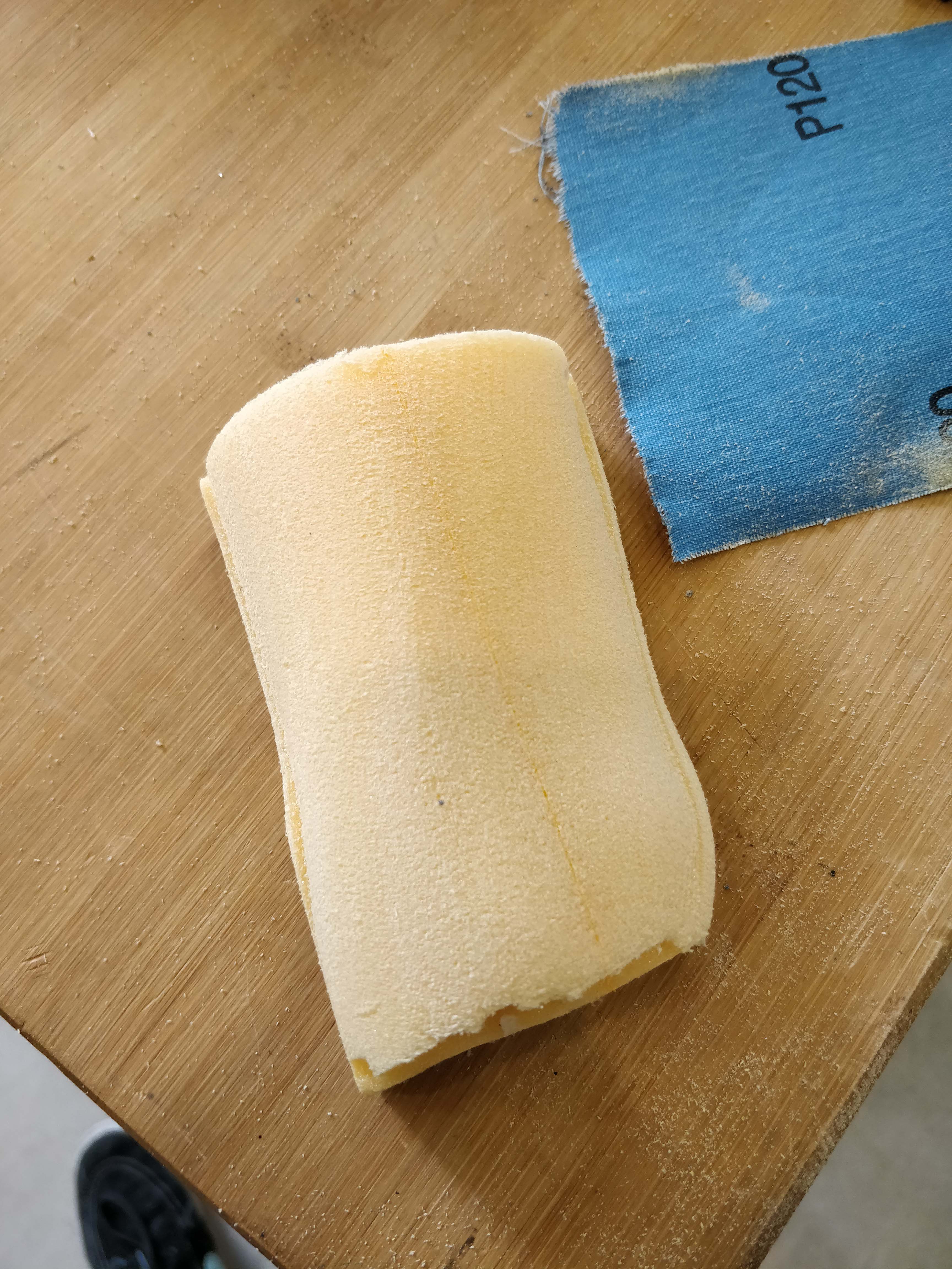
After that, I just had to clean it up and remove the wall that was left over by the mill.
Now the carbon could be lasercut and coated with epoxy.
It was then wrapped with ceran wrap, layed onto the mold and put in the vacuum former, where it cured over night.
After It was cured, I removed the leftover ceran wrap and was left with this:
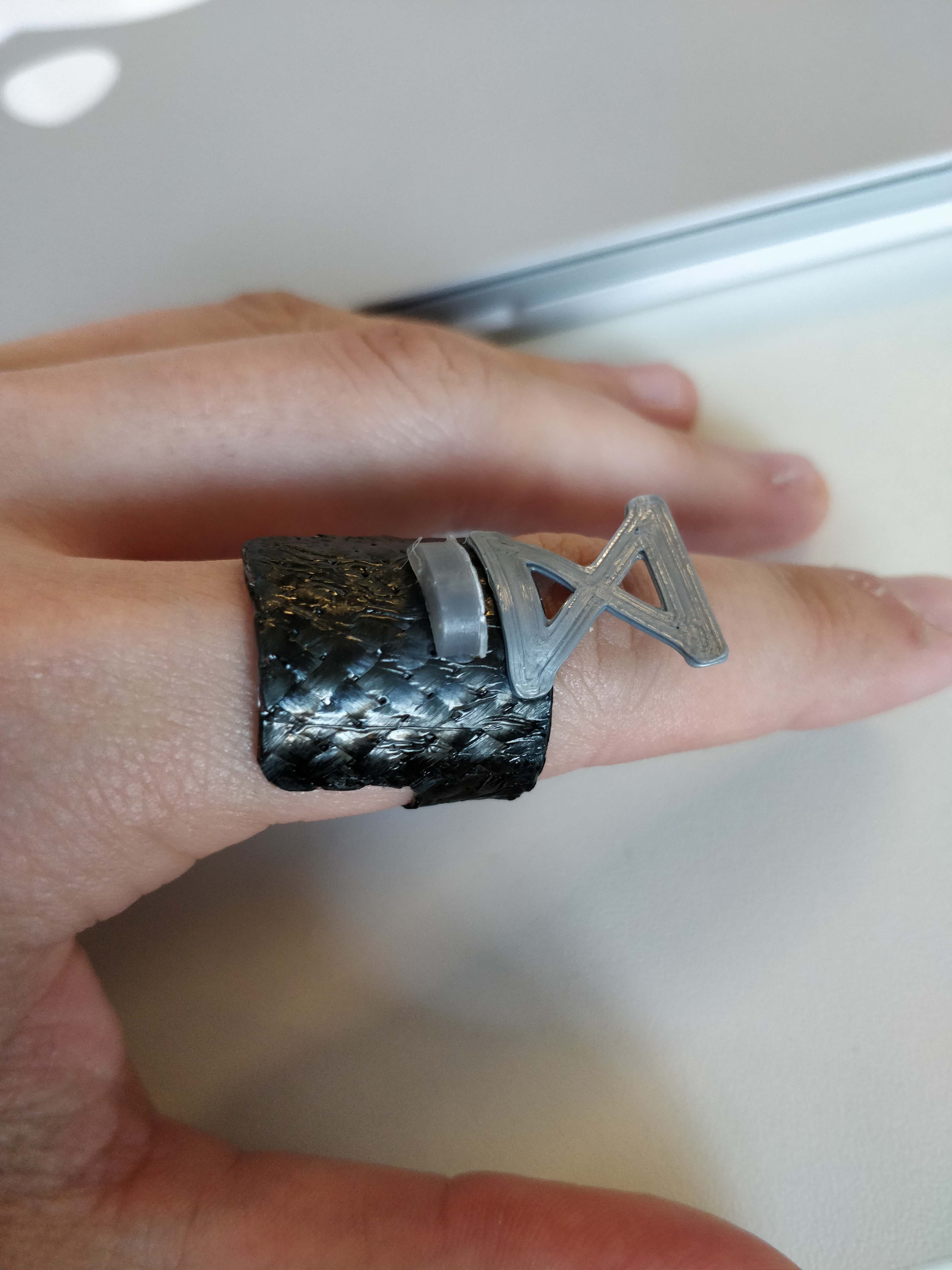
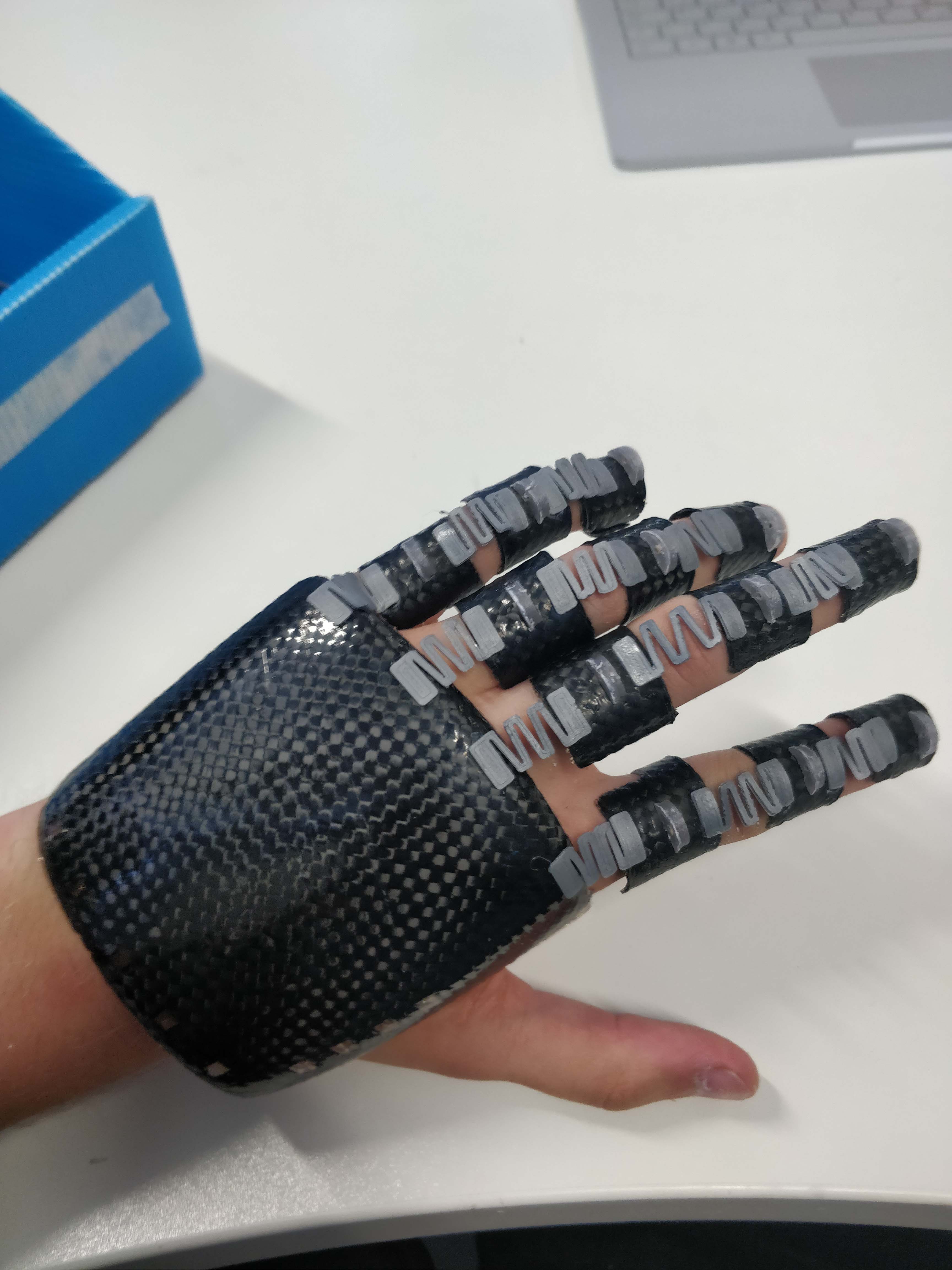
As a test, I then assembled all of the parts I made so far, which included the finger joints, their connection pieces made from flexible filament, the wire guides and the big piece for the top of the hand. All of the parts were fixed with ca-glue and another layer of epoxy, to lock them in place permanently.
The same process as for the top of the hand was then repeated for the part that sits on the forearm. The only difference was, that I 3d-scanned my own forearm, to make it as precise as possible. Instructions on how to 3d-scan objects can be found here
The only difference between the two is that I didn't do a finishing job, but rather lightly sanded the foam because of time reasons.
The final result looked like this:

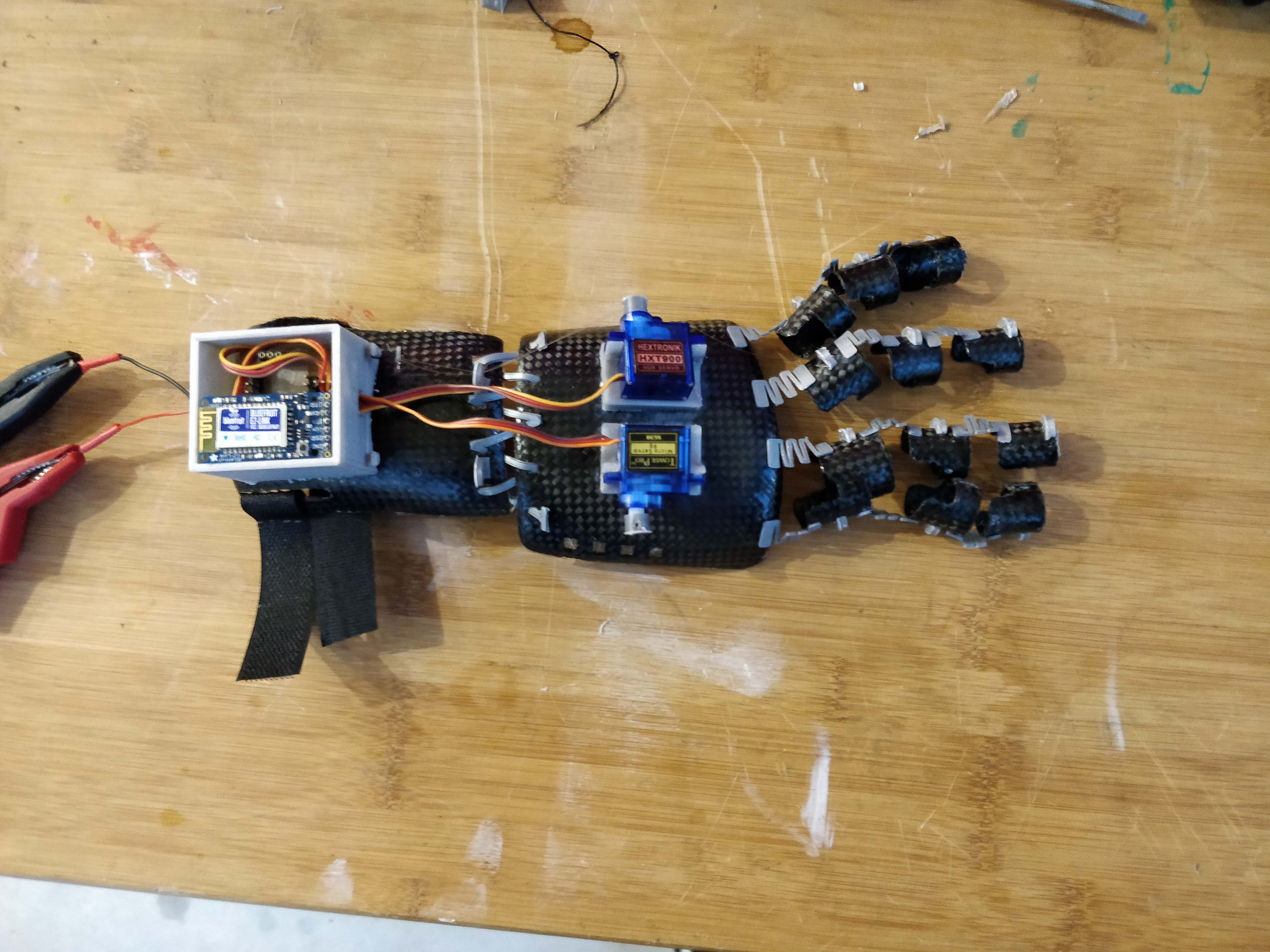
Once that was done, I designed two holders for the servo motors I was going to use. Their bottom surfaces are designed to perfectly fit onto the top of the hand, again to maximize the touching surface area.
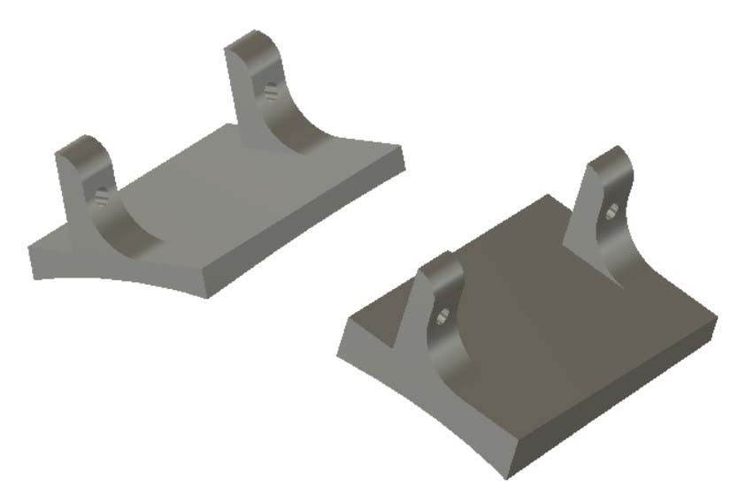
These holders were then 3d printed and glued onto the top of the hand in their respective places.
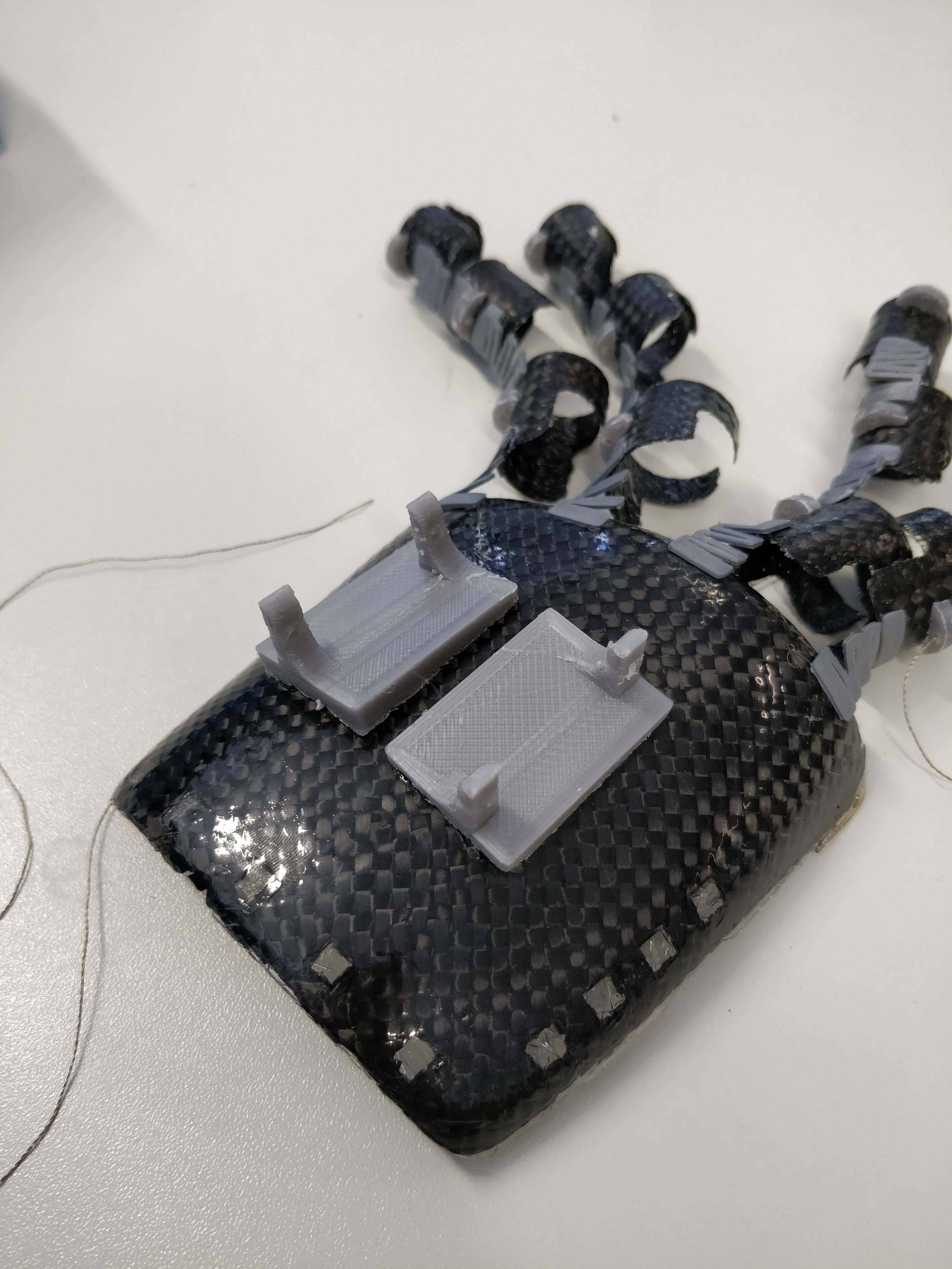
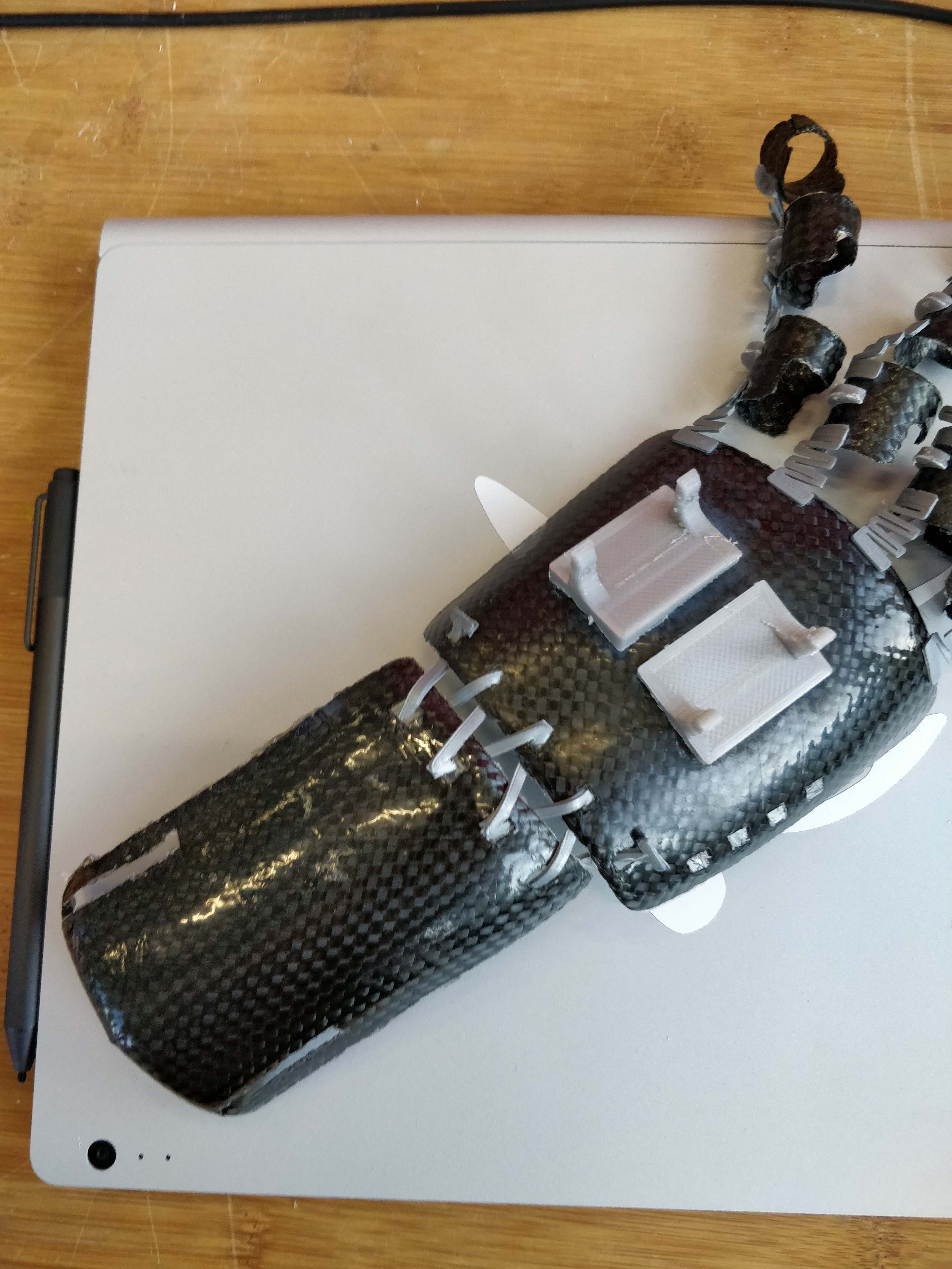
After that I designed a flexible piece that would be woven between those two parts.

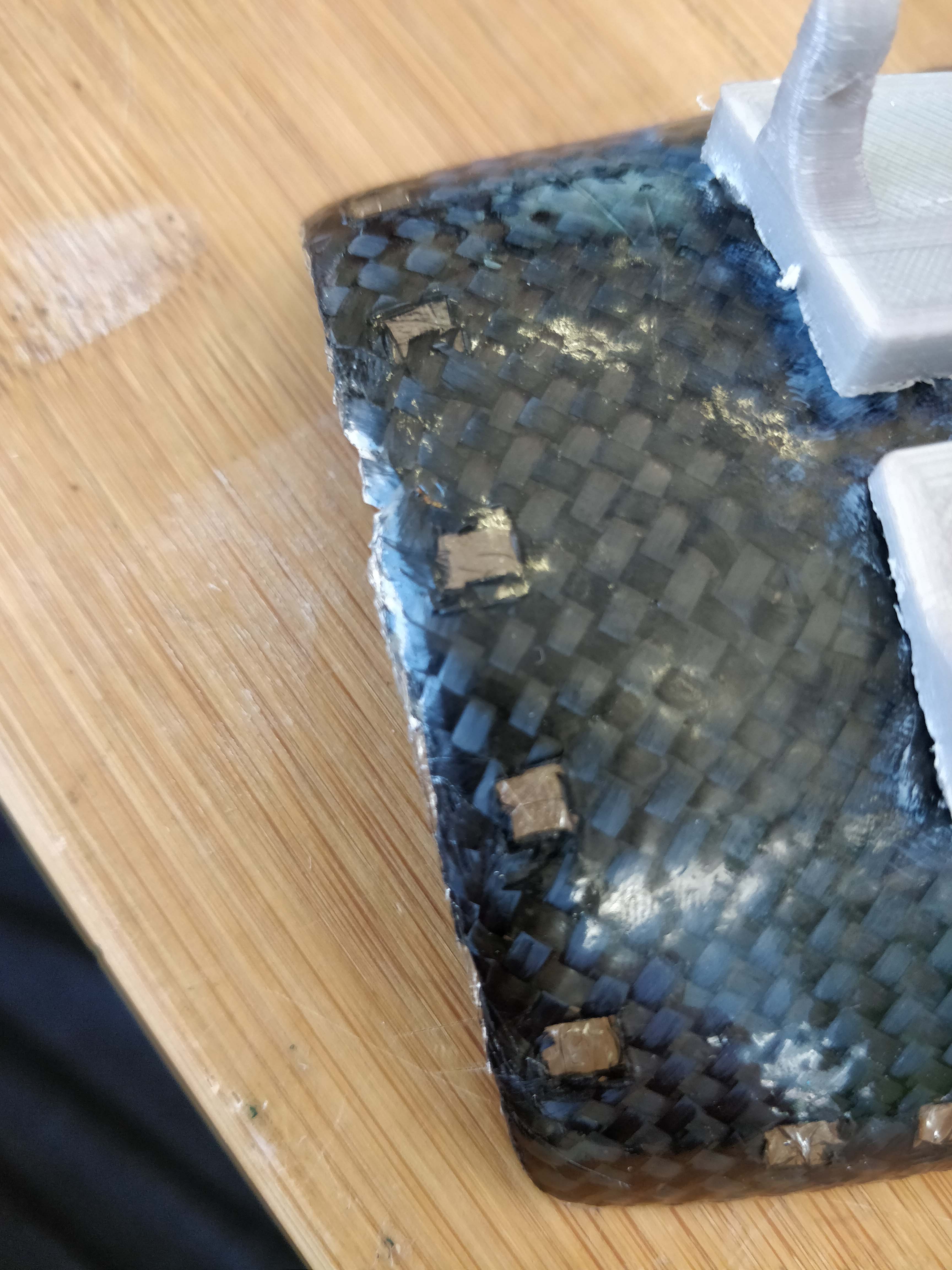
It worked on the first time, because now I had experiance with the proprties of the filament. The piece would be inserted into the lasercut squares in the top hand part and the forearm.
The assembled result looks like this:
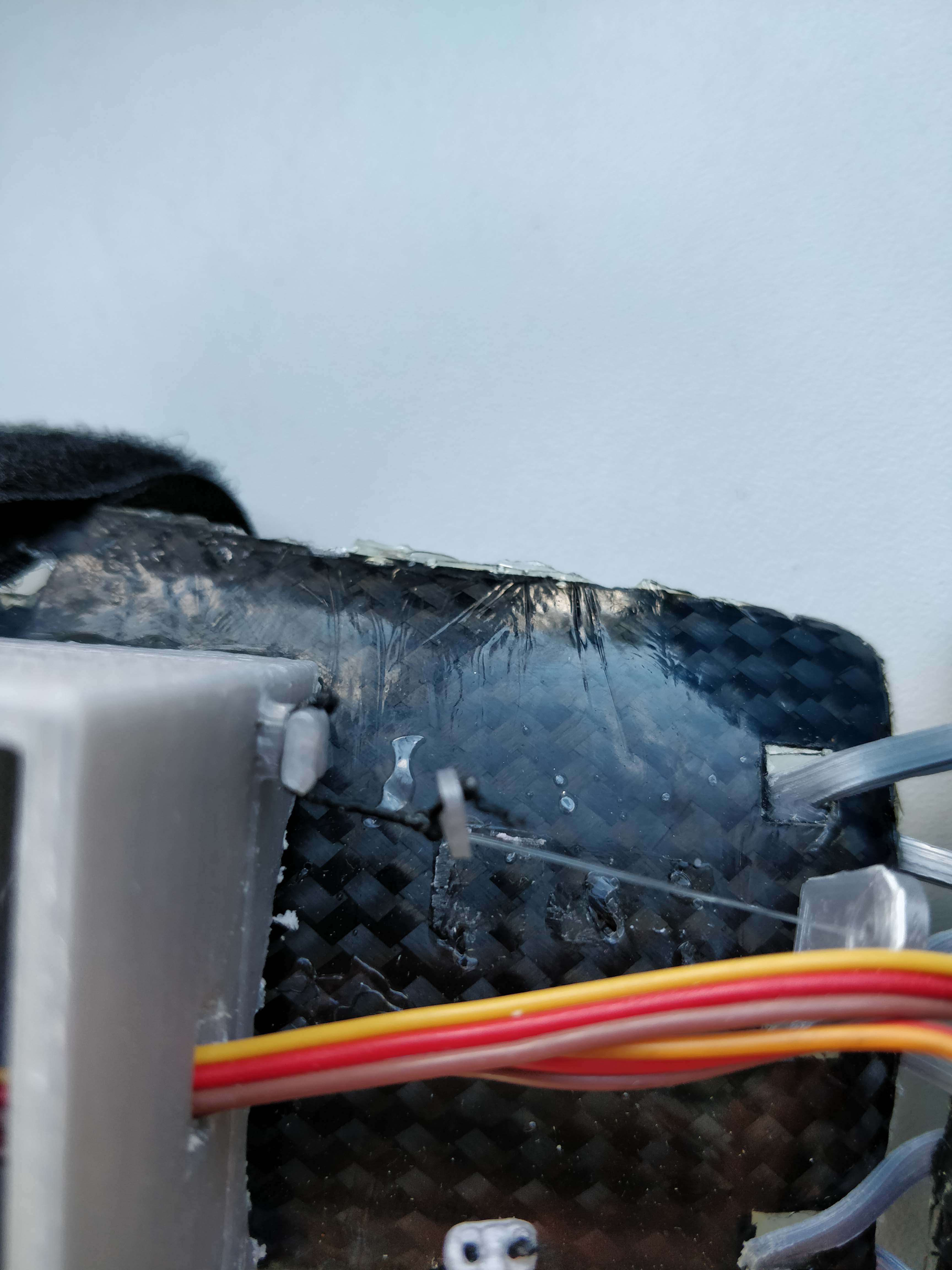
And now the only thing left to do was a box for the electronics, which was also swiftly printed and attached to the arm piece.
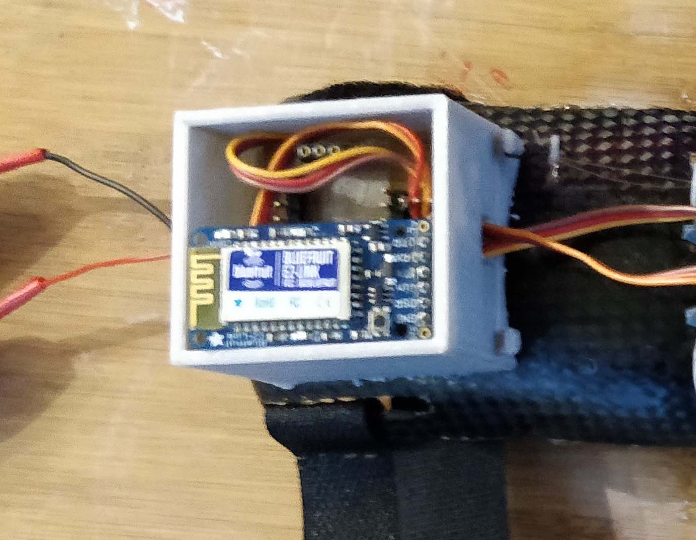
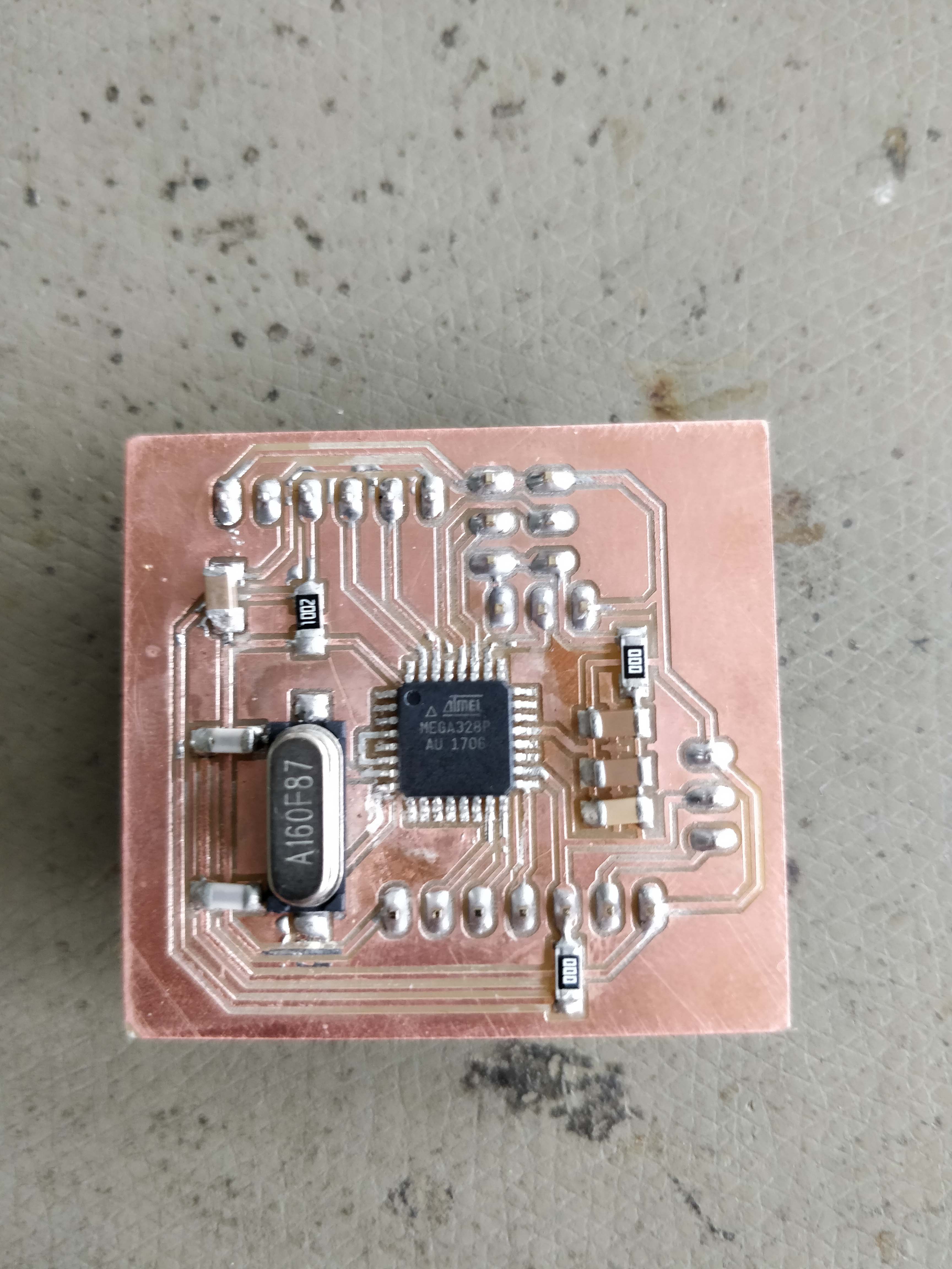
The electronics were already there at this point, because I made the board for the networking assignment
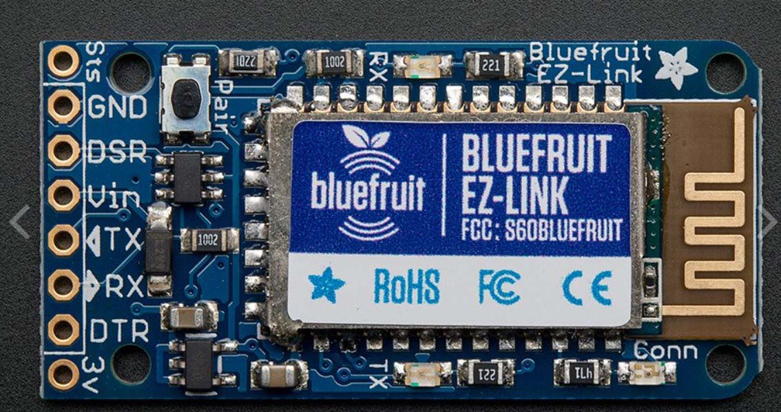
As stated in the networking assignment as well, I used the adafruit ez-link to communicate wirelessly with my board.
So I just had to attach the servos to it and program it. This is the code, that I put on there:
As you can see, it is not very complicated, it just turns the servo whenever it recieves the signal over bluetooth serial communication.
The only thing left to do now, was to insert the fishing wire into the premade holders and attach it to flexible string via a little plastic cuppler
to make it have tension all the time.
And That's it! this is my final project! all the files can be downloaded at the bottom of this page.
Download everything
The plan is to restrict the user's finger's movement whenever he grabs something in vr, so it feels like he is grabbing it in real life as well.
This is an illustration of my first idea, as it is also in the "principles and practices"- assignment.
At first work on this project only consisted of research on how to actually restrict any movement.
The first idea was to do something with pneumatics. I found out, that if you have a flexible container with some kind of powdery substance inside of it and pull a vacuum on it, it turns solid. Therefore the idea was to put such containers on each and every joint of the fingers and be able to control them individually.
however this idea came to an abrubt halt, when we tried it and noticed, that it pretty much doesn't provide any feedback whatsoever.
Unfortunately the pictures and video of that happening went missing, so here is where I got the idea originally.
The next idea came from my laptop, it's display can detach with a muscle wire mechanism so I researched further into the so called "shape memory alloys" and came across nitinol. Which is supposed to contract when current is applied to it and expand to it's original length when it cools back down again.
I thought that this was perfect for my application, since I could just have a piece of it at each joint and contract/expand it however I want.
But before I went and designed something, I decided to first experiment with it for a while. Which turned out to be a huge timesaver, because as it turns out The nitinol gets REALLY HOT when applying the current needed for it to contract at the rate I wanted it to. And also it doesn't go back to it's original length without external force, which could have been provided by the user's hand, but way too much force was needed so that plan had to go as well.
So at that point I turned back to my original idea, which is just a machanism using fishingwire tedons and servos to lock them in place at an arbitrary point. As that seemed plausible and I was sure it would simply work, I had gone ahead and started designing the exo-skeleton that I want to mount everything to.
As you can see here, this is the first design I made in Blender (more about blender) to get a better Idea of wether or not it was going to work.
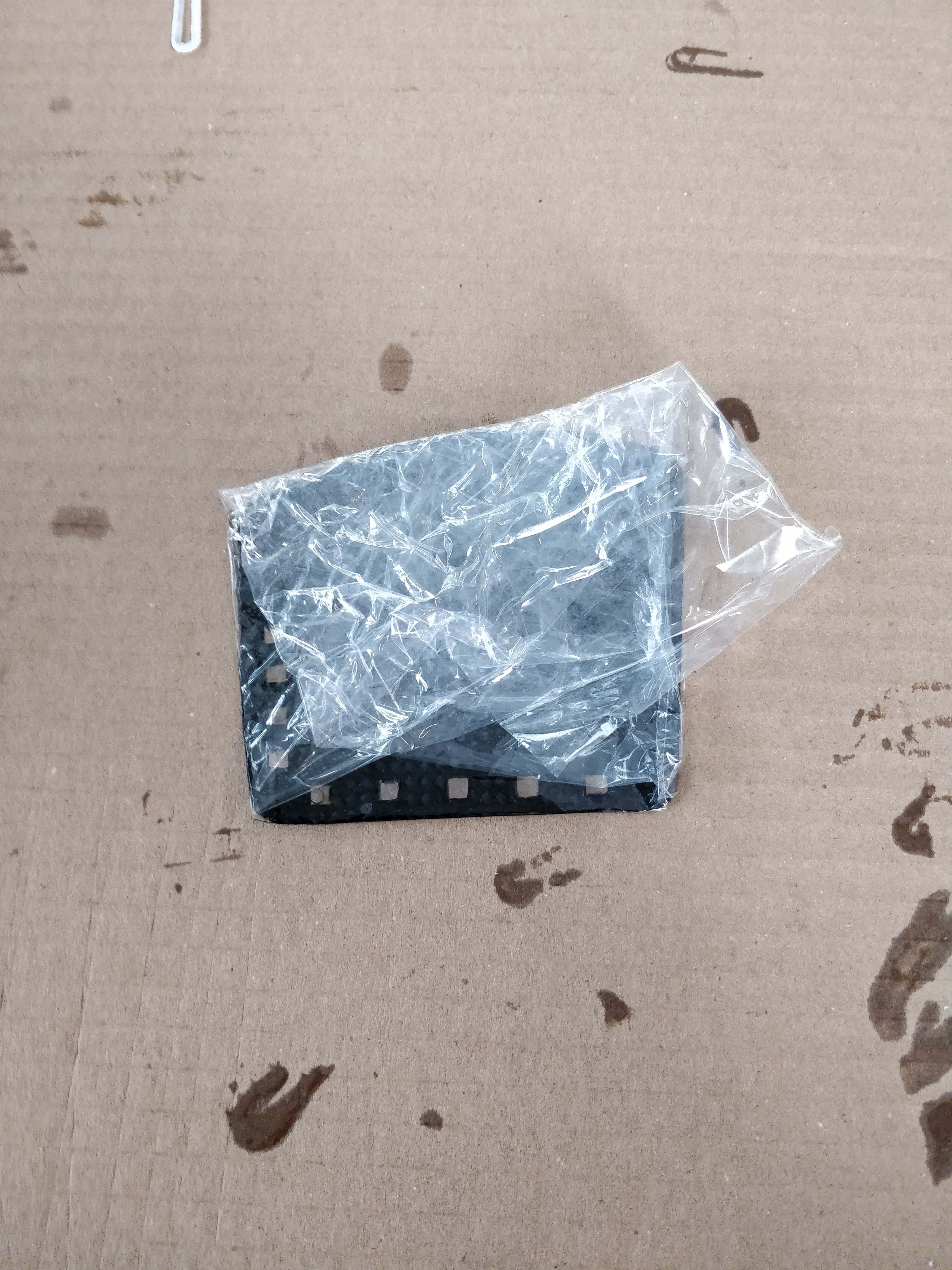
After that I jumped straight into Fusion to design the different kinds of rings, that would then be cut out in carbon fibre and shaped using a metal pole and of course epoxy resin. But that process is already documented in my wildcard week assignment. As you can see, some of them are a full ring, while others have a gap, this is so they fit snuggly over each and every finger independent of the user's finger's girth. The end result looked like this.
Then I turned my attention to the joints between the different rings. At first I wanted to 3d print solid hinges, but decided that flat springs made from flexible filament are the much more sensical decicion.
So I jumped right back into fusion and started iterating. My first designs were way too thick (2mm) so I could tell that they wouldn't be flexible enough.
I then made them be 1mm in thickness and was satisfied with the result, until I actually fastened them to a few of the rings and tried it out. They had to be able to expand which they were not, so I iterated one more time and came up with this:
After trying out different thicknesses and finally settling on the 1mm ones, they worked like a charm and I could go on to the next part, which are the guides/anchors for the tendons.
These are basically just small 3d-printed pieces with a hole for the tendon to go through, they were easy to design and printed beautifully. Their rounded bottom shape, is so that the would fit onto the joints properly and had the most amount of surface contact possible.
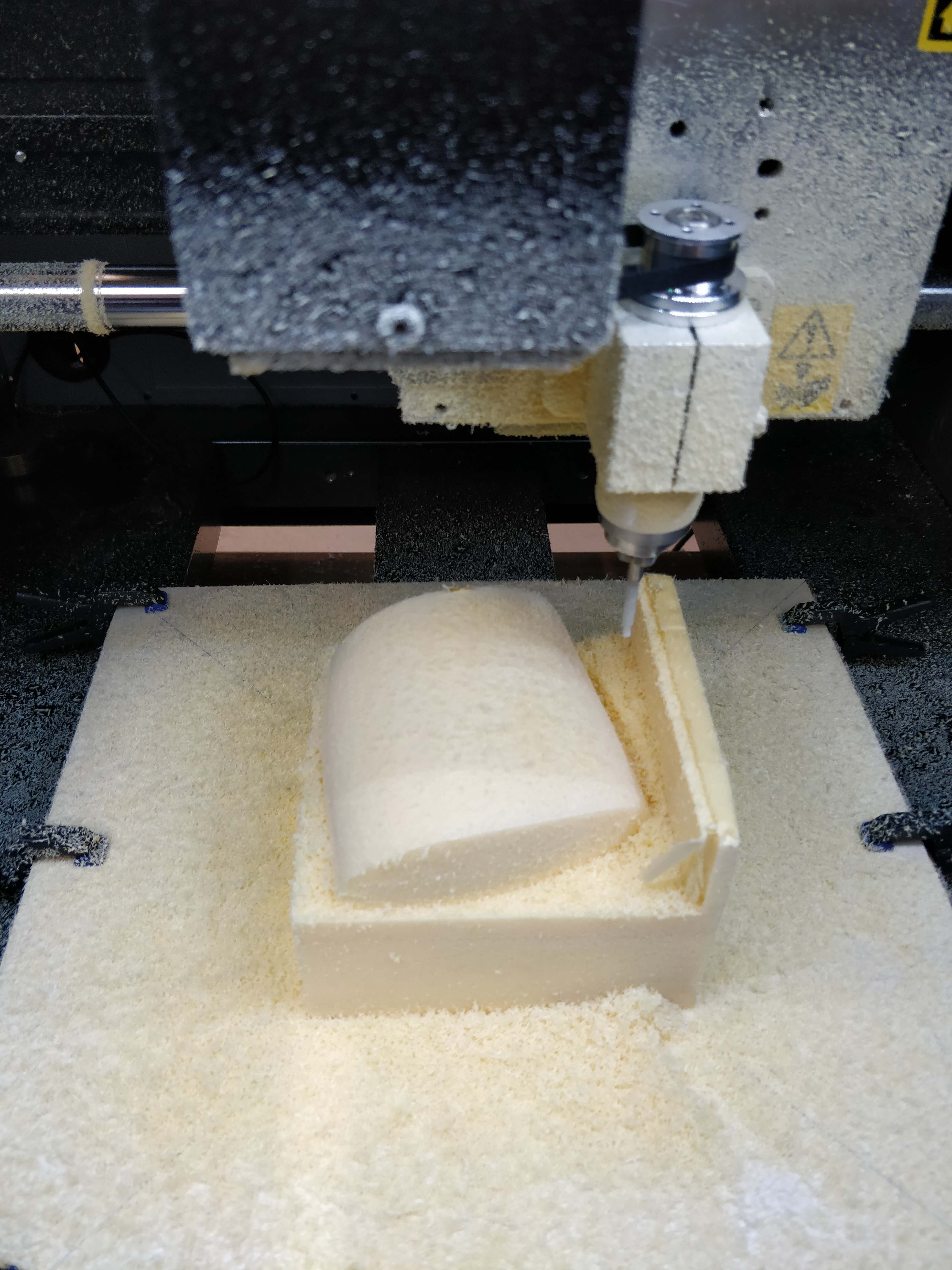
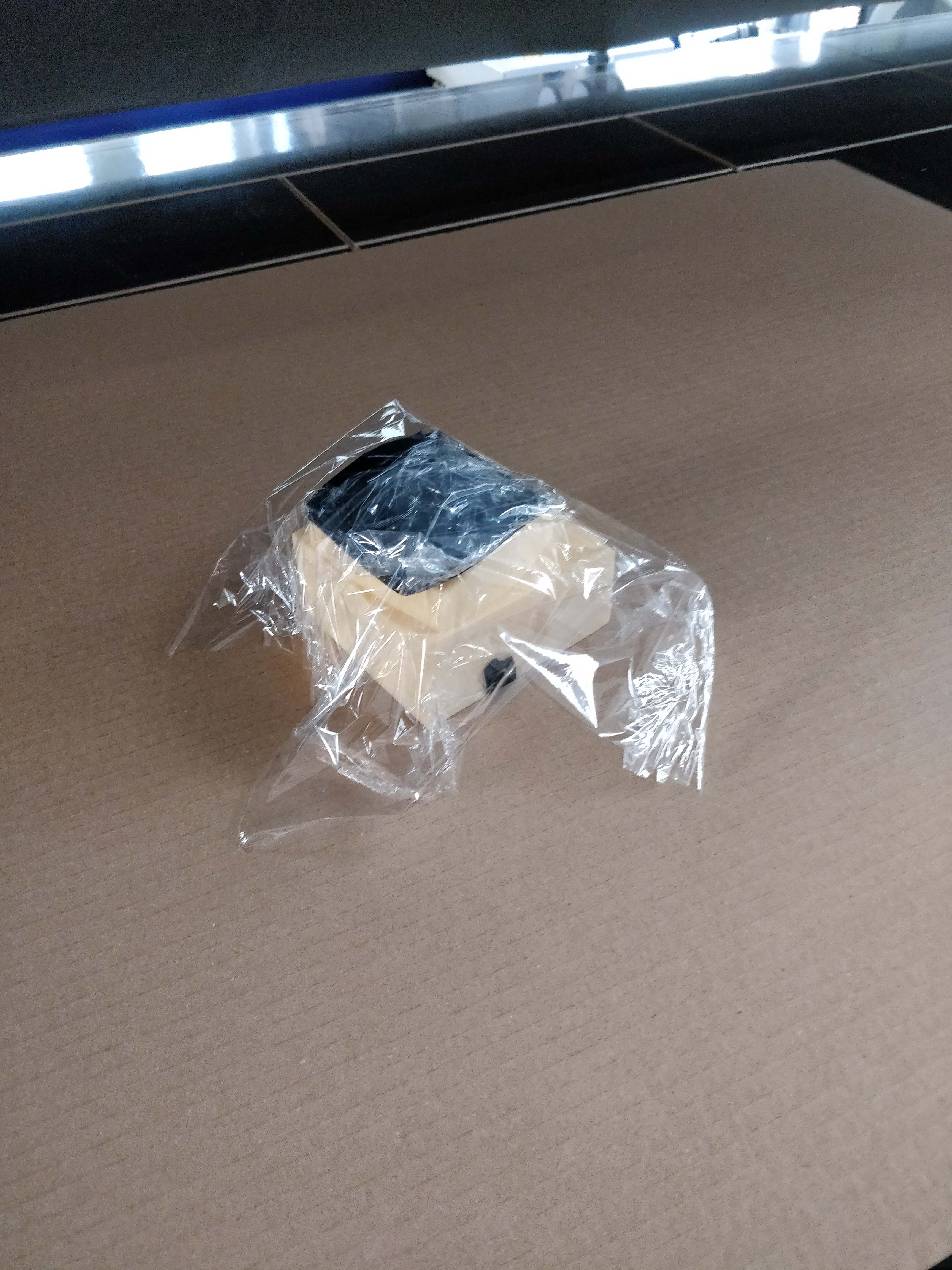
Next up was the big carbon piece that goes ontop ot the hand. The process is exactly the same as with the rings, allthough now I needed to cnc-machine a mold for the composite to sit on while it cured.
For that I took the model which I made before and imported it into fusion360, where I then extruded it and generated gcode for the cnc-machine.
I then milled it in foam, which took about 20 minutes. And after another 20 minutes for the final cut it came out looking like this:
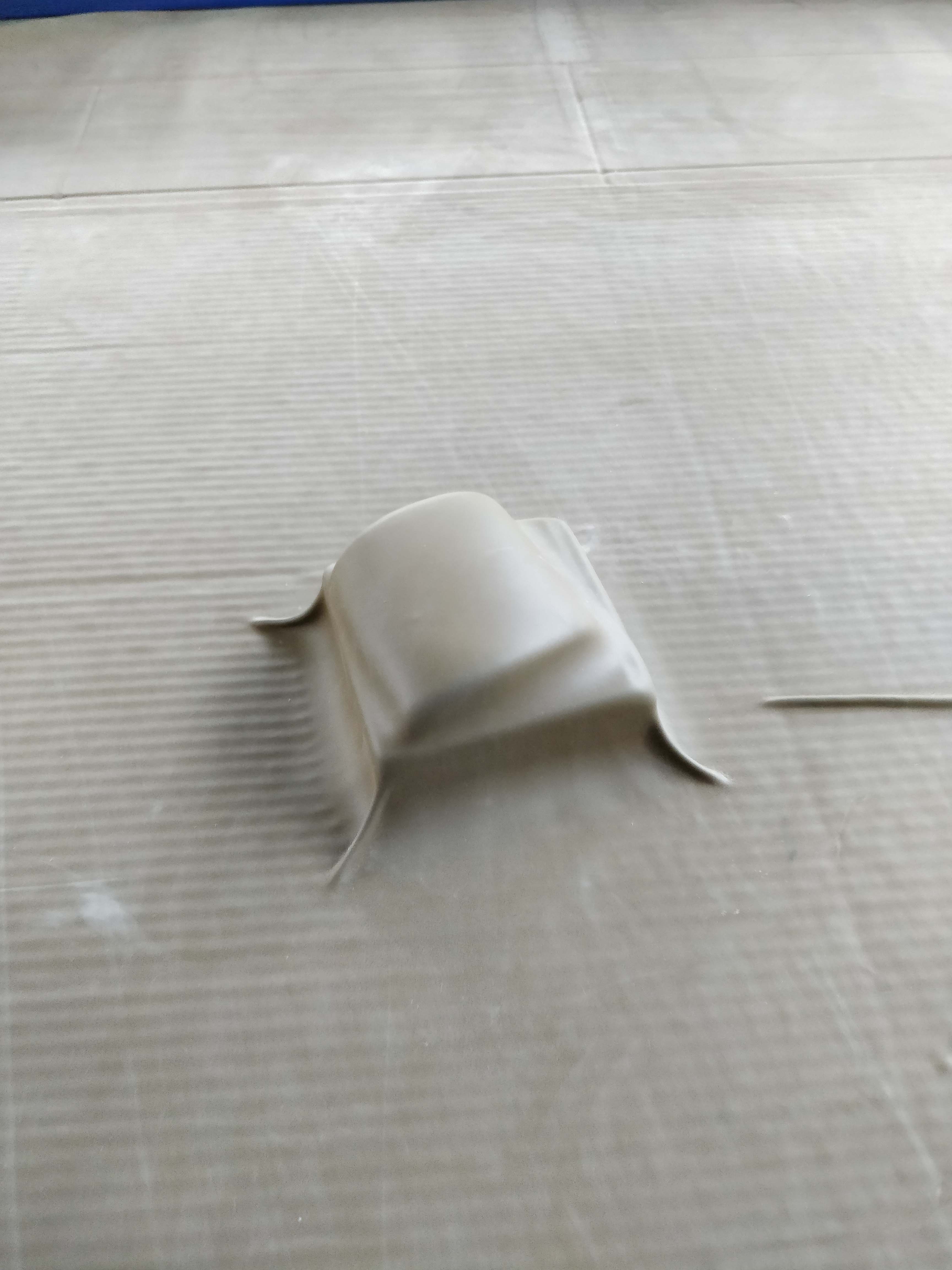
After that, I just had to clean it up and remove the wall that was left over by the mill.
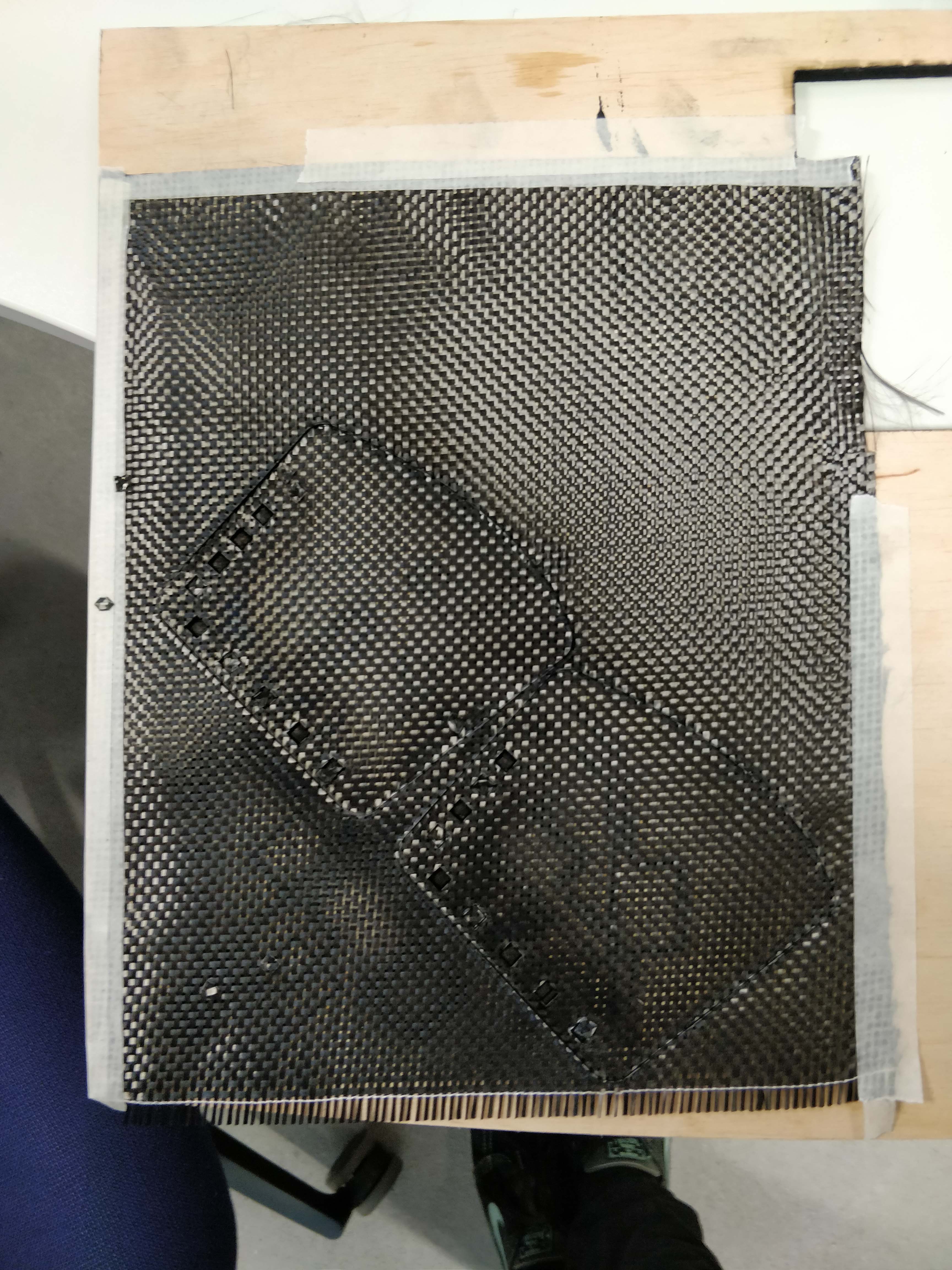
Now the carbon could be lasercut and coated with epoxy.
It was then wrapped with ceran wrap, layed onto the mold and put in the vacuum former, where it cured over night.
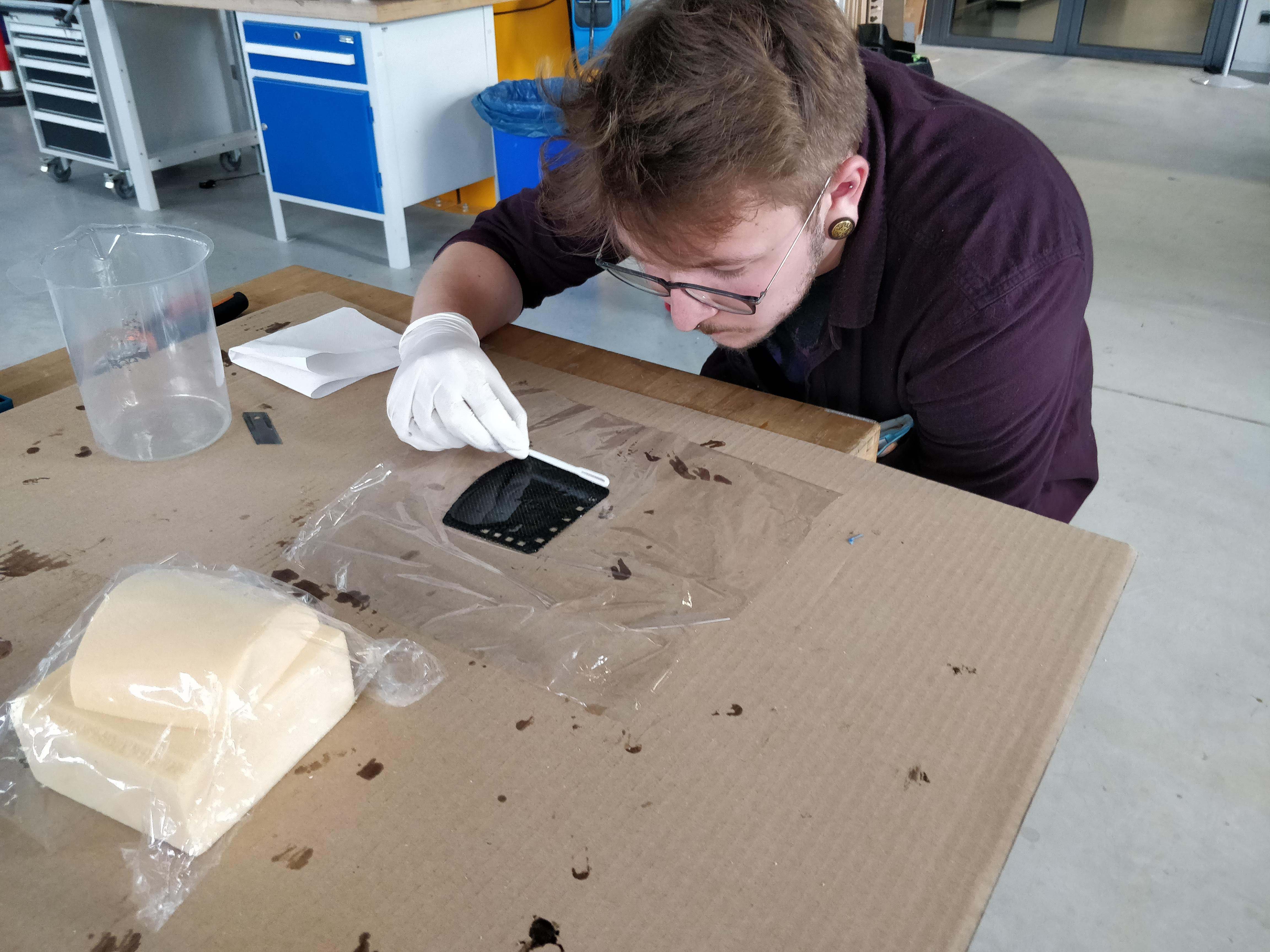
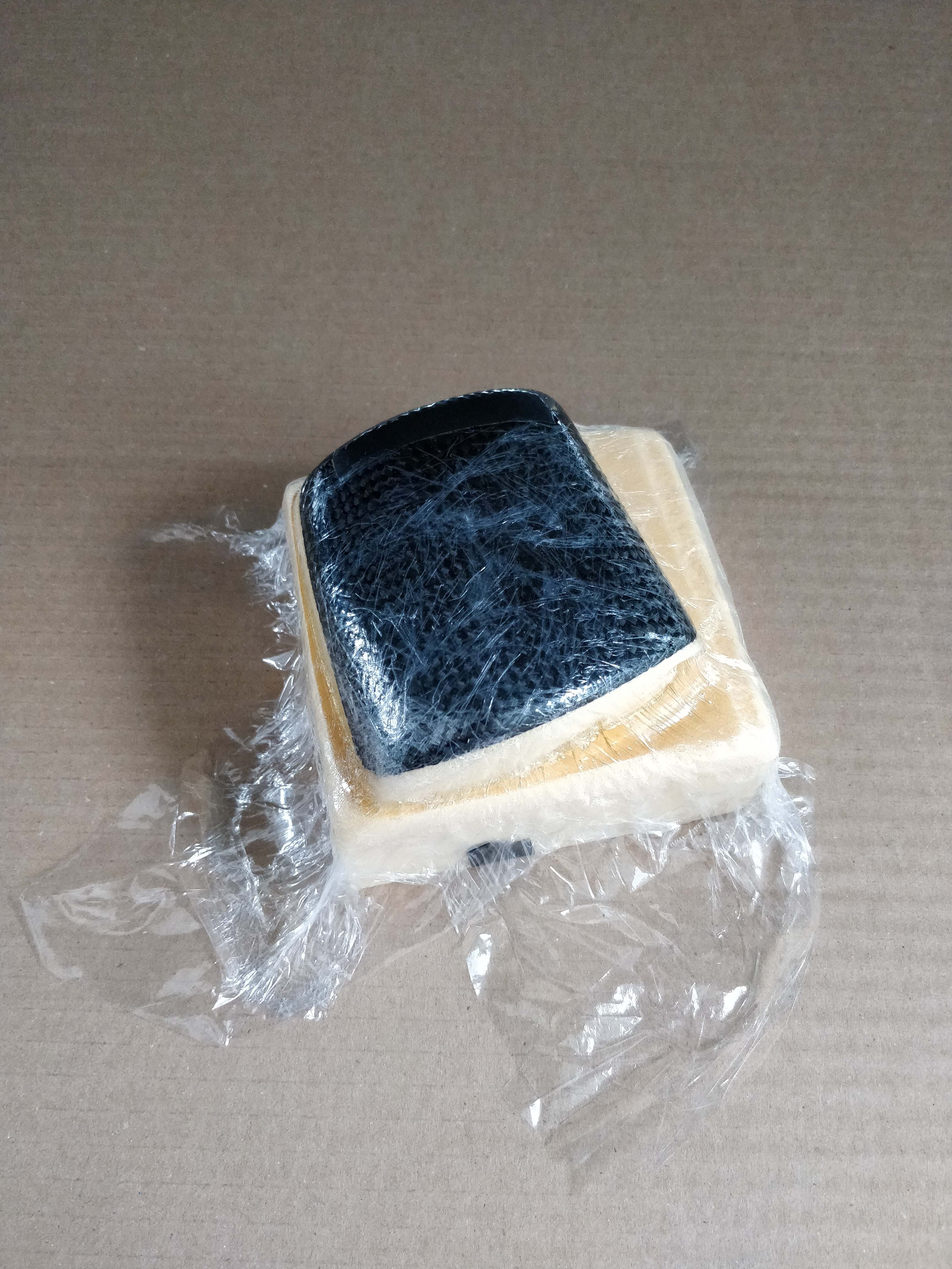
After It was cured, I removed the leftover ceran wrap and was left with this:
As a test, I then assembled all of the parts I made so far, which included the finger joints, their connection pieces made from flexible filament, the wire guides and the big piece for the top of the hand. All of the parts were fixed with ca-glue and another layer of epoxy, to lock them in place permanently.
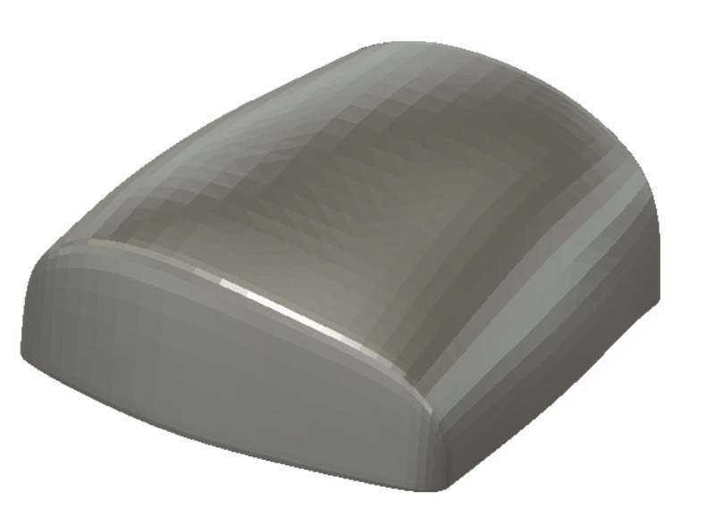
The same process as for the top of the hand was then repeated for the part that sits on the forearm. The only difference was, that I 3d-scanned my own forearm, to make it as precise as possible. Instructions on how to 3d-scan objects can be found here
The only difference between the two is that I didn't do a finishing job, but rather lightly sanded the foam because of time reasons.
The final result looked like this:
Once that was done, I designed two holders for the servo motors I was going to use. Their bottom surfaces are designed to perfectly fit onto the top of the hand, again to maximize the touching surface area.
These holders were then 3d printed and glued onto the top of the hand in their respective places.
After that I designed a flexible piece that would be woven between those two parts.
It worked on the first time, because now I had experiance with the proprties of the filament. The piece would be inserted into the lasercut squares in the top hand part and the forearm.
The assembled result looks like this:
And now the only thing left to do was a box for the electronics, which was also swiftly printed and attached to the arm piece.
The electronics were already there at this point, because I made the board for the networking assignment
As stated in the networking assignment as well, I used the adafruit ez-link to communicate wirelessly with my board.
So I just had to attach the servos to it and program it. This is the code, that I put on there:
                #include
Servo servoLeft;
Servo servoRight;
int pos1 = 0;
int pos2 = 0
String incomingByte = "";
void setup() {
  // put your setup code here, to run once:
  Serial.begin(9600);
  //pinMode(A5, OUTPUT);
servoLeft.attach(A5);
servoLeft.attach(A6);
}

void loop() {
  // put your main code here, to run repeatedly:
  if (Serial.available() > 0) {
                // read the incoming byte:
                incomingByte = Serial.readString();
                if(incomingByte.indexOf("open1") > -1){
                  for (pos1 = 0; pos1 <= 180; pos1 += 1) { // goes from 0 degrees to 180 degrees
                 // in steps of 1 degree
                 servoLeft.write(pos1);              // tell servo to go to position in variable 'pos'
                 delay(1);                       // waits 15ms for the servo to reach the position
                 }
                }else if(incomingByte.indexOf("close1") > -1){
                   for (pos1 = 180; pos1 >= 0; pos1 -= 1) { // goes from 180 degrees to 0 degrees
                    servoLeft.write(pos1);              // tell servo to go to position in variable 'pos'
                    delay(1);                       // waits 15ms for the servo to reach the position
                   }
                }else if(incomingByte.indexOf("open2") > -1){
                  for (pos2 = 0; pos2 <= 180; pos2 += 1) { // goes from 0 degrees to 180 degrees
                 // in steps of 1 degree
                 servoRight.write(pos2);              // tell servo to go to position in variable 'pos'
                 delay(1);                       // waits 15ms for the servo to reach the position
                 }
                }else if(incomingByte.indexOf("close2") > -1){
                   for (pos2 = 180; pos2 >= 0; pos2 -= 1) { // goes from 180 degrees to 0 degrees
                    servoRight.write(pos2);              // tell servo to go to position in variable 'pos'
                    delay(1);                       // waits 15ms for the servo to reach the position
                   }
                }
        }
}
As you can see, it is not very complicated, it just turns the servo whenever it recieves the signal over bluetooth serial communication.
The only thing left to do now, was to insert the fishing wire into the premade holders and attach it to flexible string via a little plastic cuppler
to make it have tension all the time.
And That's it! this is my final project! all the files can be downloaded at the bottom of this page.
Download everything