Computer controlled cutting
This week's individual assignment consisted of two parts. First (and very easy) cut something using the vinyl cutter, in my case that's the obligatory Laptop sticker. And second create a parametric "press fit kit"-design and lasercut it.
Vinyl cutting
The Vinyl cutter is a very easy device to operate, it basically works like a printer, once you have the software (silhouette studio) installed.
Here is what I did:
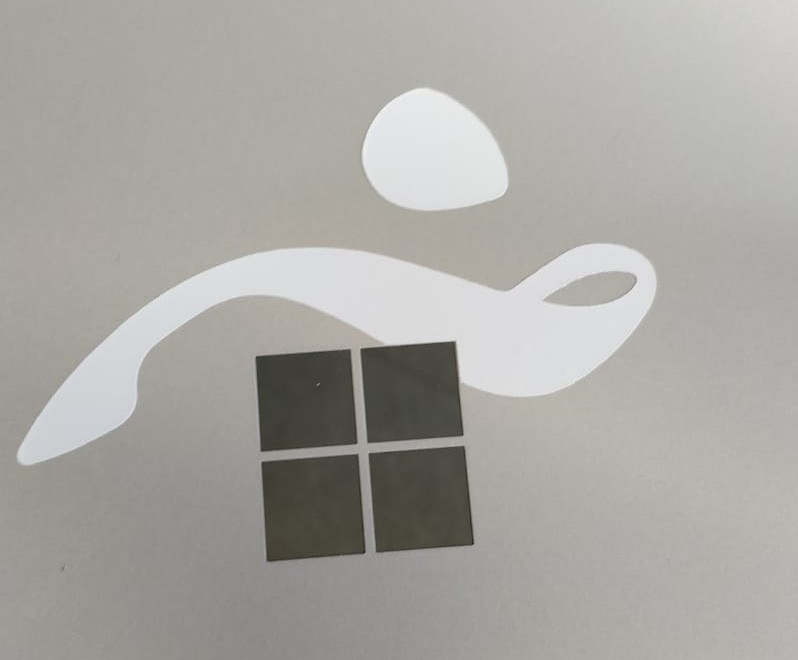
At the very beginning I began to measure the windows Logo on the back of my Laptop, since I wanted it to be part of my design.
Then I jumped into Adobe Illustrator, to actually create my design. First I layed out the reference for the windows logo. To do that I simply used the rectangle tool and typed in the values I had measured earlier.
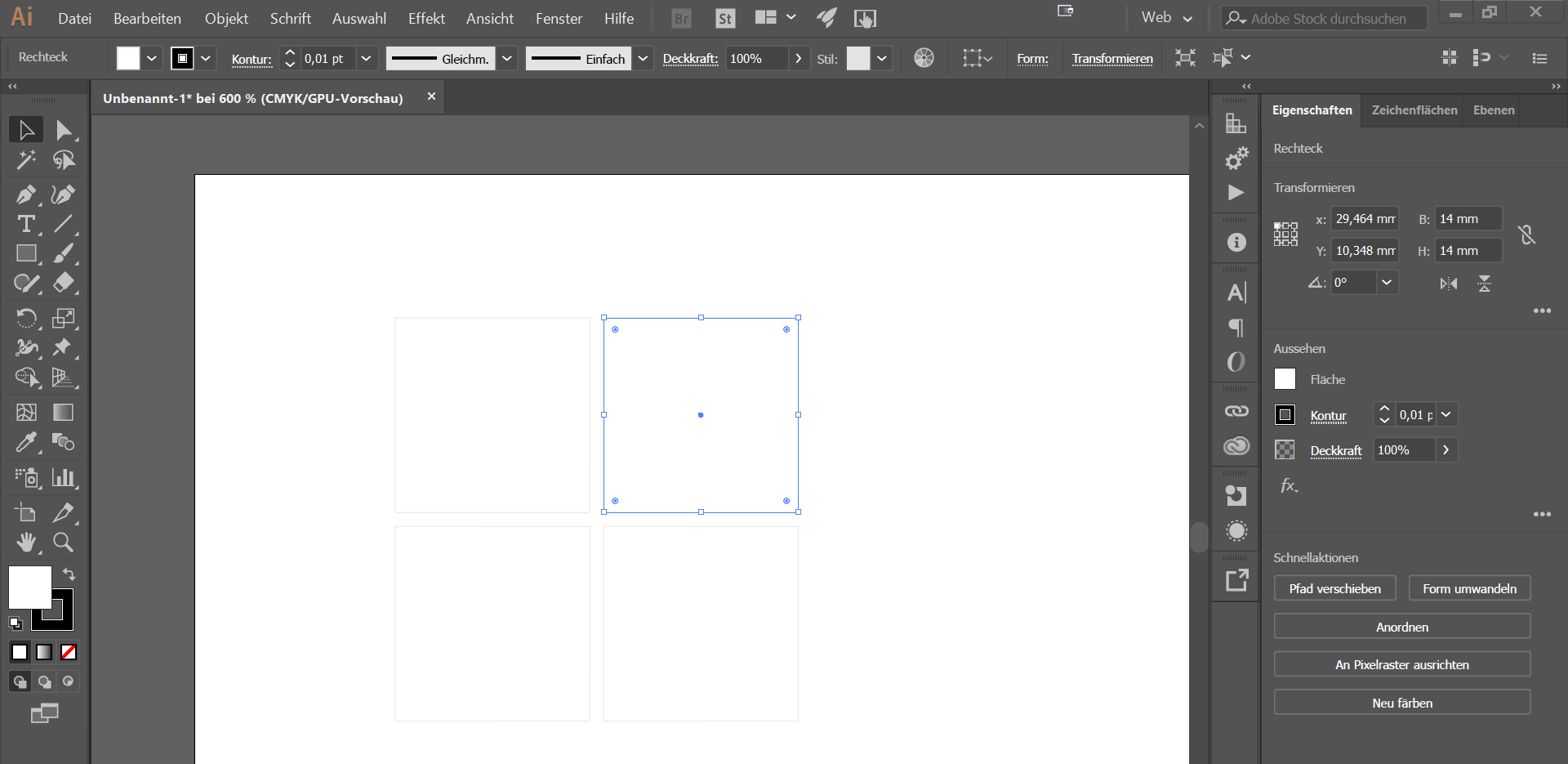
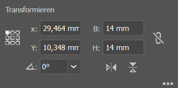
As you can see here, I just pasted what I measured into the transform dialogue of each rectangle.
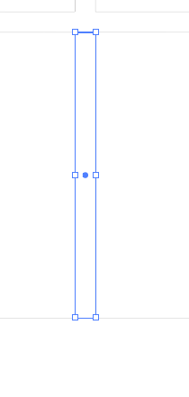
To have the rectangles spaced correctly, I used placeholder boxes, that had the exact same width that I measured earlier.
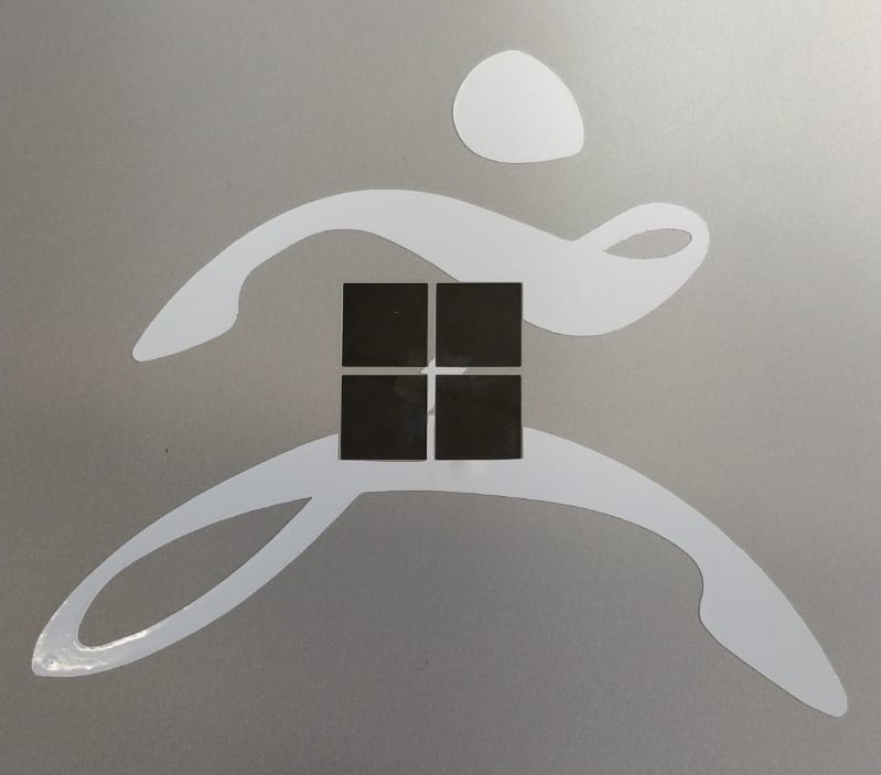
Then I imported the actual design I wanted to cut, for me that was the logo of my all time favourite 3d sculpting software "Zbrush".
The image if the Logo needed to be converted into a vector based format, to be able to work with the cutter. Luckily this is easily done in Illustrator by using the "image trace" feature.
There I just selected "Silhouettes" and clicked "extract". Now I adjusted the fill to none and the stroke to be black and 0,25pt, so I just have the outline of my design to work with.

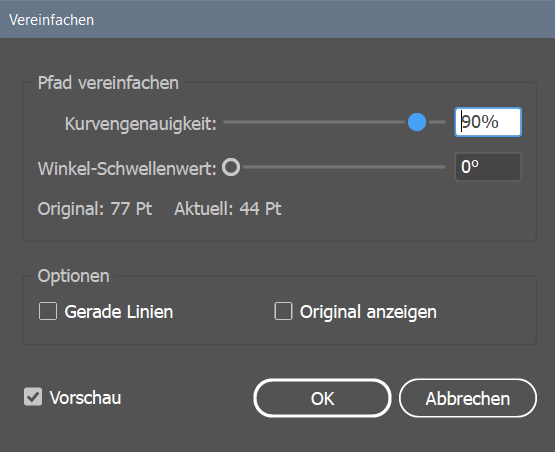
The Image trace algorithm left me with pretty ugly paths, which I countered by using the "simplify" tool at an accuracy of 90%.
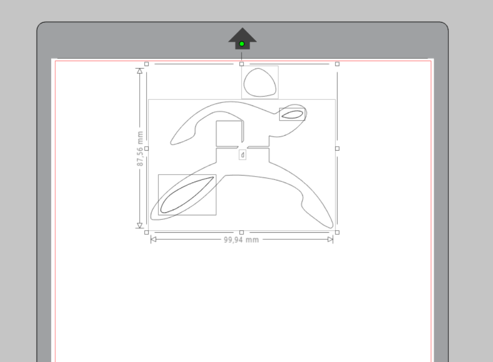
After then starting silhouette studio and loading my design, I positioned it to be roughtly in the top middle of the cutters area.
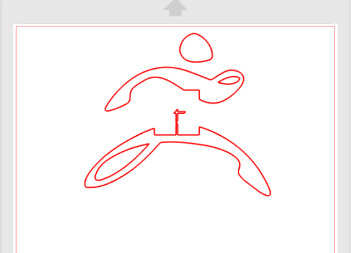
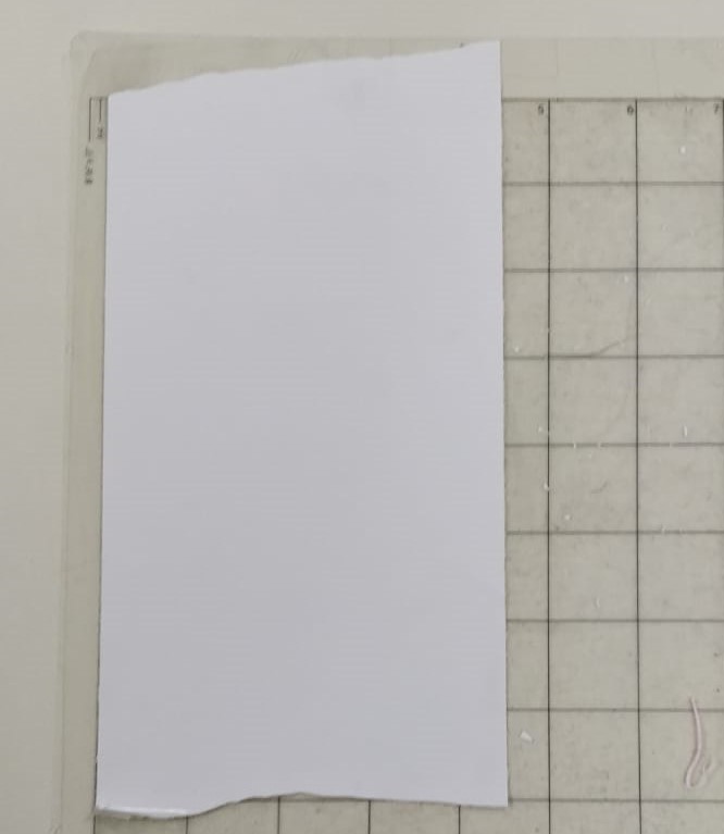
Then I changed the settings to match the device in our Fablab, which is a size of A4, and the carrier "Protrait"
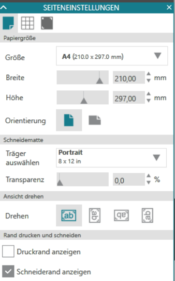
This is what my final ready to be cut design looked like.
Note to the device itself:
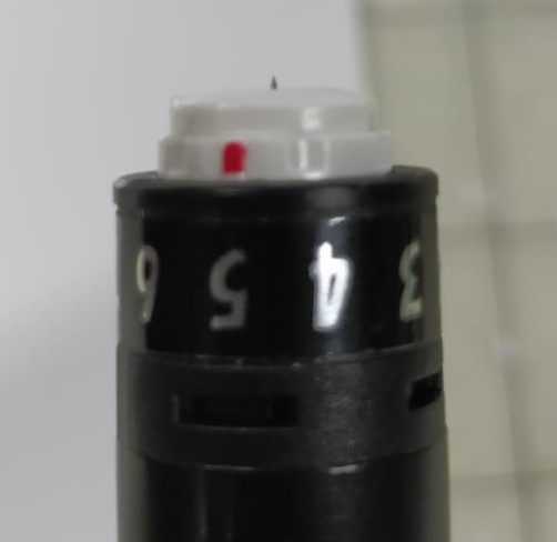
first of all you need to adjust the blade's level of pertusion (basically the depth of cut). Thsi is done, by alligning the red dot on the blade carriage with the arrow of the device's indentation and turning it. Higher numbers mean greater depths and vice versa.
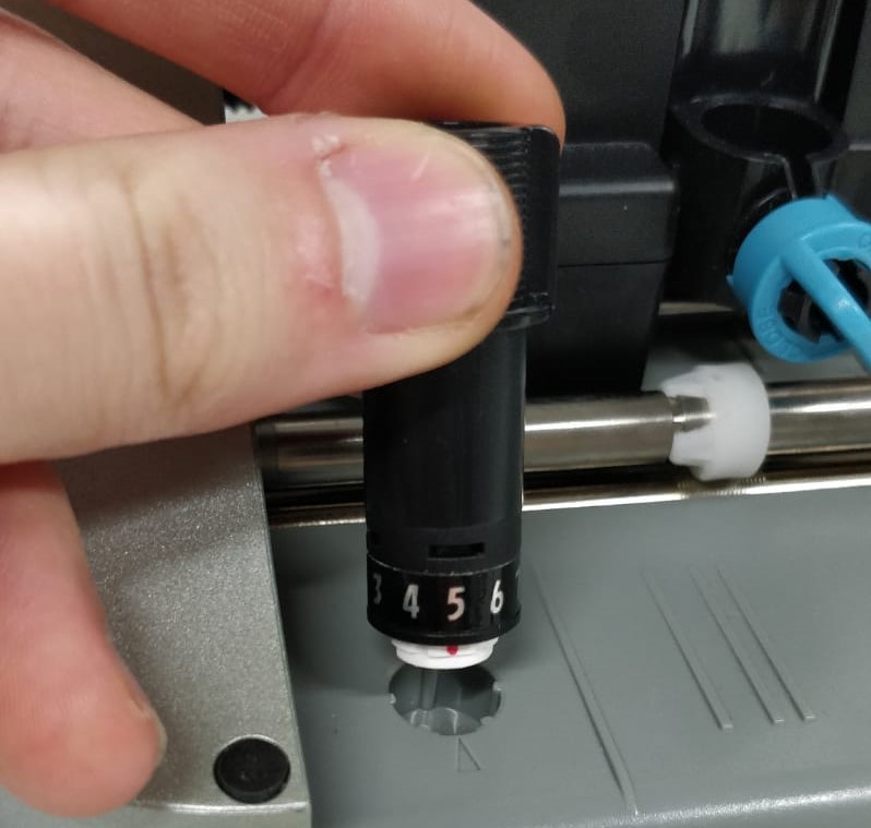
The depth should be set so the blade is bearly visible when looking at it form the side.
You then need to put the blade back into the device, to do that you need to stick it in and turn the blue lever clockwise until it clicks. then I positioned a piece of test vinly on the carrier.
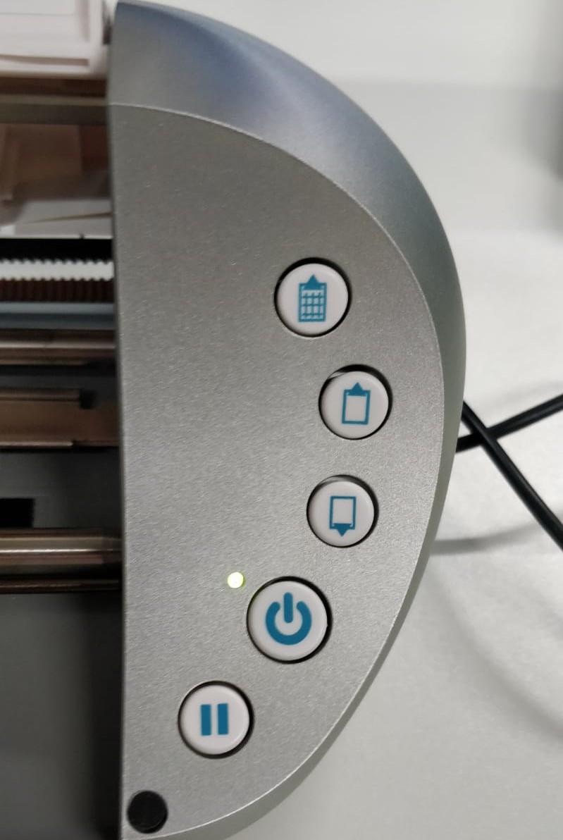
Quick explanation of the machienes few controls. The top most button feeds the first few cm of the carrier into the machiene. The two buttons below feed more of the carrier into the machiene of retract the carrier out of it. The other two buttons are Power and pause.
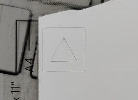
In the software you can choose to test your settings, this will cut a little triangle with a rectangle around it, to be able to see the cut depth or if the blade is dull.
In my case everything was fine and I could finally cut out my desing.
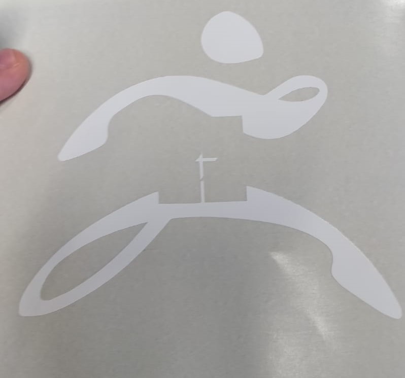
After cutting, which took about 10 seconds, I removed the access vinyl from my piece and ended up with this:
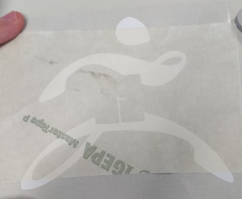
I then stuck a piece of masking tape to my design, to be able to transfer it easily.
Because I needed to see where I was transfering my design very exactly, that turned out not to be that good of a technique for my case.
I tried cutting the masking tape back in the relevant areas, but that also did not help very much, so I decided to simply freehand it.
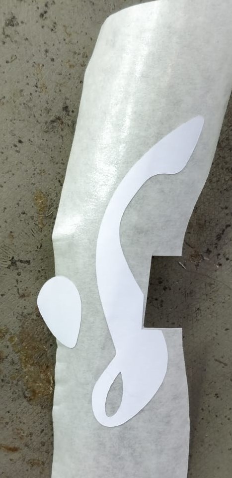
And that turned out to be the best thing I could do, application went flawless and the results look really good in my humble opinion.
For the Parametric design, I used the Software "Fusion 360", the creation of the sketch itself was very basic and only consisted of using the "line" tool. The basic features of Fusion360 for CAD are documented in last weeks assignment.
After the initial design was finished, it was time to make it parametric. This was done by adding dimensions to all of the designs edges, by utilizing the keyboard shortcut "d" and clicking on the desired edge.
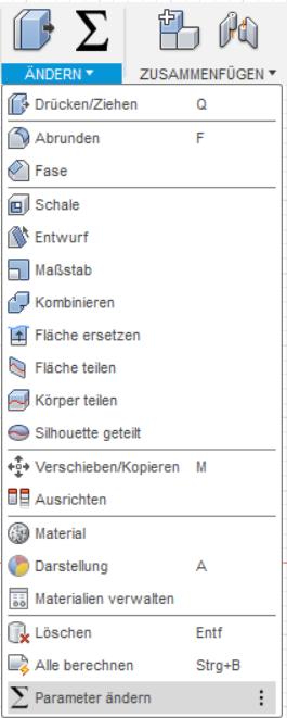
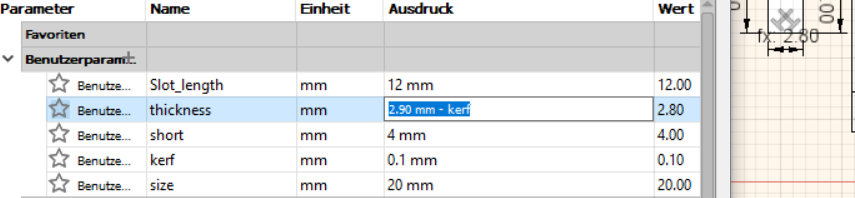
Then I created the actual parameters in the "change parameter" dialogue.
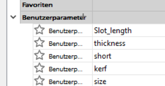
This is done by clicking the little plus sign on the "user parameters" field. There you can add a name for the parameter, as well as an mathematical expression and an initial value.
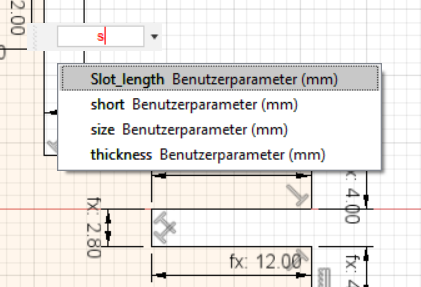
Once that is done you can add the name of the parameter to the dimension you want, by double clicking it and control that value in the change parameter spreadsheet.
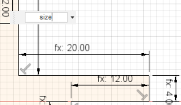
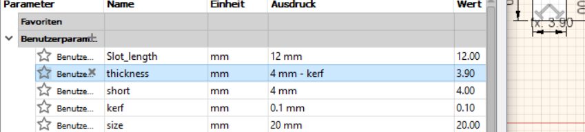
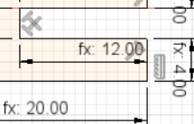
As you can see below, when I change the "Thickness" value, the dimension on the right changes accordingly.
What you can also see here is that the Thickness value consists of some number - "kerf", kerf is another parameter I set, meaning you can interconnect parameters with each other.
To make the parametric design work, it also needs constrains. In my case that were the "orthographic" and the "horizontal/Vertical" constrains.
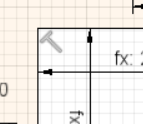
The orthographic constrain is used, whenever a line needs to stay at an 90° angle to another one. It is added by first clicking it in the right hand side toolbar and then selecting two edges it should be used on.
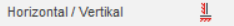
The Horizontal/Vertical constrain is used, whenever a line needs to stay either horizontal or vertical (surprise surprise..). It is also added by clicking it in the right hand side toolbar and selecting the edge it should be applied to.
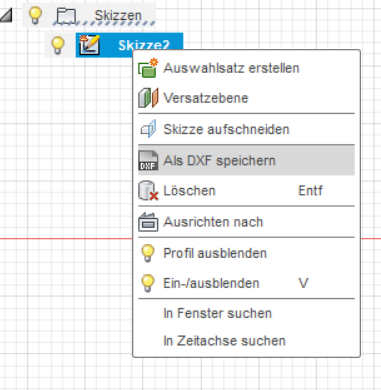
After the design was finished, it was exported as a .DXF file, by right clicking the sketch and selecting "save as DXF".
Then it was time to actually cut the design on the lasercutter. Basic usage of the cutter is documented in this weeks group assignment and will not be further elaborated here.
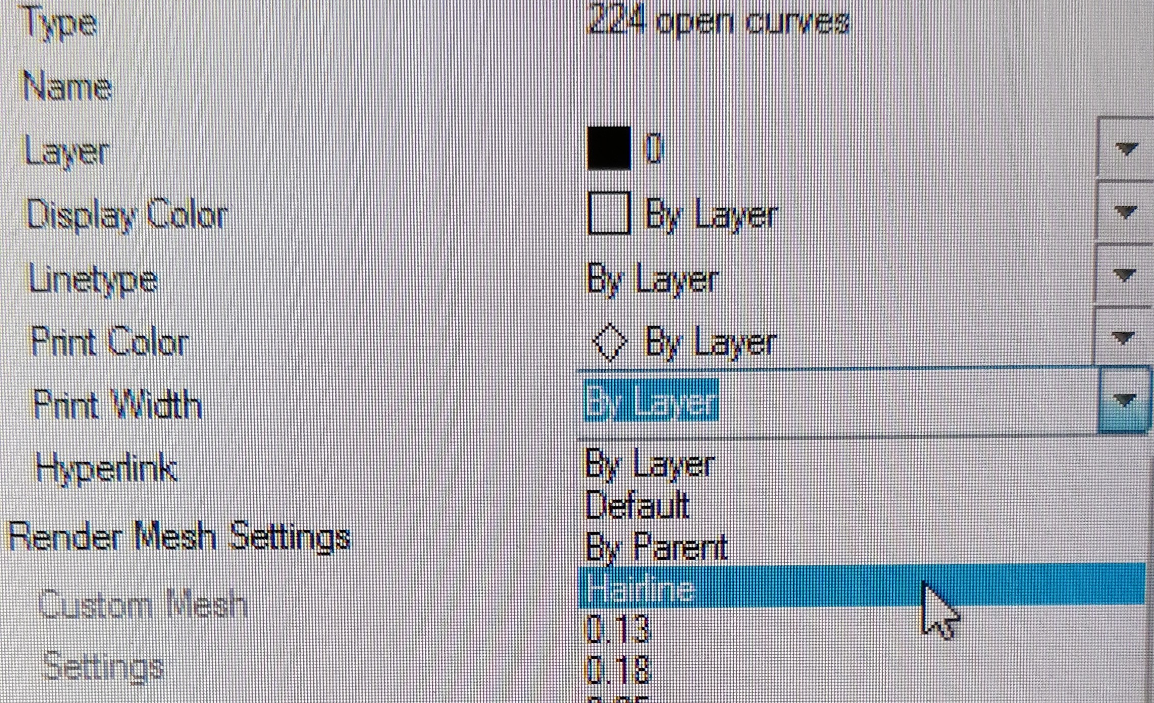
First I wanted to make a test, to evaluate my kerf settings were right. For that I opened my dxf file in Rhino, here I changed the print width to "hairline" so my design is actually able to be cut.
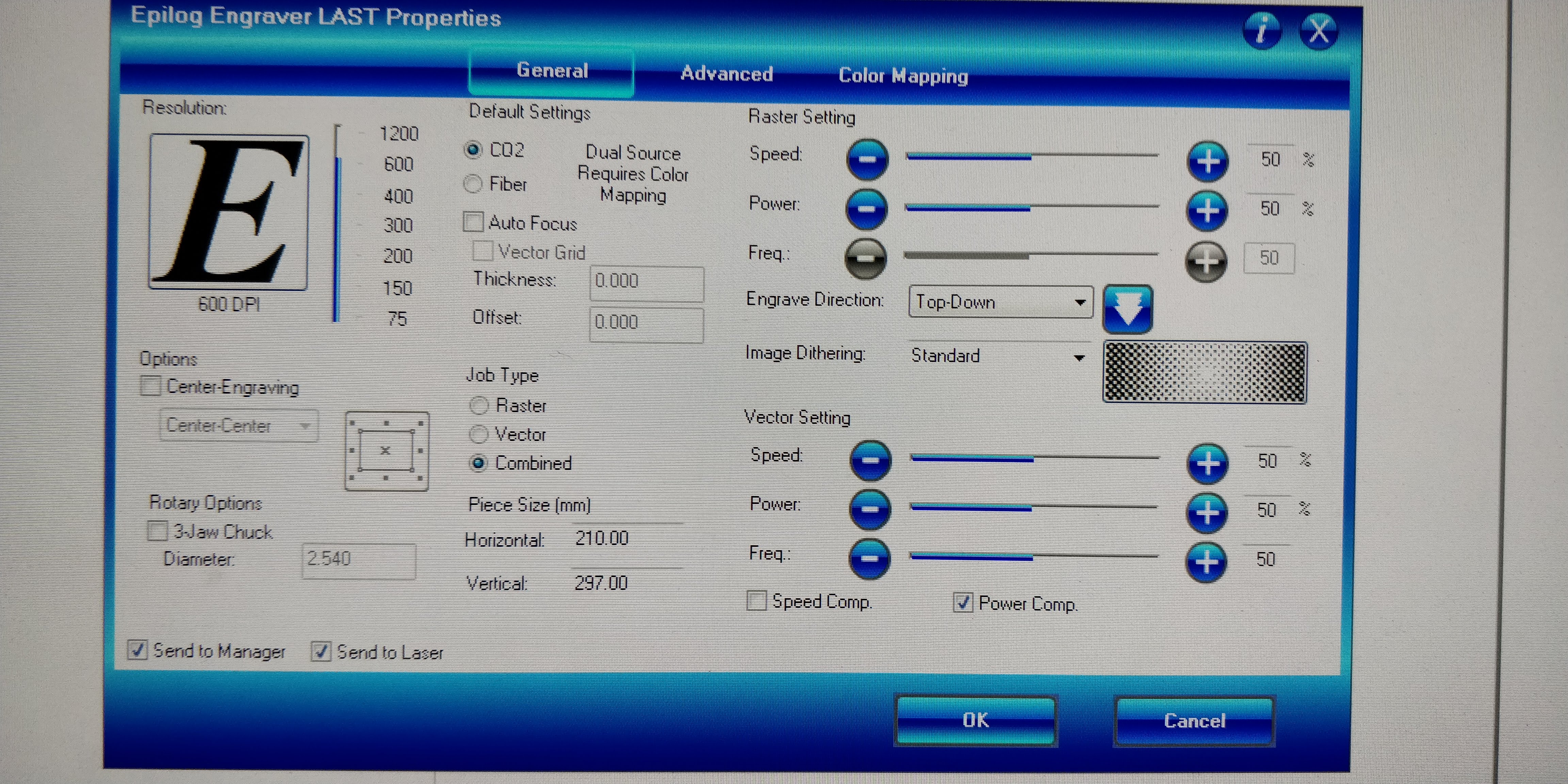
Then I setup the cutters parameters according to the results we got in the group assignment. In this case that Speed : 27%, Power: 100% and Frequency: 10%. These were set in this configuration window, an important thing to note is that since I only want to cut, I can set the Job type to "vector".
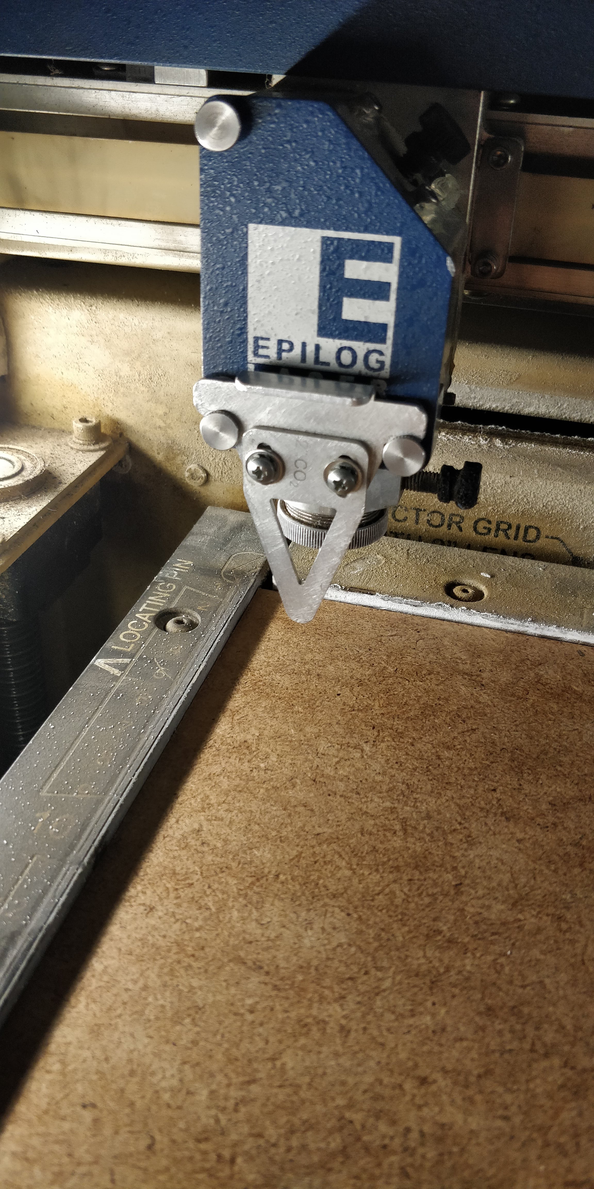
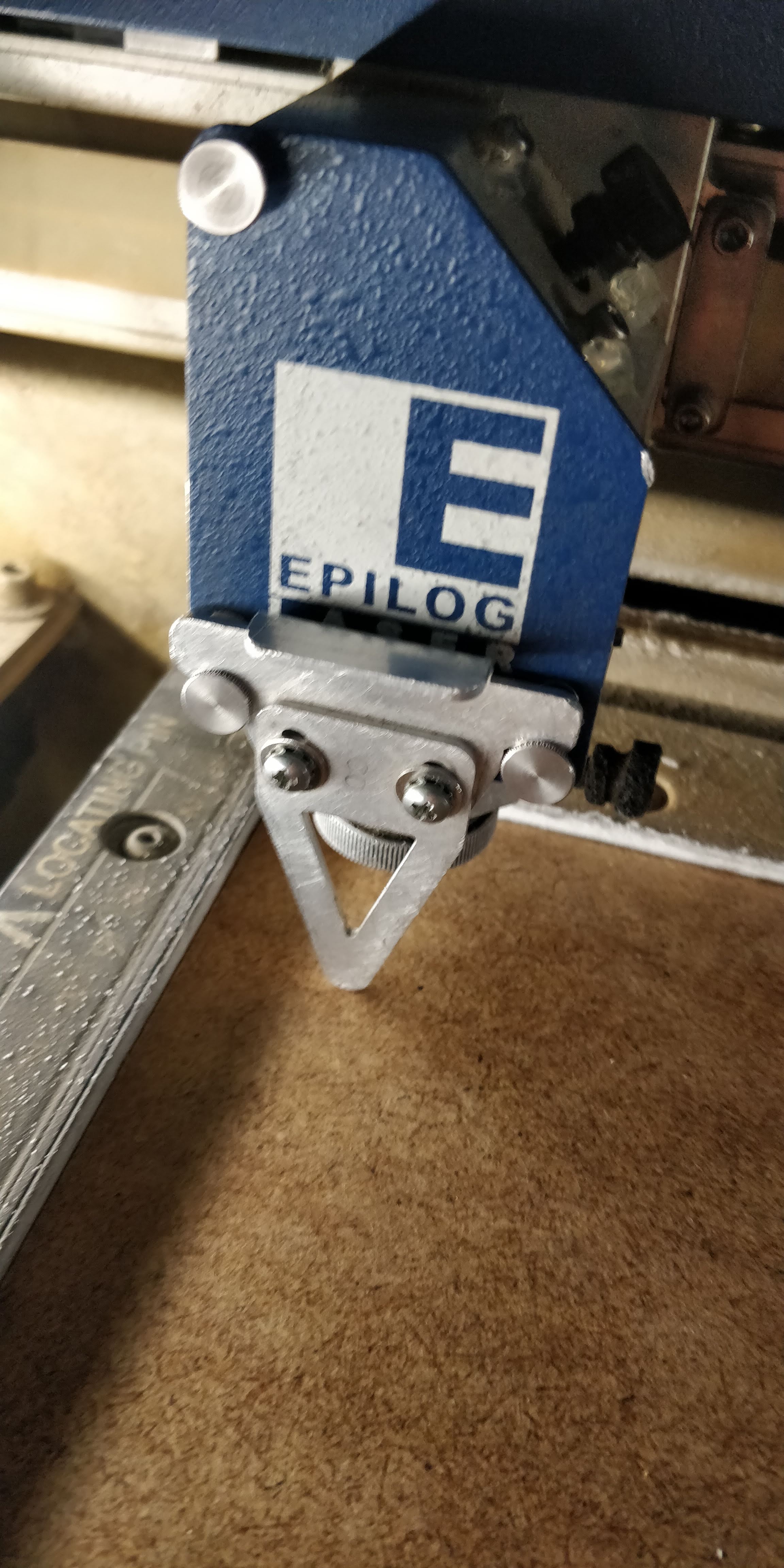
Before you can start cutting though, you need to focus the laser to be able to cut. For that there is a little triangle tool that can be hung onto the lens. When installed correctly, it should look like this.
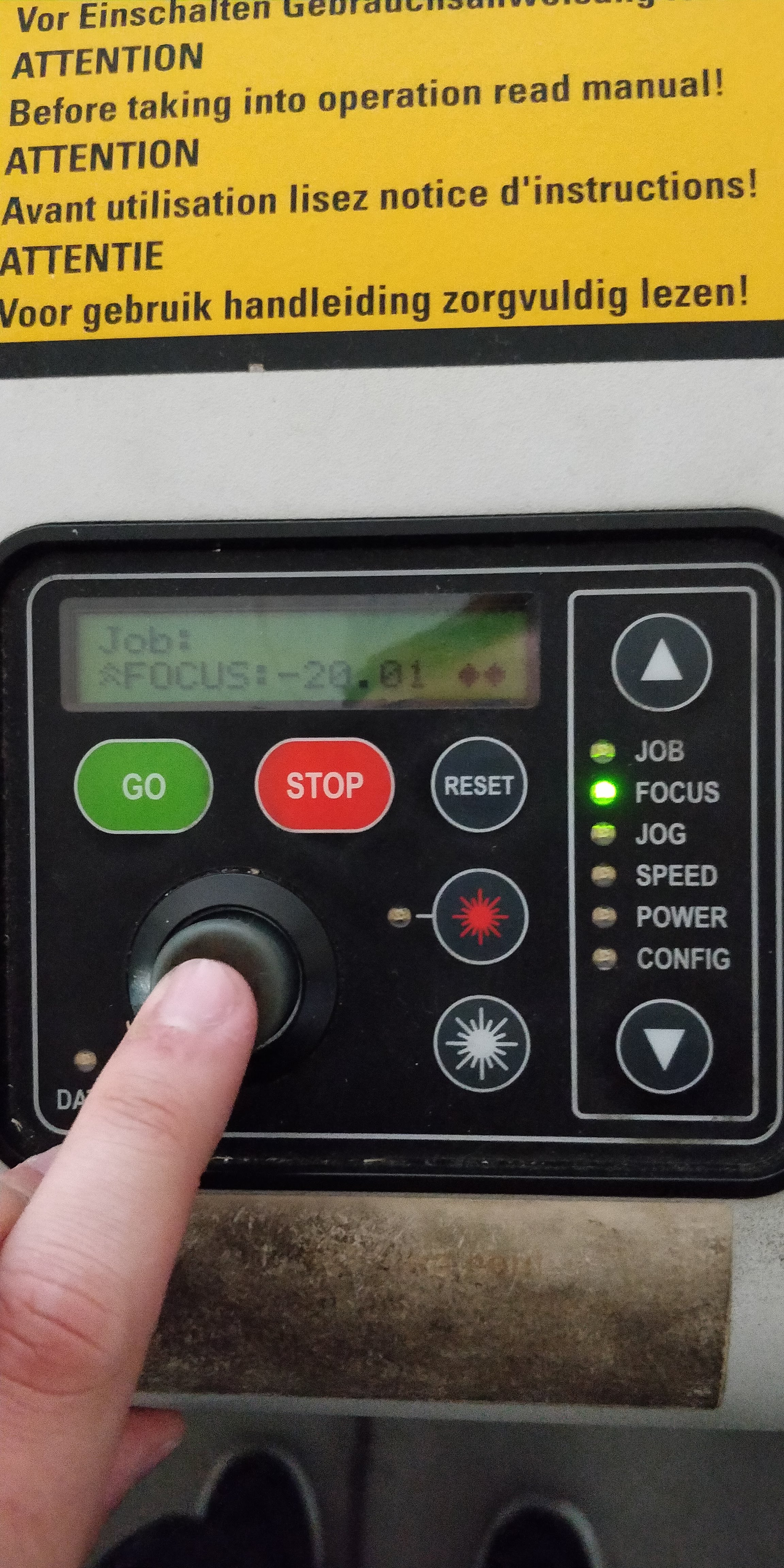
On the laser itself, you then use the white arrows to navigate to "focus". After that you can use the analog stick to move the bed up and down.
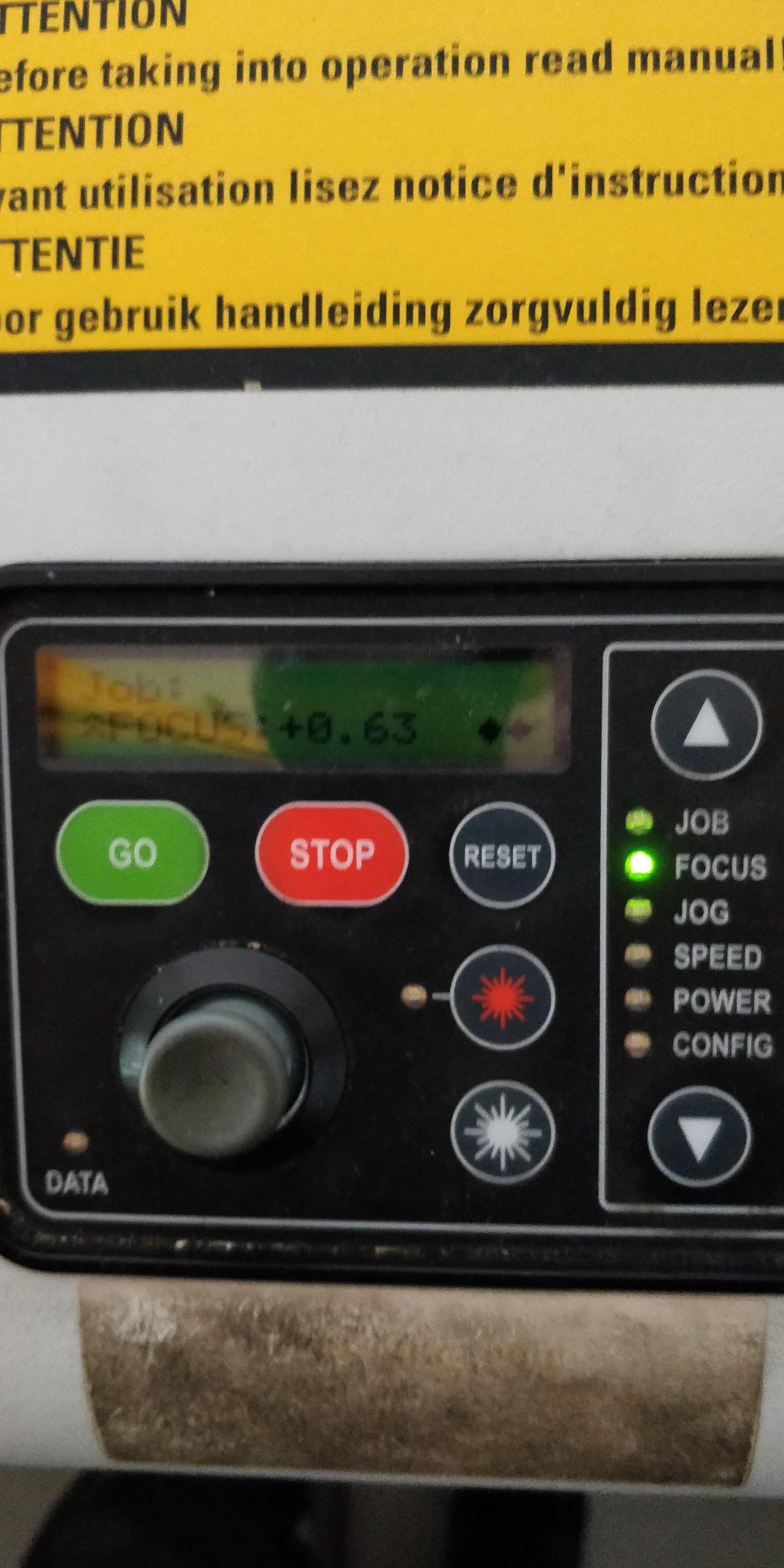
When focused correctly, the triangle tool should baerly touch the surface of whatever you want to cut.
To confirm your focus, you have to press the analog stick in. You know it worked, if the displayed number changes to "0".
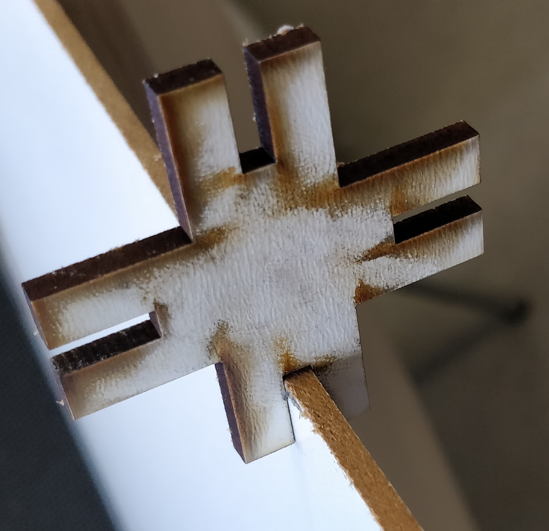
This turned out to work on the very first try as you can see here:
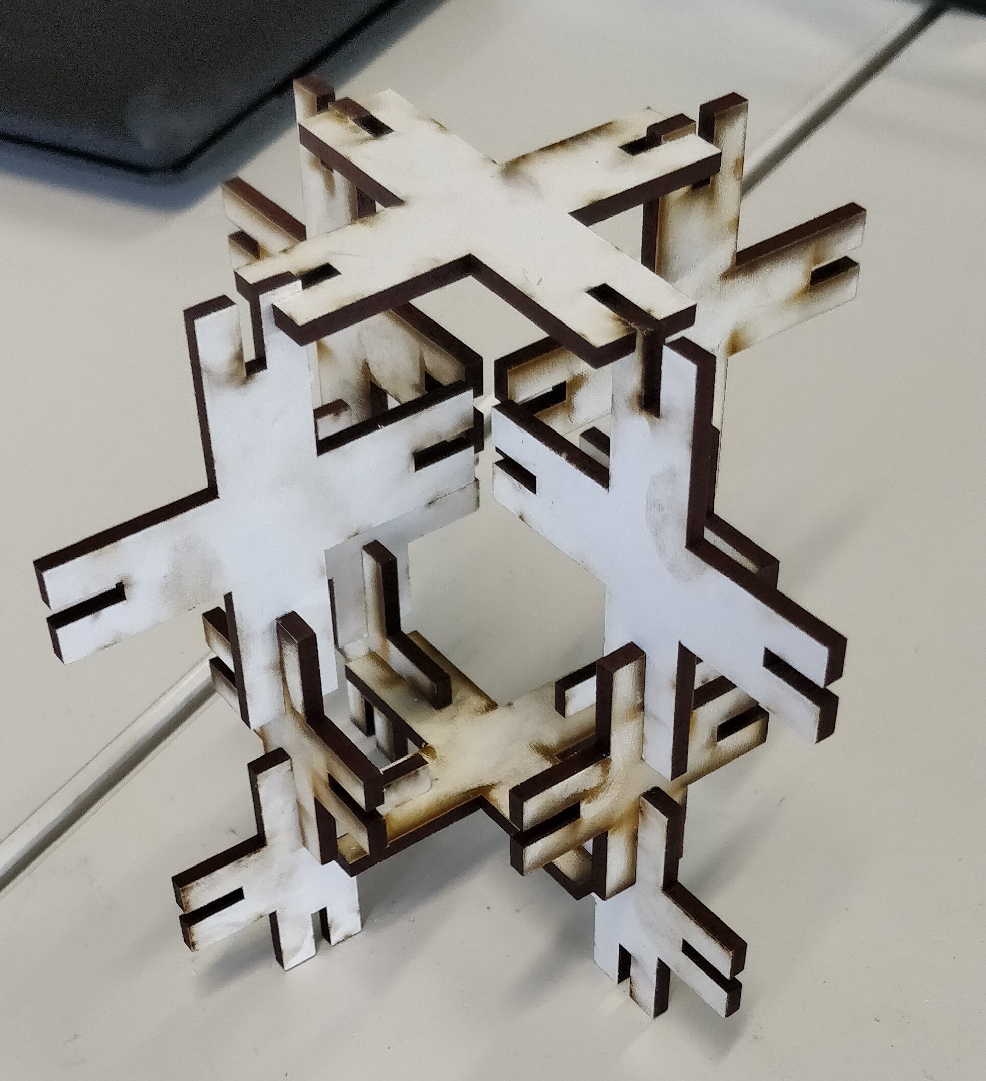
I then cut out a whole bunch of these pieces and decided to change one of the parameters in my design to have a few bigger pieces as well. After that I followed the same steps to also cut out a bunch of these.
Download all the used files!
Here is what I did:
At the very beginning I began to measure the windows Logo on the back of my Laptop, since I wanted it to be part of my design.
Then I jumped into Adobe Illustrator, to actually create my design. First I layed out the reference for the windows logo. To do that I simply used the rectangle tool and typed in the values I had measured earlier.
As you can see here, I just pasted what I measured into the transform dialogue of each rectangle.
To have the rectangles spaced correctly, I used placeholder boxes, that had the exact same width that I measured earlier.
Then I imported the actual design I wanted to cut, for me that was the logo of my all time favourite 3d sculpting software "Zbrush".
The image if the Logo needed to be converted into a vector based format, to be able to work with the cutter. Luckily this is easily done in Illustrator by using the "image trace" feature.
There I just selected "Silhouettes" and clicked "extract". Now I adjusted the fill to none and the stroke to be black and 0,25pt, so I just have the outline of my design to work with.
The Image trace algorithm left me with pretty ugly paths, which I countered by using the "simplify" tool at an accuracy of 90%.
After then starting silhouette studio and loading my design, I positioned it to be roughtly in the top middle of the cutters area.
Then I changed the settings to match the device in our Fablab, which is a size of A4, and the carrier "Protrait"
This is what my final ready to be cut design looked like.
Note to the device itself:
first of all you need to adjust the blade's level of pertusion (basically the depth of cut). Thsi is done, by alligning the red dot on the blade carriage with the arrow of the device's indentation and turning it. Higher numbers mean greater depths and vice versa.
The depth should be set so the blade is bearly visible when looking at it form the side.
You then need to put the blade back into the device, to do that you need to stick it in and turn the blue lever clockwise until it clicks. then I positioned a piece of test vinly on the carrier.
Quick explanation of the machienes few controls. The top most button feeds the first few cm of the carrier into the machiene. The two buttons below feed more of the carrier into the machiene of retract the carrier out of it. The other two buttons are Power and pause.
In the software you can choose to test your settings, this will cut a little triangle with a rectangle around it, to be able to see the cut depth or if the blade is dull.
In my case everything was fine and I could finally cut out my desing.
After cutting, which took about 10 seconds, I removed the access vinyl from my piece and ended up with this:
I then stuck a piece of masking tape to my design, to be able to transfer it easily.
Because I needed to see where I was transfering my design very exactly, that turned out not to be that good of a technique for my case.
I tried cutting the masking tape back in the relevant areas, but that also did not help very much, so I decided to simply freehand it.
And that turned out to be the best thing I could do, application went flawless and the results look really good in my humble opinion.
Parametric design and cutting
For the Parametric design, I used the Software "Fusion 360", the creation of the sketch itself was very basic and only consisted of using the "line" tool. The basic features of Fusion360 for CAD are documented in last weeks assignment.
After the initial design was finished, it was time to make it parametric. This was done by adding dimensions to all of the designs edges, by utilizing the keyboard shortcut "d" and clicking on the desired edge.
Then I created the actual parameters in the "change parameter" dialogue.
This is done by clicking the little plus sign on the "user parameters" field. There you can add a name for the parameter, as well as an mathematical expression and an initial value.
Once that is done you can add the name of the parameter to the dimension you want, by double clicking it and control that value in the change parameter spreadsheet.
As you can see below, when I change the "Thickness" value, the dimension on the right changes accordingly.
What you can also see here is that the Thickness value consists of some number - "kerf", kerf is another parameter I set, meaning you can interconnect parameters with each other.
To make the parametric design work, it also needs constrains. In my case that were the "orthographic" and the "horizontal/Vertical" constrains.
The orthographic constrain is used, whenever a line needs to stay at an 90° angle to another one. It is added by first clicking it in the right hand side toolbar and then selecting two edges it should be used on.
The Horizontal/Vertical constrain is used, whenever a line needs to stay either horizontal or vertical (surprise surprise..). It is also added by clicking it in the right hand side toolbar and selecting the edge it should be applied to.
After the design was finished, it was exported as a .DXF file, by right clicking the sketch and selecting "save as DXF".
Then it was time to actually cut the design on the lasercutter. Basic usage of the cutter is documented in this weeks group assignment and will not be further elaborated here.
First I wanted to make a test, to evaluate my kerf settings were right. For that I opened my dxf file in Rhino, here I changed the print width to "hairline" so my design is actually able to be cut.
Then I setup the cutters parameters according to the results we got in the group assignment. In this case that Speed : 27%, Power: 100% and Frequency: 10%. These were set in this configuration window, an important thing to note is that since I only want to cut, I can set the Job type to "vector".
Before you can start cutting though, you need to focus the laser to be able to cut. For that there is a little triangle tool that can be hung onto the lens. When installed correctly, it should look like this.
On the laser itself, you then use the white arrows to navigate to "focus". After that you can use the analog stick to move the bed up and down.
When focused correctly, the triangle tool should baerly touch the surface of whatever you want to cut.
To confirm your focus, you have to press the analog stick in. You know it worked, if the displayed number changes to "0".
This turned out to work on the very first try as you can see here:
I then cut out a whole bunch of these pieces and decided to change one of the parameters in my design to have a few bigger pieces as well. After that I followed the same steps to also cut out a bunch of these.
Final Result
Download all the used files!