7. Electronics design
In this week, I learned basic skills to create own electrical circuits.
- How to use softwares to design own electrical circuits
- Basic flow to write down simple codes into my milled board
Group assignment
Our group assignment is described here.
Individual assignment
Redrawing the echo hello-world board by adding some other electrical components
For this assignment I added a button anf LED(red). This is a minimum requirement of redrawing the board.
To redraw the board, I used Eagle software, becasue there have been a lot of guide books and I received small lesson from our local instructor before this academy.
The guidebook I have been using is this.
Designing electrical circuit
First of all, I should imitate “the echo hello-world board ” without any extra components. I downloaded original png file from here and chose survey each comonents and wiring very carefully.

As a result, all components for initial board to redraw were
- R1:Resistance 10k [ohm]
- C1: Capacitor 1u [F]
- IC1: Attiny 44
- 20MHz: Resonator 20M[Hz]
- J1 ISP: Pin header 2x3
- J2 FTDI: Pin header 1X6
After that, I desinged a small electrical circuit to add a button and a LED.
Rough skecth of the extra circuit is shown as below.
One of the important points is that we have to think of current path when button (switch) is turned on and off.
Particularly when button is off, connection between a power supply (5V) and Attiny44 does not go to the “GND”.
Then, wihtout any resigter between them, electrical volt (5V) will be applied to Attiny44 directly and Attiny will be damaged.
To avoid the damaging, we have to insert a register between the power supply and Attiny44.
“electrical circuit”
Moreover, to make the LED bright by appropriate blightness, I also had to insert register between the LED and GND.
Finally, the extra electrical components were as following.
- Tactile Switch
- LED
- Resistance 1k [ohm]
- Resistance 10k [ohm]
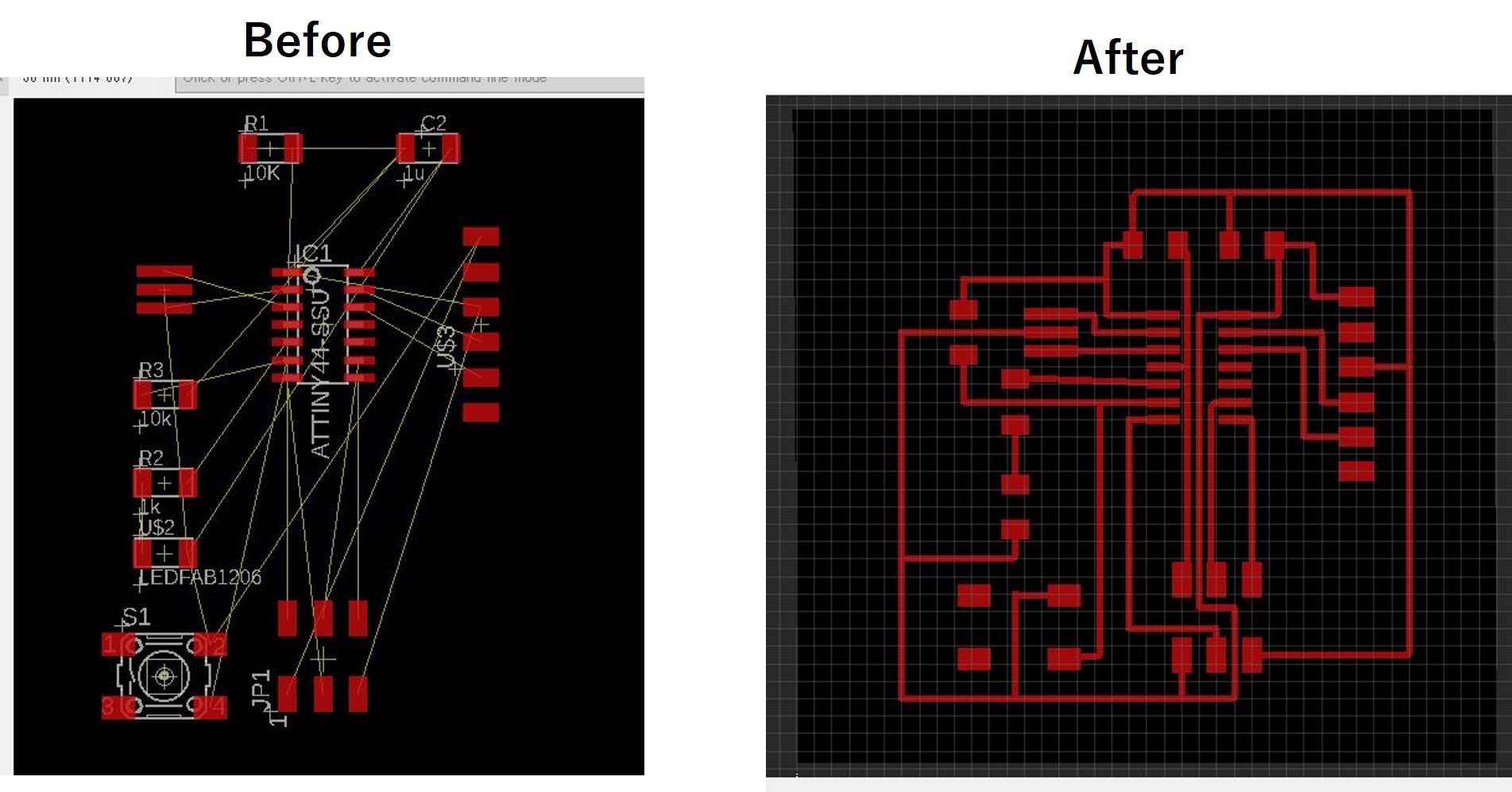
Drawing the electrical circuit on the software
Before starting Eagle, I imported a special liblary for electrical components for Fabacademy into Eagle library.
After that, I could choose each component from the library.
To choose components from the library, we should command “add” in the commad space.
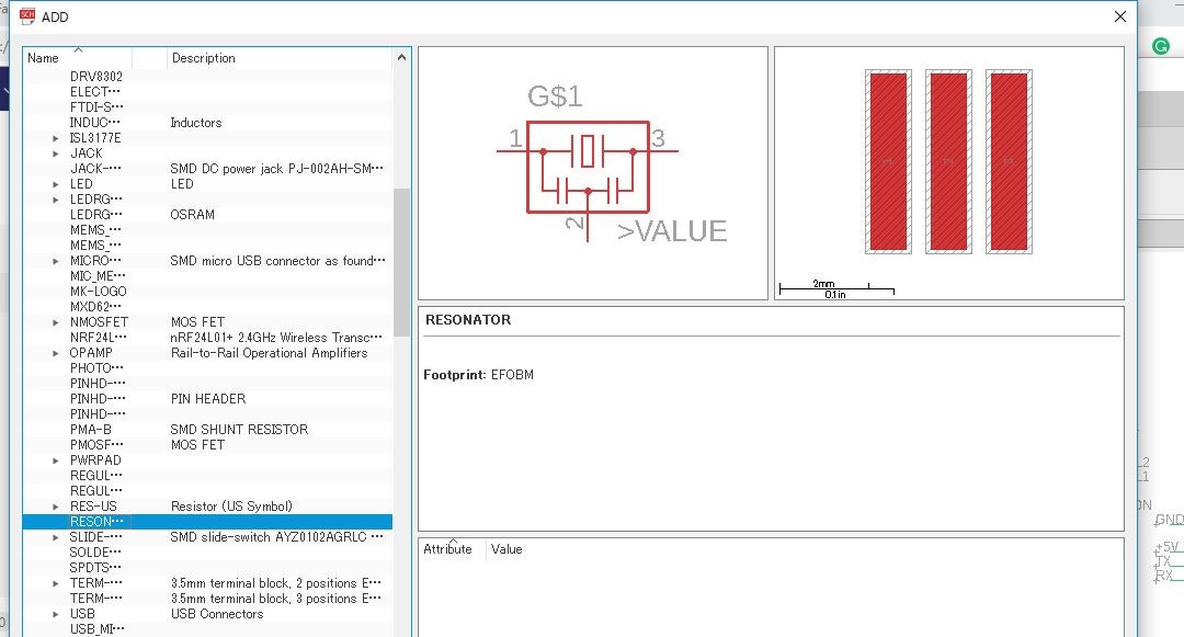
And by wiring these components, desired electrical circuit was completed in Eagle work space.
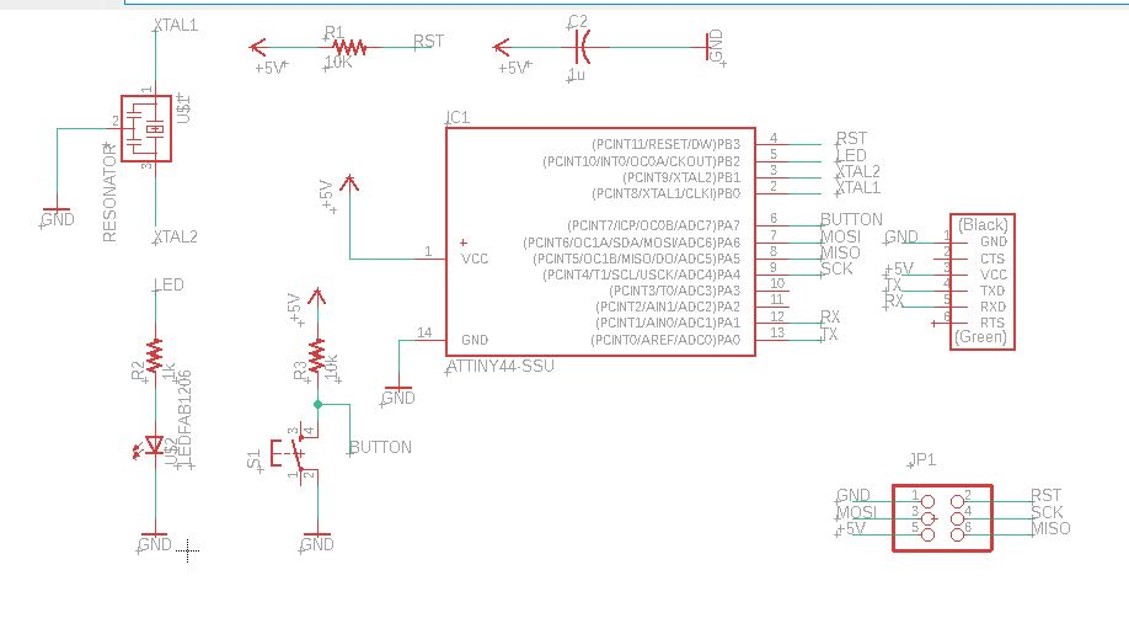
However, it was too early to feel happy in this time, because I did not check whether my designed circuit did not have any problems in terms of wiring.
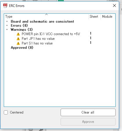
Then, to check verification of my circuit, I typed “erc” meaning electrical rule check.
The result showed there was no wiring problems.
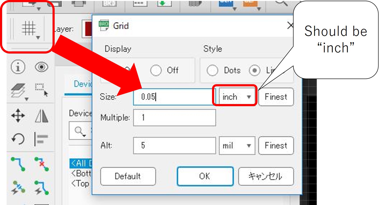
After checking verification, clicking “generate/swicth to board ” led to a workspace for creating PCB board. In this workspace, we could generate circuit paths that would be milled. Before generating the paths, the local instructor adviced us to set grid value from 0.05 inch to 0.025 inch.
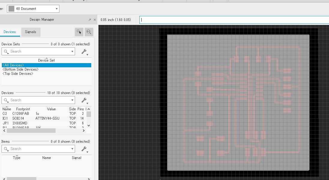
Next, I defined outline of the PCB board in different layer. In that case, the layer was “48:document”.
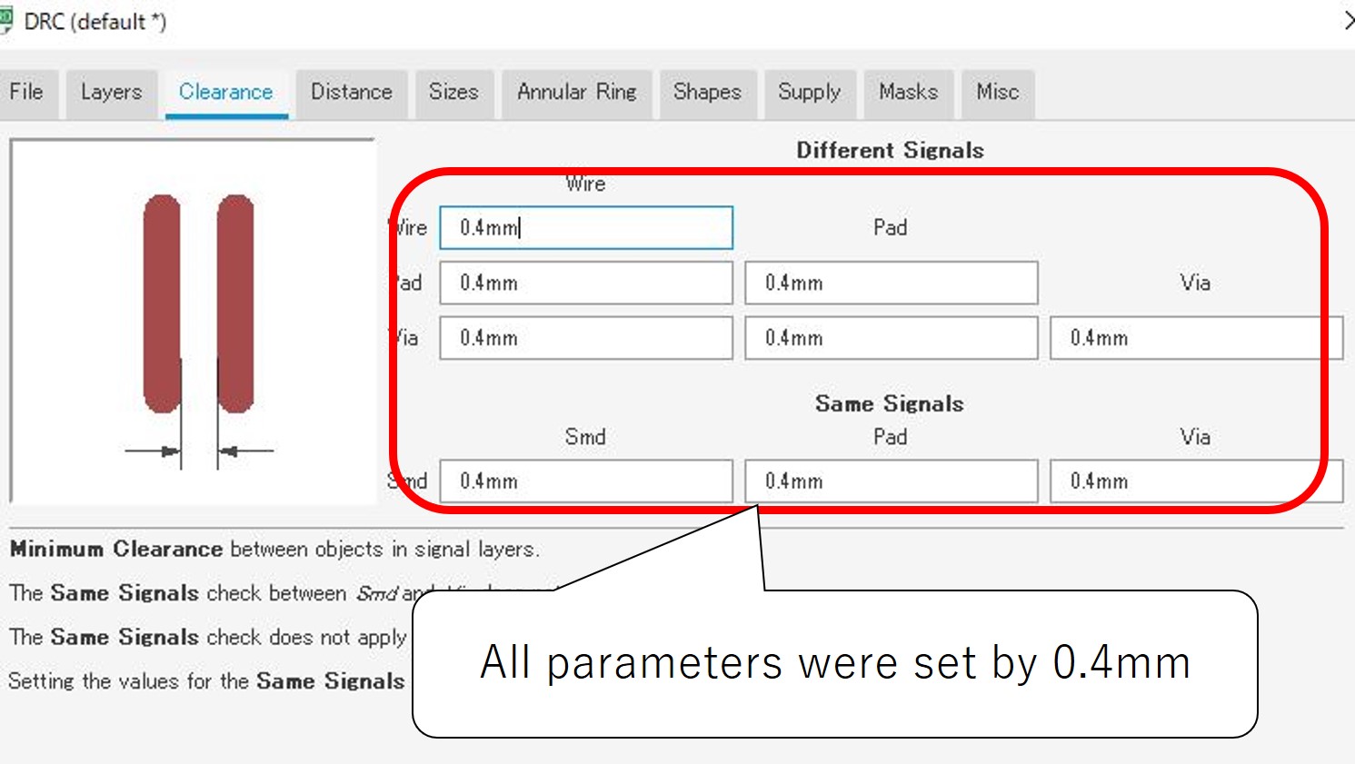
Finally DRC “design rule check” was done to set all width parameters as 0.4mm.
This designed circuit were exported as “top.png” and “outline.png” files.
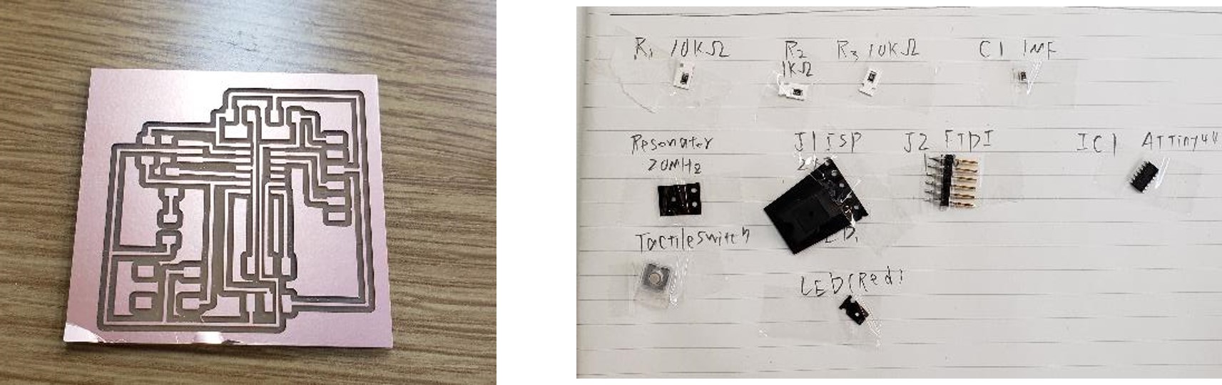
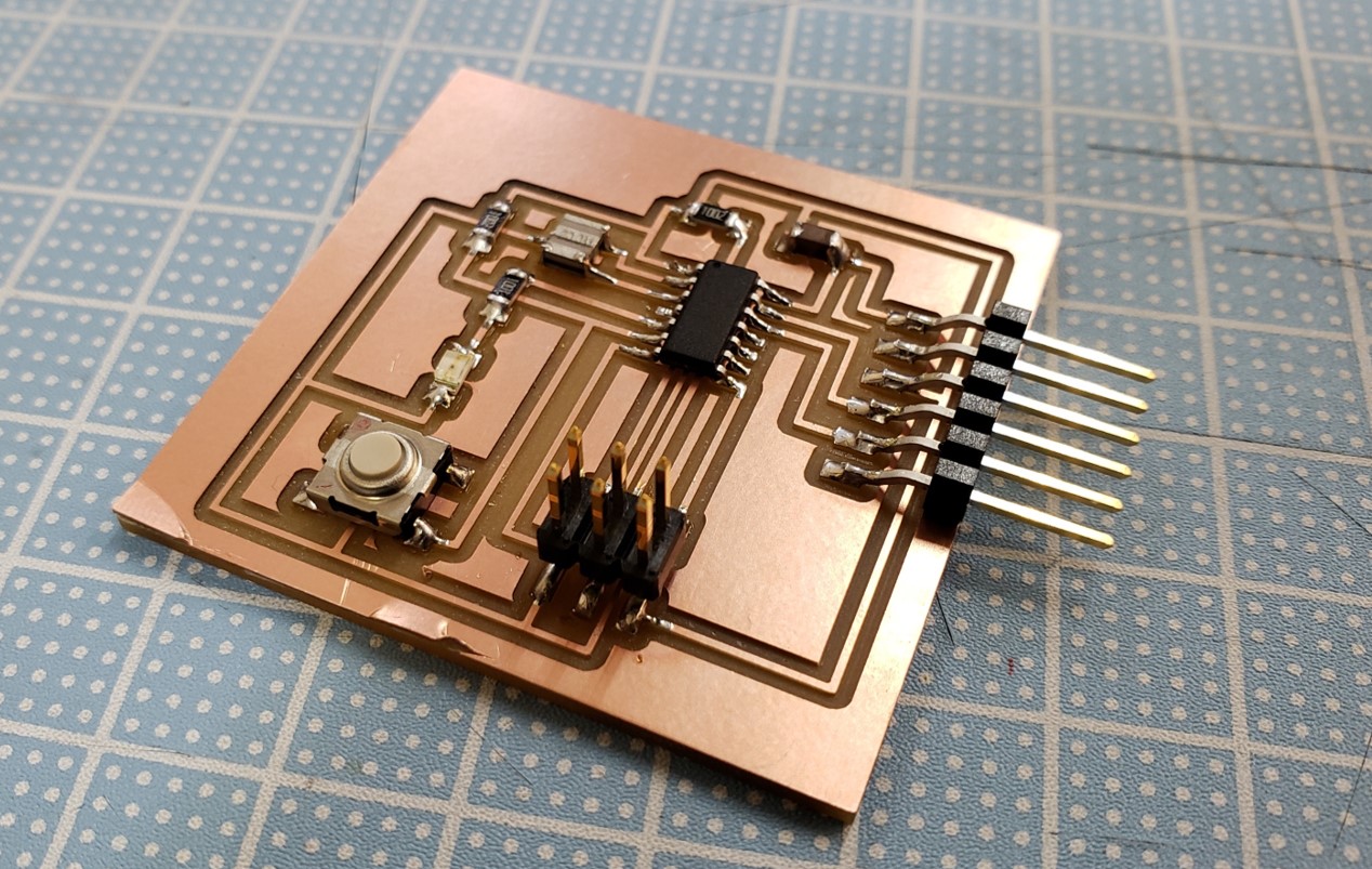
Milling and soldering my PCB board
By following basic rules I learned in week5:electronics production, I created my PCB board and soldered all components.
Test own board
To check my cretaed board works, I tested “echo hello-world” code following this tutorial.
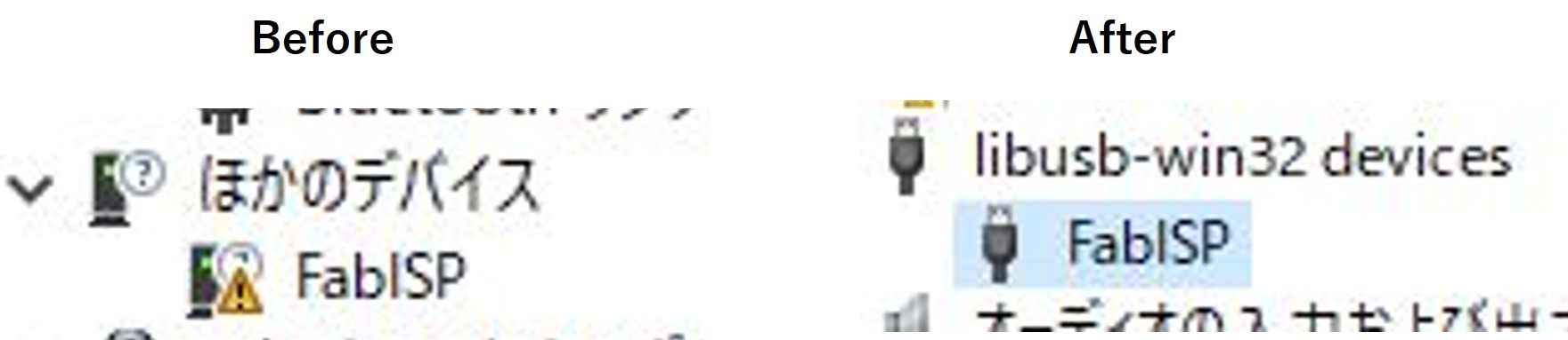
First of all, I tried to use my FabISP made in week5:electronics production like below structure using FTDI USB Serial adapter. However, the result in week5 showed that although my laptop recognized my FabISP, the FabISP was recognized as other devices (Not USB device!!). Then I used Zadik to install a driver for my FabISP. Installing the driver made my FabISP as USB device.
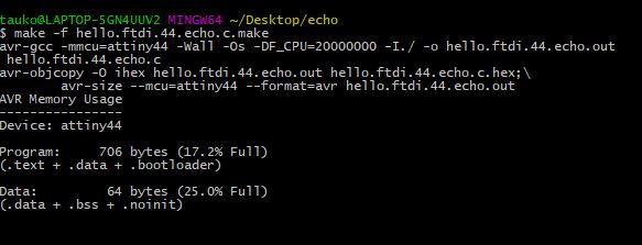
After that I typed below commands
make -f hello.ftdi.44.echo.c.make
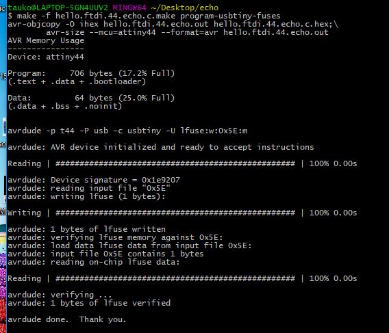
sudo make -f hello.ftdi.44.echo.c.make program-usbtiny-fuses
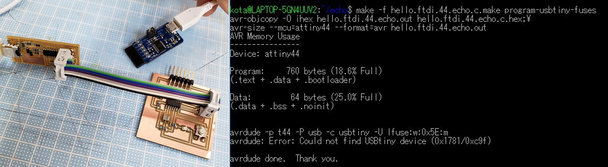
But it failed. The error message said “the laptop canoot find USB device”, so I thought the cause was the same as in week5:electronics production.
I tried again by using arduino. Procedures were the same as in week5.
- Added some lines in the make file
program-stk500v1: $(PROJECT).hex avrdude -p t44 -P /dev/ttyS7 -b19200 -c stk500v1 -U flash:w:$(PROJECT).c.hex

program-stk500v1-fuses: $(PROJECT).hex avrdude -p t44 -P /dev/ttyS7 -b19200 -c stk500v1 -U lfuse:w:0x5E:m
- Made USB port connected with the Arduino have authrization
sudo chmod 666 /dev/ttyS7
(Note:At that time, the Arduino was connected to "COM7"
- Changed the 2nd make command a little bit
sudo make -f hello.ftdi.44.echo.c.make program-stk500v1-fuses
After that there was no error message, but it took too long time to complete the procedure. Then I guessed it also failed.
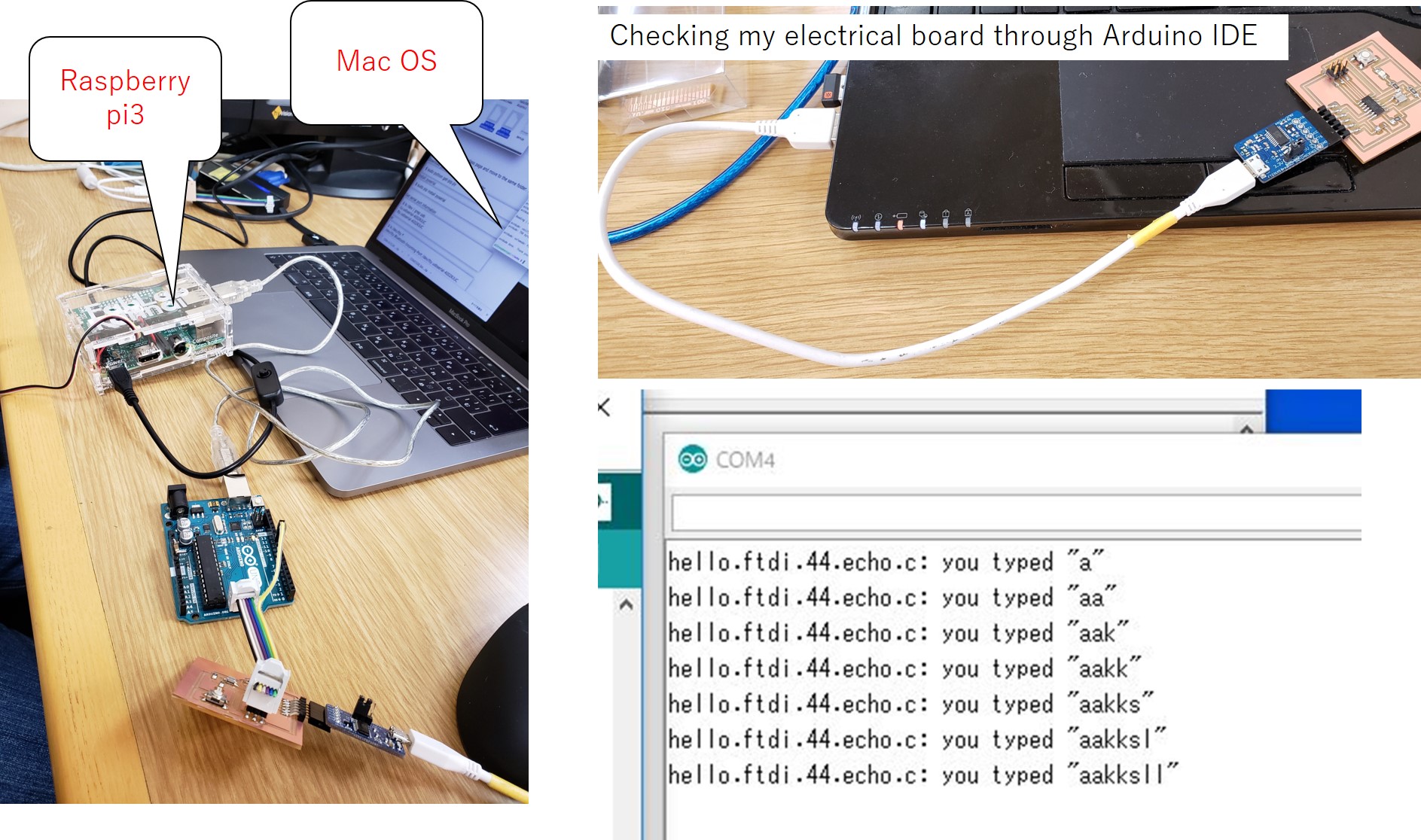
Next 3rd trial, I used my local instructor’s laptop ,Mac OS and the Arduino.
However, situation was the same…(too long time).
Then I also used raspberry pi 3 following the tutorial made by the local instructor.
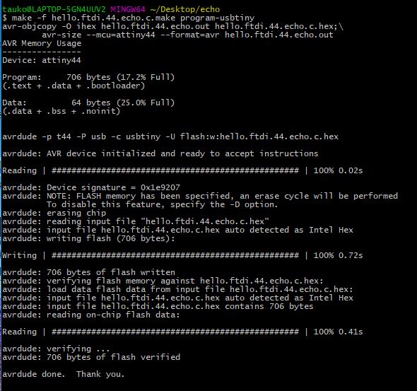
This way succeeded in completing all procedures here!
Tp check whether my electrical board was written correctly, I used Arduino IDE. The result showed wiriting a code into my electrical board was successful and this meant that there was no problem in my electrical board.
From the above all results, my FabISP and redrawn echo hello-world board do not have any problems in proper systems. Because
- My laptop could recognize my FabISP as an USB device
- The redrawn echo hello-world board could display desired response of the written code
However, as long as my FabISP could not complete all procedures here, there may be something wrong in enviroment setting in my laptop. For later class, I have to resolve this issue.
Updated progress
Thanks to great helps of our local instructor and Rico who is a student in Fablab Kamakura, I managed to succeeded in all procedures by using my FabISP.
The solution was based on this tutorial
and this.
Istalled required software
(1) AVR Toolchain
I downloaded “Atmel AVR Toolchain for Windows” from here.
In this web page, I selected “Download AVR 8-bit Toolchain v3.62 – Windows” and unzipped it by using 7zip
to inport all unzipped files in to “C:\Program Files”.
(2) GNU Make
Downloaded “Gnu Make” from GnuWin32
(3) avrdude
Downloaded avrdude
Note: From the above link, 64bit ver will be donwloaded. However, we could not find 32 bit ver software, so we had to installed WinAVR later.
After donwloading avrdude unzipped and copied to Program file.
(4) WinAVR Downloaded from here
Updated PATH and checked availability
To make the above installed softwares available, I updated my laptop’s system PATH like following.
- C:\Program Files\avr8-gnu-toolchain-win32_x86\bin
- C:\Program Files\GnuWin32\bin
- C:\Program Files\avrdude-win-64bit\avrdude
After that I checked wheter the above softwares could be used in my laptop through GitBash.
make -v
avr-gcc --version
avrdude -c usbtiny -p t45
which avr-gcc
which make
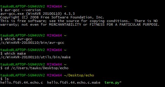
It looked like perfect.
To show the result of writing the program, I installed “pyserial” and executed the “term.py” program.
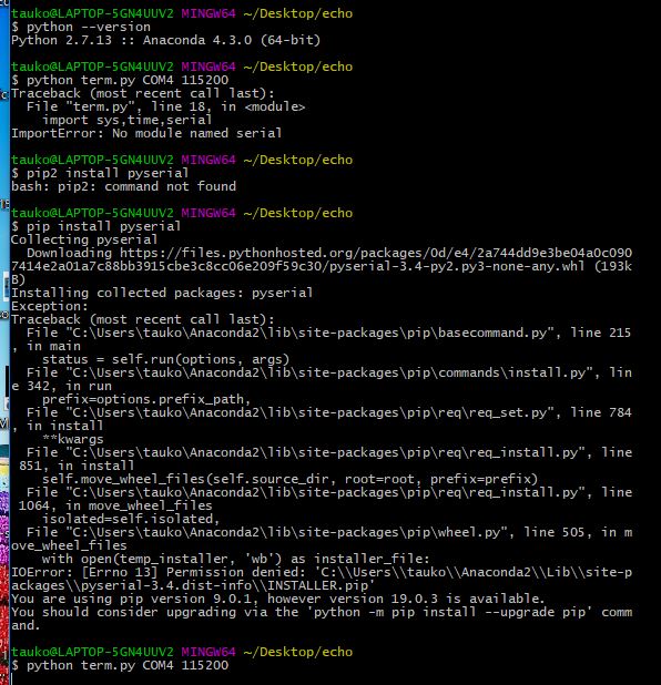
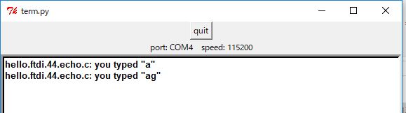
Successful!!